
wire rope lubricant specification made in china

Proper lubrication of your wire rope, chain and cable can safely extend its operational life regardless of application. Cranes, elevators, shovels, drilling rigs, suspension bridges and draglines are some of the many applications that use wire rope, chain or cable to perform work such as pulling, dragging or hoisting. These applications often are exposed to harsh environmental conditions, including extreme weather. Lubrication Engineers can help your wire rope, chain and cable last longer and operate safely by implementing a lubricant reliability program and recommending the right lubricants for the job.
Most wire ropes are lubricated during the manufacturing process, but this lubricant will not last the entire life of the rope. When looking for a lubricant to relubricate your wire rope, choose one that contains no acids or alkalis, possesses the adhesive strength to stay on the rope, can penetrate between wires and strands, has high fluid film strength, resists oxidation and remains pliable. It is important to remember that most wire ropes fail from the inside out. Corroded rope can be a safety hazard, as there is no way to determine its remaining strength and life. Proper lubrication will help prevent deterioration of wire rope due to rust and corrosion.
Because most wire ropes fail from the inside, it is critical to ensure the center core receives sufficient lubricant. LE recommends a combined regimen in which a penetrating lubricant is used to saturate the core, followed by a coating lubricant to seal and protect the outer surface. LE offers several penetrating and coating type wire rope lubricants to suit your specific needs.
Penetrating lubricants contain an evaporative solvent that facilitates migration of the lubricant into the core of the wire rope, then evaporates, leaving behind a heavy lubricating film that protects and lubricates each strand.
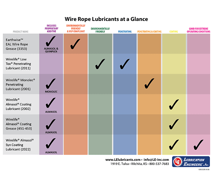
Wirelife Almasol Coating Grease (451-453) is a soft, semifluid calcium-based grease designed to coat wire rope as well as moving chain and cable parts to ensure long life and smooth, quiet operation. Its tacky, water-resistant characteristics enable it to adhere strongly to rapidly moving parts, seal out damaging moisture, protect against premature wear and shield metal against corrosive attack.
Typical Applications: Wire rope, chain links, pins, bushings, cable sheave bushings, cables, open and closed silent and roller chains, and small, slow-turning gearboxes that require a semifluid lubricant
Wirelife Almasol Coating Lubricant (2002) is a fluid wire rope lubricant that provides a tough outer coating to seal and protect against fretting corrosion, wear and rust – even under extreme load and moisture. It seals and protects better than any product available. When used in conjunction with Wirelife Monolec Penetrating Lubricant, maximum protection and wear reduction is achieved.
Wirelife Almasol Syn Coating Lubricant (2022) is an extremely tacky, nonasphaltic synthetic lubricant with exceptionally high film strength. Perfect for extreme environments and conditions, it is the ultimate outer surface protector for wire rope and cable and comes from the same advanced technology that LE developed to protect large open gears in the mining and quarry industries. It derives its high load-carrying capacity from its synergistic blend of an extreme pressure additive and Almasol, LE’s exclusive wear-reducing additive.
Wirelife Monolec Penetrating Lubricant (2001) has excellent corrosion resistance and high load-carrying (EP) properties. It penetrates to the core of wire ropes, whether they are running or stationary. It is also excellent as a penetrating lubricant for chains of all sizes and works well in a variety of other industrial applications. When used in conjunction with Wirelife Almasol Coating Lubricant, maximum protection and wear reduction is achieved.
It contains a petroleum solvent to enhance its ability to penetrate. The solvent evaporates, leaving behind a film of heavy-bodied lubricant that protects and lubricates each strand and resists leakage from the wire rope core. Available in bulk sizes or in an aerosol version.
Typical Applications: All stationary or moving wire ropes or cables under heavy loads; chains of all sizes; mining and construction applications such as standing and running lines, draglines, cranes and derricks; marine applications such as cranes, hoists and drilling rigs; any other application that requires excellent rust protection for steel parts.
Designed for marine environments and other applications where environmental concerns require the use of a very low toxicity wire rope and chain lubricant, LE’s Wirelife Low Tox Penetrating Lubricant (2011) has excellent load-carrying capability and provides outstanding protection against rust, while having the lowest possible toxic effect on the environment.
Earthwise EAL Wire Rope Grease (3353) is recommended for use in applications on or near the waterways. It is an EAL and meets the specifications required by the EPA’s Vessel General Permit (VGP). It is readily biodegradable, exhibits minimal aquatic toxicity and will not accumulate in the cells of fish and other aquatic life forms. It is a soft, semifluid formulation designed to coat wire rope as well as moving chain and cable parts to ensure long life and smooth, quiet operation. Its semi-tacky, water-resistant characteristics enable it to adhere to the application and seal out damaging moisture and protect against rust formation.
Typical Applications: Applications near or around waterways including: Wire rope; chain links, pins and bushings; cable sheave bushings, bearings and strands; open and closed silent and roller chains. Ideal for use in automatic lubrication systems.
LE is happy to offer industrial lubricant and reliability recommendations for a variety of applications, and to provide product-specific data on all of our items to help you make the right decision. To learn more about our wire rope lubricants, wire rope lubricators as well as our other enhanced lubricants and lubricant reliability products, please

Our Customers are involved in a wide array of industries that incorporate wire rope. They understand the importance of cleaning and maintaining their wire rope to keep its functional integrity and improve its longevity. The systems we produce and distribute go to urban and rural locations throughout the United States and overseas. We are proud of the results they have produced in almost every industry where wire rope longevity and safety is a priority. Wire rope is incorporated in a variety of applications, including hoisting, moving heavy parts, vehicles, and materials. You will find wire rope used in anything from cranes at shipyards, shipboard cranes, mooring lines, mine hoists, offshore anchor lines and construction sites. Since 1982, The Kirkpatrick Group, Inc. has provided industry-leading technology for wire rope pressure lubrication, first for our own company’s crane fleet, and then worldwide in hundreds of different maintenance applications. The range of maintenance applications our wire rope lubrication systems and Dynagard™ Wire Rope Lubricants are used to support is expansive.

As specialist for manufacturing quality steel wire ropes over 20 years, our company can supply strong, durable and reliable ropes that capable to minimize your downtime and maximize cost effectiveness. Decades of experience we owned make us know clearly the work you do and capable to provide professional guidance.
We select the best steel or stainless steel as raw material for wire rope manufacturing. Our products are manufactured under strict quality managements and test before they leave the factory.
Our engineers can provide professional advice about picking up optimal steel wire ropes for their application, installation guidance to ensure maximum return in their wire rope system.
If you are going to pick up steel wire ropes that suit your project perfectly, you must have an ideal about the construction about them. Our company can supply bright wire rope, galvanized wire rope, stainless steel wire rope, compacted wire rope, rotation resistant wire ropes, mining wire rope, elevator wire rope, crane wire rope and gas & oilfield wire ropes. Here are some details to solve the problem that may puzzle you whether you are browsing the web or picking up steel wire ropes.
Bright steel wire ropes mean no surface treatment is applied to the rope. Therefore, they have the lower price among these three wire ropes. Generally, they are fully lubricated to protect the rope from rust and corrosion.
Galvanized steel wire ropes feature compressed zinc coating for providing excellent corrosion resistance. With higher break strength yet lower price than stainless steel, galvanized steel wire ropes are widely used in general engineering applications such as winches and security ropes.
Stainless steel wire ropes, made of quality 304, 305, 316 steels, are the most corrosive type for marine environments and other places subjected to salt water spray. Meanwhile, bright and shiny appearance can be maintained for years rather than dull as galvanized steel wire ropes.
Steel wire ropes are composed of multiple strands of individual wires that surrounding a wire or fiber center to form a combination with excellent fatigue and abrasion resistance. These wires and strands are wound in different directions to from different lay types as follows:
Beside above lay types, alternative lay ropes which combine regular lay and lang lay together and ideal for boom hoist and winch lines, can also be supplied as your request.
Two main methods about seizing steel wire ropes in conjunction with soft or annealing wire or strands to protect cut ends of the ropes form loosening.

Ungalvanized and galvanized steel wire rope is a kind of interwoven flexible cord, which consists of strands of thin wire. It has advantages of high strength, light weight, smooth work and not easy to suddenly broken. Besides, they can serve in many circumstances. And Special specification and marks can be made according to customers requirement.
![]()
PVC steel wire rope looks more beautiful than the ordinary one, and the structure of it is more stable, which achieve the effect cushioning and anti-extrusion. So, the service life of wire rope will be prolonged. It has outstanding corrosion resistance, the service life of it is generally 3.5~5 times of galvanized steel wire rope in the atmosphere, mine and sea water.

Wire rope or cable is used for a wide variety of purposes ranging from stationary service, such as guys or stays and suspension cables, to service involving drawing or hoisting heavy loads. In these various services, all degrees of exposure to environmental conditions are encountered. These range from clean, dry conditions in applications such as elevator cables in office buildings, to full exposure to the elements on outdoor equipment. This could include immersion in water that can be encountered on dredging equipment to exposure to corrosive environments, such as acid water,
found in many mining applications. These and other operating factors require that wire ropes be properly lubricated to provide long rope life and maximum protection against rope failure where the safety of people is involved.
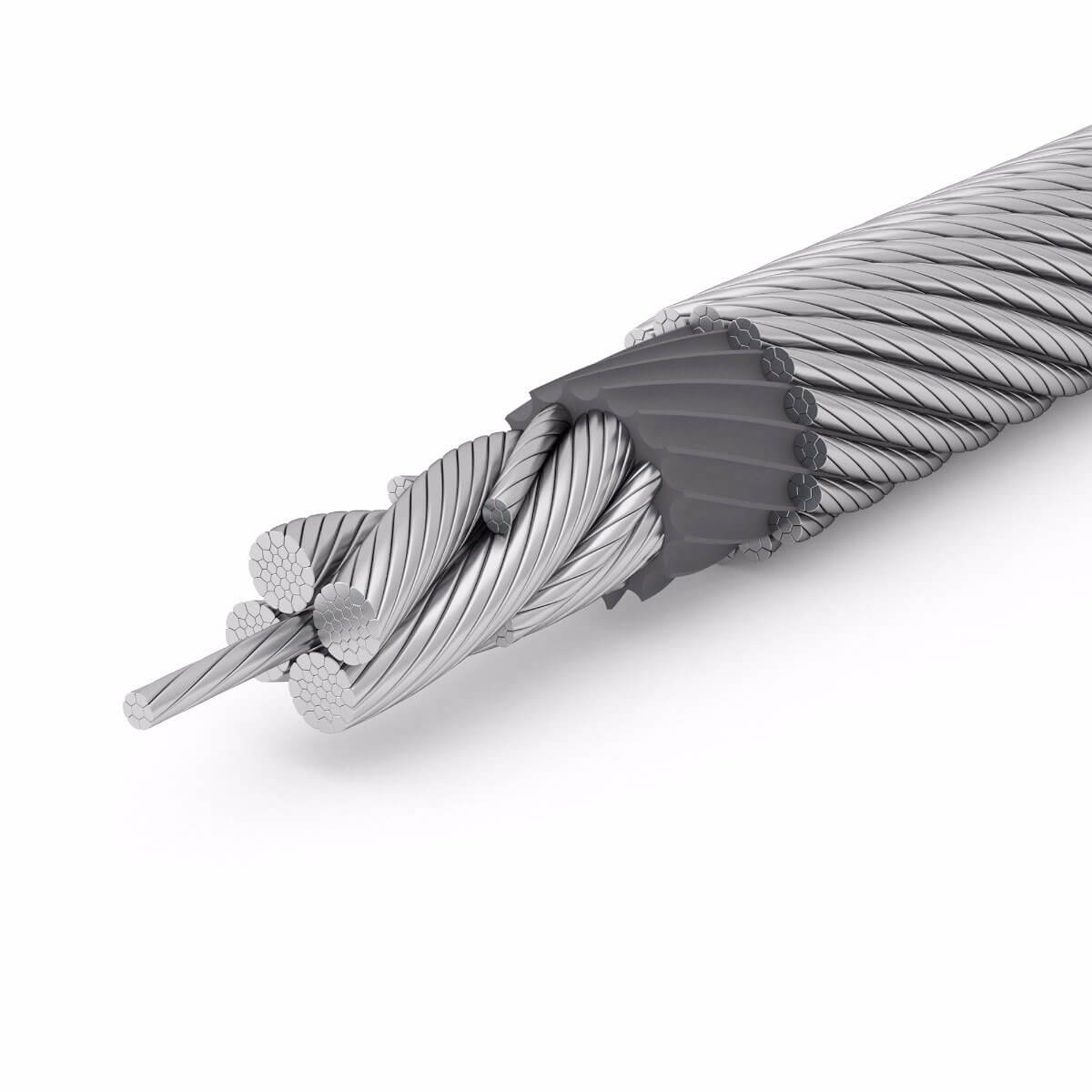
A wire rope consists of several strands laid (helically bent, not twisted) around a core. The core can be a rope made of hemp or other fiber, or may be an independent wire rope or strand. Each strand consists of several wires laid around the core, which usually consists of one or more wires but may be a small fiber rope. The number of wires per strand typically ranges from 7 to 37 or more.
Each wire of a wire rope can be in contact with three or more wires over its entire length. Each contact is theoretically along a line, but this line actually widens to a narrow band because of a deformation under load. As load is applied, and as a rope bends or flexes over rollers, sheaves, or drums, stresses are set up that cause the strands and individual wires to move with respect to each other under high contact pressures. Unless lubricating films are maintained in the contact areas, considerable friction and wear result from these movements.
One of the principal causes of wire rope failures is metal fatigue. Bending and tension stresses, repeated many times, cause fatigue. Eventually, individual wires break and the rope is progressively weakened to the extent that it must be removed from service. If lubrication is inadequate, the stresses are increased by high frictional resistance to the movement of the wires over one another, fatigue failures occur more rapidly, and rope life is shortened.
Another principal cause of rope failure is corrosion. This covers both direct attack by corrosive materials, such as acid water that may be encountered in mines, to various forms of rusting. To protect against corrosion, lubricant films that resist displacement by water must be maintained on all wire surfaces.
Wear, deterioration, or drying out of the core result in reduction of the core diameter and loss of support for the strands. The strands then tend to overlap, and severe cutting or nicking of the wires may occur. The lubricant applied in service must be of a type that will penetrate through the strands to the core to minimize friction and wear at the core surface, seal the core against water, and keep it soft and flexible.
During manufacture, wire rope cores are saturated with lubricant. A second lubricant, designed to provide a very tenacious film, is usually applied to the wires and strands to lubricate and protect the wires and to help keep (seal) the lubricant in the core as they are laid up. These lubricants protect the rope during shipment, storage, and installation.
Much of the core lubricant applied during manufacture is squeezed out when the strands are laid, and additional lubricant is lost from both the core and strands as soon as load is applied to a rope. As a result, in-service lubrication must be started almost immediately after a rope is placed in service.
Proper lubrication of wire ropes in service is not easy to accomplish. Some of the types of lubricants required for wire ropes may not be easy to apply, and often wire ropes are somewhat inaccessible. Various methods of applying lubricants are used, including brushing, spraying, pouring on a running section of the rope, drip or force feed applicators, and running the rope through a trough or bath of lubricant. Generally, the method of application is a function of the type of lubricant required to protect a rope under the conditions to which it is exposed.
These requirements necessitate some compromises. Wire rope lubricants may be formulated with asphaltic or petrolatum-based material and contain rust preventives and materials to promote metal wetting and penetration. Diluent products are used in some cases for ease of application. Grease products containing solid lubricants such as graphite or molybdenum disulfide are also used. The challenges with greases are the ability of the lubricant to penetrate to the inner core strands and its attraction for dust and dirt buildup. Wire ropes are often used in applications operating near or on an ocean, bay, river, lake, or other waterway, and as a result require environmentally acceptable wire rope lubricants to minimize their impact on the environment.
Please contact us for Your application needs and our technical support team will give You the best lubricating solution!Welcome to Lubrita.com International Lubrita Distributors network and World wide Oils & Lubricants online stores.

Rope diameter is specified by the user and is generally given in the equipment manufacturer’s instruction manual accompanying the machine on which the rope is to be used.
Rope diameters are determined by measuring the circle that just touches the extreme outer limits of the strands— that is, the greatest dimension that can be measured with a pair of parallel-jawed calipers or machinist’s caliper square. A mistake could be made by measuring the smaller dimension.
The right way to unreel.To unreel wire rope from a heavy reel, place a shaft through the center and jack up the reel far enough to clear the floor and revolve easily. One person holds the end of the rope and walks a straight line away from the reel, taking the wire rope off the top of the reel. A second person regulates the speed of the turning reel by holding a wood block against the flange as a brake, taking care to keep slack from developing on the reel, as this can easily cause a kink in the rope. Lightweight reels can be properly unreeled using a vertical shaft; the same care should be taken to keep the rope taut.
The wrong way to unreel.If a reel of wire rope is laid on its flange with its axis vertical to the floor and the rope unreeled by throwing off the turns, spirals will occur and kinks are likely to form in the rope. Wire rope always should be handled in a way that neither twists nor unlays it. If handled in a careless manner, reverse bends and kinks can easily occur.
The right way to uncoil.There is only one correct way to uncoil wire rope. One person must hold the end of the rope while a second person rolls the coil along the floor, backing away. The rope is allowed to uncoil naturally with the lay, without spiraling or twisting. Always uncoil wire rope as shown.
The wrong way to uncoil.If a coil of wire rope is laid flat on the floor and uncoiled by pulling it straight off, spirals will occur and kinking is likely. Torsions are put into the rope by every loop that is pulled off, and the rope becomes twisted and unmanageable. Also, wire rope cannot be uncoiled like hemp rope. Pulling one end through the middle of the coil will only result in kinking.
Great stress has been placed on the care that should be taken to avoid kinks in wire rope. Kinks are places where the rope has been unintentionally bent to a permanent set. This happens where loops are pulled through by tension on the rope until the diameter of the loop is only a few inches. They also are caused by bending a rope around a sheave having too severe a radius. Wires in the strands at the kink are permanently damagedand will not give normal service, even after apparent “re-straightening.”
When wire rope is wound onto a sheave or drum, it should bend in the manner in which it was originally wound. This will avoid causing a reverse bend in the rope. Always wind wire rope from the top of the one reel onto the top of the other.Also acceptable, but less so, is re-reeling from the bottom of one reel to the bottom of another. Re-reeling also may be done with reels having their shafts vertical, but extreme care must be taken to ensure that the rope always remains taut. It should never be allowed to drop below the lower flange of the reel. A reel resting on the floor with its axis horizontal may also be rolled along the floor to unreel the rope.
Wire rope should be attached at the correct location on a flat or smooth-faced drum, so that the rope will spool evenly, with the turns lying snugly against each other in even layers. If wire rope is wound on a smooth-face drum in the wrong direction, the turns in the first layer of rope will tend to spread apart on the drum. This results in the second layer of rope wedging between the open coils, crushing and flattening the rope as successive layers are spooled.
A simple method of determining how a wire rope should be started on a drum. The observer stands behind the drum, with the rope coming towards him. Using the right hand for right-lay wire rope, and the left hand for left lay wire rope, the clenched fist denotes the drum, the extended index finger the oncoming rope.
Clips are usually spaced about six wire rope diameters apart to give adequate holding power. They should be tightened before the rope is placed under tension. After the load is placed on the rope, tighten the clips again to take care of any lessening in rope diameter caused by tension of the load. A wire rope thimble should be used in the eye of the loop to prevent kinking.
U-bolt Clips.There is only one correct method for attaching U-bolt clips to wire rope ends, as shown in TheRightWayimage below. The base of the clip bears on the live end of the rope; the “U” of the bolt bears on the dead end.
Compare this with the incorrect methods. Five of the six clips shown are incorrectly attached—only the center clip in the top view is correct. When the “U” of the clip bears on the live end of the rope, there is a possibility of the rope being cut or kinked, with subsequent failure.
Proper seizing and cutting operations are not difficult to perform, and they ensure that the wire rope will meet the user’s performance expectations. Proper seizings must be applied on both sides of the place where the cut is to be made. In a wire rope, carelessly or inadequately seized ends may become distorted and flattened, and the strands may loosen. Subsequently, when the rope is operated, there may be an uneven distribution of loads to the strands; a condition that will significantly shorten the life of the rope.
Either of the following seizing methods is acceptable. Method No. 1 is usually used on wire ropes over one inch in diameter. Method No. 2 applies to ropes one inch and under.
Method No. 1: Place one end of the seizing wire in the valley between two strands. Then turn its long end at right angles to the rope and closely and tightly wind the wire back over itself and the rope until the proper length of seizing has been applied. Twist the two ends of the wire together, and by alternately pulling and twisting, draw the seizing tight.
The Seizing Wire. The seizing wire should be soft or annealed wire or strand. Seizing wire diameter and the length of the seize will depend on the diameter of the wire rope. The length of the seizing should never be less than the diameter of the rope being seized.
Proper end seizing while cutting and installing, particularly on rotation-resistant ropes, is critical. Failure to adhere to simple precautionary measures may cause core slippage and loose strands, resulting in serious rope damage. Refer to the table below ("Suggested Seizing Wire Diameters") for established guidelines. If core protrusion occurs beyond the outer strands, or core retraction within the outer strands, cut the rope flush to allow for proper seizing of both the core and outer strands.
The majority of wire rope problems occurring during operation actually begin during installation, when the rope is at its greatest risk of being damaged. Proper installation procedures are vital in the protection and performance of wire rope products.
Until the rope is installed it should be stored on a rack, pallet or reel stand in a dry, well-ventilated storage shed or building. Tightly sealed and unheated structures should be avoided as condensation between rope strands may occur and cause corrosion problems. If site conditions demand outside storage, cover the rope with waterproof material and place the reel or coil on a support platform to keep it from coming directly in contact with the ground.
While lubrication is applied during the manufacturing process, the wire rope must still be protected by additional lubrication once it is installed. Lubricants will dry out over a period of time and corrosion from the elements will occur unless measures are taken to prevent this from happening. When the machine becomes idle for a period of time, apply a protective coating of lubricant to the wire rope. Moisture (dew, rain, and snow) trapped between strands and wires will create corrosion if the rope is unprotected. Also apply lubricant to each layer of wire rope on a drum because moisture trapped between layers will increase the likelihood of corrosion.
Always use the nominal diameter as specified by the equipment manufacturer. Using a smaller diameter rope will cause increased stresses on the rope and the probability of a critical failure is increased if the rated breaking strength does not match that of the specified diameter. Using a larger diameter rope leads to shorter service life as the rope is pinched in the sheave and drum grooves which were originally designed for a smaller diameter rope. Just as using a different diameter rope can create performance problems, so can the use of an excessively undersized or oversized rope.
Measure the wire rope using a parallel-jawed caliper as discussed in Measuring Rope Diameter at the top of this page. If the rope is the wrong size or outside the recommended tolerance, return the rope to the wire rope supplier. It is never recommended nor permitted by federal standards to operate cranes with the incorrect rope diameter. Doing so will affect the safety factor or reduce service life and damage the sheaves and drum. Note that in a grooved drum application, the pitch of the groove may be designed for the rope’s nominal diameter and not the actual diameter as permitted by federal standards.
Wire rope can be permanently damaged by improper unreeling or uncoiling practices. The majority of wire rope performance problems start here.Improper unreeling practices lead to premature rope replacement, hoisting problems and rope failure.
Place the payout reel as far away from the boom tip as is practical, moving away from the crane chassis. Never place the payout reel closer to the crane chassis than the boom point sheave. Doing so may introduce a reverse bend into the rope and cause spooling problems. Follow the guidelines highlighted under Unreeling and Uncoiling and Drum Winding. Take care to determine whether the wire rope will wind over or under the drum before proceeding. If the wire rope supplier secured the end of the rope to the reel by driving a nail through the strands, ask that in the future a U-bolt or other nondestructive tie-down method be used; nails used in this manner damage the rope.
Take extra precaution when installing lang lay, rotation-resistant, flattened strand or compacted ropes. Loss of twist must be avoided to prevent the strands from becoming loosened, causing looped wire problems.
The end of the rope must be securely and evenly attached to the drum anchorage point by the method recommended by the equipment manufacturer. Depending on the crane’s regulatory requirements, at least two to three wraps must remain on the drum as dead wraps when the rope is unwound during normal operations. Locate the dead end rope anchorage point on the drum in relation to the direction of the lay of the rope. Do not use an anchorage point that does not correspond with the rope lay. Mismatching rope lay and anchorage point will cause the wraps to spread apart from each other and allow the rope to cross over on the drum. Very gappy winding will occur resulting in crushing damage in multilayer applications.
Back tension must be continually applied to the payout reel and the crewman installing the rope must proceed at a slow and steady pace whether the drum is smooth or grooved.Regardless of the benefits of a grooved drum, tension must be applied to ensure proper spooling. An improperly installed rope on a grooved drum will wear just as quickly as an improperly installed rope on a smooth drum. If a wire rope is poorly wound and as a result jumps the grooves, it will be crushed and cut under operating load conditions where it crosses the grooves.
Every wrap on the first or foundation layer must be installed very tightly and be without gaps. Careless winding results in poor spooling and will eventually lead to short service life. The following layers of rope must lay in the grooves formed between adjacent turns of the preceding layer of rope. If any type of overwind or cross-winding occurs at this stage of installation and is not corrected immediately, poor spooling and crushing damage will occur.
On a multilayer spooling drum be sure that the last layer remains at least two rope diameters below the drum flange top. Do not use a longer length than is required because the excess wire rope will cause unnecessary crushing and may jump the flange. Loose wraps that occur at any time must be corrected immediately to prevent catastrophic rope failure.
The use of a mallet is acceptable to ensure tight wraps, however a steel-faced mallet should be covered with plastic or rubber to prevent damage to the rope wires and strands.
Rotation-resistant ropes of all constructions require extra care in handling to prevent rope damage during installation. The lay length of a rotation-resistant rope must not be disturbed during the various stages of installation. By introducing twist or torque into the rope, core slippage may occur—the outer strands become shorter in length, the core slips and protrudes from the rope. In this condition the outer strands become over- loaded because the core is no longer taking its designed share of the load. Conversely, when torque is removed from a rotation-resistant rope core slippage can also occur. The outer strands become longer and the inner layers or core become overloaded, reducing service life and causing rope failure.
The plain end of a wire rope must be properly secured. If the entire cross section of the rope is not firmly secured, core slippage may occur, causing the core to pull inside the rope’s end and allowing it to protrude elsewhere, either through the outer strands (popped core) or out the other end of the line. The outer layer of the outside strands may also become overloaded as there is no complete core-to-strand support.
Secure the ends of the rope with either seizing or welding methods as recommended under Seizing Wire Rope. It is imperative that the ends be held together tightly and uniformly throughout the entire installation procedure, including attaching the end through the wedge socket and the drum dead end wedge
When installing a new line, connect the old line to the new line by using a swivel-equipped cable snake or Chinese finger securely attached to the rope ends. The connection between the ropes during change-out must be very strong and prevent torque from the old rope being transferred into the new rope.Welding ropes together or using a cable snake without the benefit of a swivel increases the likelihood of introducing torque into the new rope. A swivel-equipped cable snake is not as easy as welding the ropes, but this procedure can be mastered with a little patience and practice.
Bridon-Bekaert Ropes Group concludes investment and commercial partnership with TFI Marine, Dublin, Ireland, to accelerate the go-to-market of digital-enabled mooring solutions

In stricter senses, the term wire rope refers to a diameter larger than 9.5 mm (3⁄8 in), with smaller gauges designated cable or cords.wrought iron wires were used, but today steel is the main material used for wire ropes.
Historically, wire rope evolved from wrought iron chains, which had a record of mechanical failure. While flaws in chain links or solid steel bars can lead to catastrophic failure, flaws in the wires making up a steel cable are less critical as the other wires easily take up the load. While friction between the individual wires and strands causes wear over the life of the rope, it also helps to compensate for minor failures in the short run.
Wire ropes were developed starting with mining hoist applications in the 1830s. Wire ropes are used dynamically for lifting and hoisting in cranes and elevators, and for transmission of mechanical power. Wire rope is also used to transmit force in mechanisms, such as a Bowden cable or the control surfaces of an airplane connected to levers and pedals in the cockpit. Only aircraft cables have WSC (wire strand core). Also, aircraft cables are available in smaller diameters than wire rope. For example, aircraft cables are available in 1.2 mm (3⁄64 in) diameter while most wire ropes begin at a 6.4 mm (1⁄4 in) diameter.suspension bridges or as guy wires to support towers. An aerial tramway relies on wire rope to support and move cargo overhead.
Modern wire rope was invented by the German mining engineer Wilhelm Albert in the years between 1831 and 1834 for use in mining in the Harz Mountains in Clausthal, Lower Saxony, Germany.chains, such as had been used before.
Wilhelm Albert"s first ropes consisted of three strands consisting of four wires each. In 1840, Scotsman Robert Stirling Newall improved the process further.John A. Roebling, starting in 1841suspension bridge building. Roebling introduced a number of innovations in the design, materials and manufacture of wire rope. Ever with an ear to technology developments in mining and railroading, Josiah White and Erskine Hazard, principal ownersLehigh Coal & Navigation Company (LC&N Co.) — as they had with the first blast furnaces in the Lehigh Valley — built a Wire Rope factory in Mauch Chunk,Pennsylvania in 1848, which provided lift cables for the Ashley Planes project, then the back track planes of the Summit Hill & Mauch Chunk Railroad, improving its attractiveness as a premier tourism destination, and vastly improving the throughput of the coal capacity since return of cars dropped from nearly four hours to less than 20 minutes. The decades were witness to a burgeoning increase in deep shaft mining in both Europe and North America as surface mineral deposits were exhausted and miners had to chase layers along inclined layers. The era was early in railroad development and steam engines lacked sufficient tractive effort to climb steep slopes, so incline plane railways were common. This pushed development of cable hoists rapidly in the United States as surface deposits in the Anthracite Coal Region north and south dove deeper every year, and even the rich deposits in the Panther Creek Valley required LC&N Co. to drive their first shafts into lower slopes beginning Lansford and its Schuylkill County twin-town Coaldale.
The German engineering firm of Adolf Bleichert & Co. was founded in 1874 and began to build bicable aerial tramways for mining in the Ruhr Valley. With important patents, and dozens of working systems in Europe, Bleichert dominated the global industry, later licensing its designs and manufacturing techniques to Trenton Iron Works, New Jersey, USA which built systems across America. Adolf Bleichert & Co. went on to build hundreds of aerial tramways around the world: from Alaska to Argentina, Australia and Spitsbergen. The Bleichert company also built hundreds of aerial tramways for both the Imperial German Army and the Wehrmacht.
In the last half of the 19th century, wire rope systems were used as a means of transmitting mechanical powercable cars. Wire rope systems cost one-tenth as much and had lower friction losses than line shafts. Because of these advantages, wire rope systems were used to transmit power for a distance of a few miles or kilometers.
Steel wires for wire ropes are normally made of non-alloy carbon steel with a carbon content of 0.4 to 0.95%. The very high strength of the rope wires enables wire ropes to support large tensile forces and to run over sheaves with relatively small diameters.
In the mostly used parallel lay strands, the lay length of all the wire layers is equal and the wires of any two superimposed layers are parallel, resulting in linear contact. The wire of the outer layer is supported by two wires of the inner layer. These wires are neighbors along the whole length of the strand. Parallel lay strands are made in one operation. The endurance of wire ropes with this kind of strand is always much greater than of those (seldom used) with cross lay strands. Parallel lay strands with two wire layers have the construction Filler, Seale or Warrington.
In principle, spiral ropes are round strands as they have an assembly of layers of wires laid helically over a centre with at least one layer of wires being laid in the opposite direction to that of the outer layer. Spiral ropes can be dimensioned in such a way that they are non-rotating which means that under tension the rope torque is nearly zero. The open spiral rope consists only of round wires. The half-locked coil rope and the full-locked coil rope always have a centre made of round wires. The locked coil ropes have one or more outer layers of profile wires. They have the advantage that their construction prevents the penetration of dirt and water to a greater extent and it also protects them from loss of lubricant. In addition, they have one further very important advantage as the ends of a broken outer wire cannot leave the rope if it has the proper dimensions.
Stranded ropes are an assembly of several strands laid helically in one or more layers around a core. This core can be one of three types. The first is a fiber core, made up of synthetic material or natural fibers like sisal. Synthetic fibers are stronger and more uniform but cannot absorb much lubricant. Natural fibers can absorb up to 15% of their weight in lubricant and so protect the inner wires much better from corrosion than synthetic fibers do. Fiber cores are the most flexible and elastic, but have the downside of getting crushed easily. The second type, wire strand core, is made up of one additional strand of wire, and is typically used for suspension. The third type is independent wire rope core (IWRC), which is the most durable in all types of environments.ordinary lay rope if the lay direction of the wires in the outer strands is in the opposite direction to the lay of the outer strands themselves. If both the wires in the outer strands and the outer strands themselves have the same lay direction, the rope is called a lang lay rope (from Dutch langslag contrary to kruisslag,Regular lay means the individual wires were wrapped around the centers in one direction and the strands were wrapped around the core in the opposite direction.
Multi-strand ropes are all more or less resistant to rotation and have at least two layers of strands laid helically around a centre. The direction of the outer strands is opposite to that of the underlying strand layers. Ropes with three strand layers can be nearly non-rotating. Ropes with two strand layers are mostly only low-rotating.
Stationary ropes, stay ropes (spiral ropes, mostly full-locked) have to carry tensile forces and are therefore mainly loaded by static and fluctuating tensile stresses. Ropes used for suspension are often called cables.
Track ropes (full locked ropes) have to act as rails for the rollers of cabins or other loads in aerial ropeways and cable cranes. In contrast to running ropes, track ropes do not take on the curvature of the rollers. Under the roller force, a so-called free bending radius of the rope occurs. This radius increases (and the bending stresses decrease) with the tensile force and decreases with the roller force.
Wire rope slings (stranded ropes) are used to harness various kinds of goods. These slings are stressed by the tensile forces but first of all by bending stresses when bent over the more or less sharp edges of the goods.
Technical regulations apply to the design of rope drives for cranes, elevators, rope ways and mining installations. Factors that are considered in design include:
Donandt force (yielding tensile force for a given bending diameter ratio D/d) - strict limit. The nominal rope tensile force S must be smaller than the Donandt force SD1.
The wire ropes are stressed by fluctuating forces, by wear, by corrosion and in seldom cases by extreme forces. The rope life is finite and the safety is only ensured by inspection for the detection of wire breaks on a reference rope length, of cross-section loss, as well as other failures so that the wire rope can be replaced before a dangerous situation occurs. Installations should be designed to facilitate the inspection of the wire ropes.
Lifting installations for passenger transportation require that a combination of several methods should be used to prevent a car from plunging downwards. Elevators must have redundant bearing ropes and a safety gear. Ropeways and mine hoistings must be permanently supervised by a responsible manager and the rope must be inspected by a magnetic method capable of detecting inner wire breaks.
The end of a wire rope tends to fray readily, and cannot be easily connected to plant and equipment. There are different ways of securing the ends of wire ropes to prevent fraying. The common and useful type of end fitting for a wire rope is to turn the end back to form a loop. The loose end is then fixed back on the wire rope. Termination efficiencies vary from about 70% for a Flemish eye alone; to nearly 90% for a Flemish eye and splice; to 100% for potted ends and swagings.
When the wire rope is terminated with a loop, there is a risk that it will bend too tightly, especially when the loop is connected to a device that concentrates the load on a relatively small area. A thimble can be installed inside the loop to preserve the natural shape of the loop, and protect the cable from pinching and abrading on the inside of the loop. The use of thimbles in loops is industry best practice. The thimble prevents the load from coming into direct contact with the wires.
A wire rope clip, sometimes called a clamp, is used to fix the loose end of the loop back to the wire rope. It usually consists of a U-bolt, a forged saddle, and two nuts. The two layers of wire rope are placed in the U-bolt. The saddle is then fitted to the bolt over the ropes (the saddle includes two holes to fit to the U-bolt). The nuts secure the arrangement in place. Two or more clips are usually used to terminate a wire rope depending on the diameter. As many as eight may be needed for a 2 in (50.8 mm) diameter rope.
The mnemonic "never saddle a dead horse" means that when installing clips, the saddle portion of the assembly is placed on the load-bearing or "live" side, not on the non-load-bearing or "dead" side of the cable. This is to protect the live or stress-bearing end of the rope against crushing and abuse. The flat bearing seat and extended prongs of the body are designed to protect the rope and are always placed against the live end.
An eye splice may be used to terminate the loose end of a wire rope when forming a loop. The strands of the end of a wire rope are unwound a certain distance, then bent around so that the end of the unwrapped length forms an eye. The unwrapped strands are then plaited back into the wire rope, forming the loop, or an eye, called an eye splice.
A Flemish eye, or Dutch Splice, involves unwrapping three strands (the strands need to be next to each other, not alternates) of the wire and keeping them off to one side. The remaining strands are bent around, until the end of the wire meets the "V" where the unwrapping finished, to form the eye. The strands kept to one side are now re-wrapped by wrapping from the end of the wire back to the "V" of the eye. These strands are effectively rewrapped along the wire in the opposite direction to their original lay. When this type of rope splice is used specifically on wire rope, it is called a "Molly Hogan", and, by some, a "Dutch" eye instead of a "Flemish" eye.
Swaging is a method of wire rope termination that refers to the installation technique. The purpose of swaging wire rope fittings is to connect two wire rope ends together, or to otherwise terminate one end of wire rope to something else. A mechanical or hydraulic swager is used to compress and deform the fitting, creating a permanent connection. Threaded studs, ferrules, sockets, and sleeves are examples of different swaged terminations.
A wedge socket termination is useful when the fitting needs to be replaced frequently. For example, if the end of a wire rope is in a high-wear region, the rope may be periodically trimmed, requiring the termination hardware to be removed and reapplied. An example of this is on the ends of the drag ropes on a dragline. The end loop of the wire rope enters a tapered opening in the socket, wrapped around a separate component called the wedge. The arrangement is knocked in place, and load gradually eased onto the rope. As the load increases on the wire rope, the wedge become more secure, gripping the rope tighter.
Poured sockets are used to make a high strength, permanent termination; they are created by inserting the wire rope into the narrow end of a conical cavity which is oriented in-line with the intended direction of strain. The individual wires are splayed out inside the cone or "capel", and the cone is then filled with molten lead-antimony-tin (Pb80Sb15Sn5) solder or "white metal capping",zincpolyester resin compound.
Donald Sayenga. "Modern History of Wire Rope". History of the Atlantic Cable & Submarine Telegraphy (atlantic-cable.com). Archived from the original on 3 February 2014. Retrieved 9 April 2014.

Scope. This section applies to slings used in conjunction with other material handling equipment for the movement of material by hoisting, in employments covered by this part. The types of slings covered are those made from alloy steel chain, wire rope, metal mesh, natural or synthetic fiber rope (conventional three strand construction), and synthetic web (nylon, polyester, and polypropylene).
Cable laid endless sling-mechanical joint is a wire rope sling made endless by joining the ends of a single length of cable laid rope with one or more metallic fittings.
Cable laid grommet-hand tucked is an endless wire rope sling made from one length of rope wrapped six times around a core formed by hand tucking the ends of the rope inside the six wraps.
Cable laid rope sling-mechanical joint is a wire rope sling made from a cable laid rope with eyes fabricated by pressing or swaging one or more metal sleeves over the rope junction.
Master link or gathering ring is a forged or welded steel link used to support all members (legs) of an alloy steel chain sling or wire rope sling. (See Fig. N-184-3.)
Diagram indicates Forms of Hitch and Kind of Sling. Eye&Eye Vertical Hitch. Eye&Eye Choker Hitch. Eye&Eye Basket Hitch (Alterates have identical load rations). Endless Vertical Hitch. Endless Choker Hitch. Endless Basket Hitch (Alternateve have identical load ratings). Notes: Angles 5 deg or less from the veritcal may be considered vertical angles. For slings with legs more than 5 deg off vertical, the actual angle as shown in Figure N-184-5 must be considered. Explanation of Symbols: Minimum Diameter of Curvature. Represents a contact surface which shall have a diameter of curvature at least double the diameter of the rope from which the sling is made. Represents a contact surface which shall have a diameter of curvature at least 8 times the diameter of the rope. Represents a load in a choker hitch and illustrates the rotary force on the load and/or the slippage of the rope in contact with the load. Diameter of curvature of load surface shall be at least double the diameter of the rope.
Strand laid endless sling-mechanical joint is a wire rope sling made endless from one length of rope with the ends joined by one or more metallic fittings.
Strand laid grommet-hand tucked is an endless wire rope sling made from one length of strand wrapped six times around a core formed by hand tucking the ends of the strand inside the six wraps.
Strand laid rope is a wire rope made with strands (usually six or eight) wrapped around a fiber core, wire strand core, or independent wire rope core (IWRC).
Proof testing. The employer shall ensure that before use, each new, repaired, or reconditioned alloy steel chain sling, including all welded components in the sling assembly, shall be proof tested by the sling manufacturer or equivalent entity, in accordance with paragraph 5.2 of the American Society of Testing and Materials Specification A391-65, which is incorporated by reference as specified in § 1910.6 (ANSI G61.1-1968). The employer shall retain a certificate of the proof test and shall make it available for examination.
Sling use. Employers must use only wire-rope slings that have permanently affixed and legible identification markings as prescribed by the manufacturer, and that indicate the recommended safe working load for the type(s) of hitch(es) used, the angle upon which it is based, and the number of legs if more than one.
Cable laid and 6 × 19 and 6 × 37 slings shall have a minimum clear length of wire rope 10 times the component rope diameter between splices, sleeves or end fittings.
Safe operating temperatures. Fiber core wire rope slings of all grades shall be permanently removed from service if they are exposed to temperatures in excess of 200 °F. When nonfiber core wire rope slings of any grade are used at temperatures above 400 °F or below minus 60 °F, recommendations of the sling manufacturer regarding use at that temperature shall be followed.
Sling use. Employers must use natural and synthetic fiber-rope slings that have permanently affixed and legible identification markings stating the rated capacity for the type(s) of hitch(es) used and the angle upon which it is based, type of fiber material, and the number of legs if more than one.
Safe operating temperatures. Natural and synthetic fiber rope slings, except for wet frozen slings, may be used in a temperature range from minus 20 °F to plus 180 °F without decreasing the working load limit. For operations outside this temperature range and for wet frozen slings, the sling manufacturer"s recommendations shall be followed.
Splicing. Spliced fiber rope slings shall not be used unless they have been spliced in accordance with the following minimum requirements and in accordance with any additional recommendations of the manufacturer:
In manila rope, eye splices shall consist of at least three full tucks, and short splices shall consist of at least six full tucks, three on each side of the splice center line.
In synthetic fiber rope, eye splices shall consist of at least four full tucks, and short splices shall consist of at least eight full tucks, four on each side of the center line.
Strand end tails shall not be trimmed flush with the surface of the rope immediately adjacent to the full tucks. This applies to all types of fiber rope and both eye and short splices. For fiber rope under one inch in diameter, the tail shall project at least six rope diameters beyond the last full tuck. For fiber rope one inch in diameter and larger, the tail shall project at least six inches beyond the last full tuck. Where a projecting tail interferes with the use of the sling, the tail shall be tapered and spliced into the body of the rope using at least two additional tucks (which will require a tail length of approximately six rope diameters beyond the last full tuck).
Removal from service. Natural and synthetic fiber rope slings shall be immediately removed from service if any of the following conditions are present:
Wire rope is made of plaiting strands of wire – normally medium carbon steel –into a thick cable. The strands are formed around a core. The strands in wire ropes are made of wore twisted together. Strands with smaller diameter wires are less abrasion resistant and more fatigue resistant. Strands made with thicker length of wore are more abrasion resistant and less fatigue resistant.
Left-hand ordinary lay (LHOL) wire rope (close-up). Right-hand lay strands are laid into a left-hand lay rope. Right-hand Lang"s lay (RHLL) wire rope (close-up). Right-hand lay strands are laid into a right-hand lay rope.
Left hand lay or right hand lay describe the manner in which the strands are laid to form the rope. To determine the lay of strands in the rope, a viewer looks at the rope as it points away from them. If the strands appear to turn in a clockwise direction, or like a right-hand thread, as the strands progress away from the viewer, the rope has a right hand lay. The picture of steel wire rope on this page shows a rope with right hand lay. If the strands appear to turn in an anti-clockwise direction, or like a left-hand thread, as the strands progress away from the viewer, the rope has a left hand lay.
Ordinary and Lang"s lay describe the manner in which the wires are laid to form a strand of the wire rope. To determine which has been used first identify if left or right hand lay has been used to make the rope. Then identify if a right or left hand lay has been used to twist the wires in each strand. Ordinary lay The lay of wires in each strand is in the opposite direction to the lay of the strands that form the wire.
Alternate lay The lay of wires in the strands alternate around the rope between being in the opposite and same direction to the lay of the strands that form the wire rope.
The specification of a wire rope type – including the number of wires per strand, the number of strands, and the lay of the rope – is documented using a commonly accepted coding system, consisting of a number of abbreviations.
This is easily demonstrated with a simple example. The rope shown in the figure "Wire rope construction" is designated thus: 6x19 FC RH OL FSWR 6 Number of strands that make up the rope
Each of the sections of the wire rope designation described above is variable. There are therefore a large number of combinations of wire rope that can be specified in this manner. The following abbreviations are commonly used to specify a wire rope. Abbr. Description
The end of a wire rope tends to fray readily, and cannot be easily connected to plant and equipment. A number of different mechanisms exist to secure the ends of wire ropes to make them more useful. The most common and useful type of end fitting for a wire rope is when the end is turned back to form a loop. The loose end is then fixed by any number of methods back to the wire rope.
When the wire rope is terminated with a loop, there is a risk that the wire rope can bend too tightly, especially when the loop is connected to a device that spreads the load over a relatively small area. A thimble can be installed inside the loop to preserve the natural shape of the loop, and protect the cable from pinching and abrasion on the inside of the loop. The use of thimbles in loops is industry best practice. The thimble prevents the load from coming into direct contact with the wires.
A wire rope clamp, also called a clip, is used to fix the loose end of the loop back to the wire rope. It usually consists of a u-shaped bolt, a forged saddle and two nuts. The two layers of wire rope are placed in the u-bolt. The saddle is then fitted over the ropes on to the bolt (the saddle includes two holes to fit to the u-bolt). The nuts secure the arrangement in place. Three or more clamps are usually used to terminate a wire rope.
Swaging is a method of wire rope termination that refers to the installation technique. The purpose of swaging wire rope fittings is to connect two wire rope ends together, or to otherwise terminate one end of wire rope to something else. A mechanical or hydraulic swager is used to compress and deform the fitting, creating a permanent connection. There are many types of swaged fittings. Threaded Studs, Ferrules, Sockets, and Sleeves a few examples.
A socket termination is useful when the fitting needs to be replaced frequently. For example, if the end of a wire rope is in a high-wear region, the rope may be periodically trimmed, requiring the termination hardware to be removed and reapplied. An example of this is on the ends of the drag ropes on a dragline. The end loop of the wire rope enters a tapered opening in the socket, wrapped around a separate component called the wedge. The arrangement is knocked in place, and load gradually eased onto the rope. As the load increases on the wire rope, the wedge become more secure, gripping the rope tighter.


 8613371530291