
mud pump suction line free sample

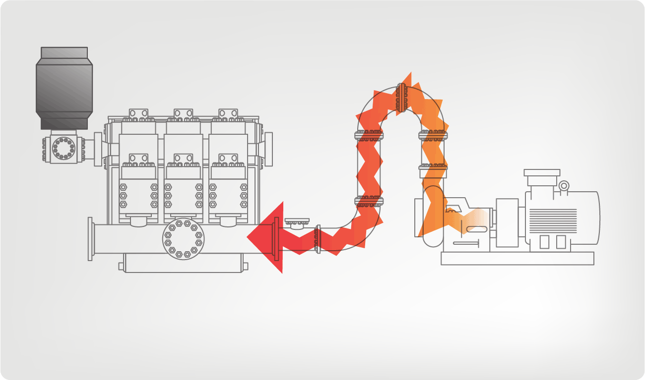
I’ve run into several instances of insufficient suction stabilization on rigs where a “standpipe” is installed off the suction manifold. The thought behind this design was to create a gas-over-fluid column for the reciprocating pump and eliminate cavitation.
When the standpipe is installed on the suction manifold’s deadhead side, there’s little opportunity to get fluid into all the cylinders to prevent cavitation. Also, the reciprocating pump and charge pump are not isolated.
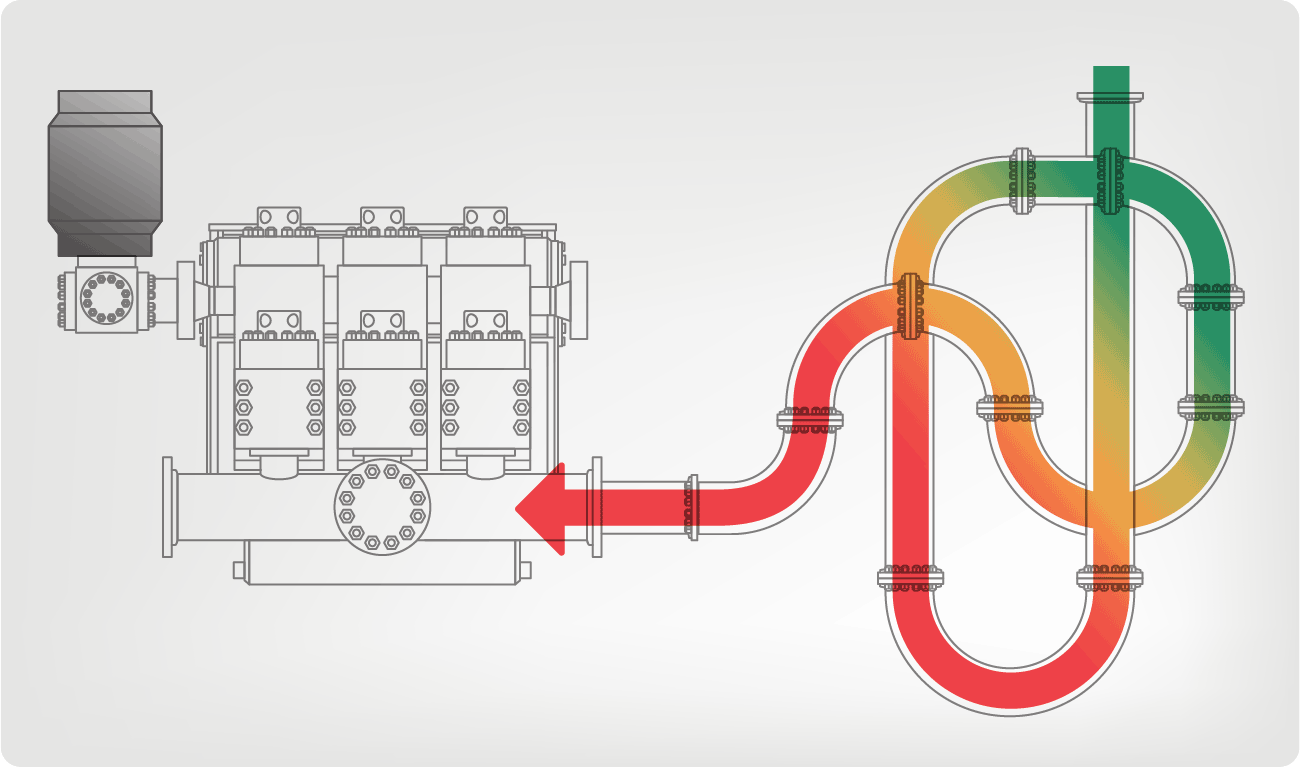
Installing a suction stabilizer from the suction manifold port supports the manifold’s capacity to pull adequate fluid and eliminates the chance of manifold fluid deficiency, which ultimately prevents cavitation.
Another benefit of installing a suction stabilizer is eliminating the negative energies in fluids caused by the water hammer effect from valves quickly closing and opening.
The suction stabilizer’s compressible feature is designed to absorb the negative energies and promote smooth fluid flow. As a result, pump isolation is achieved between the charge pump and the reciprocating pump.
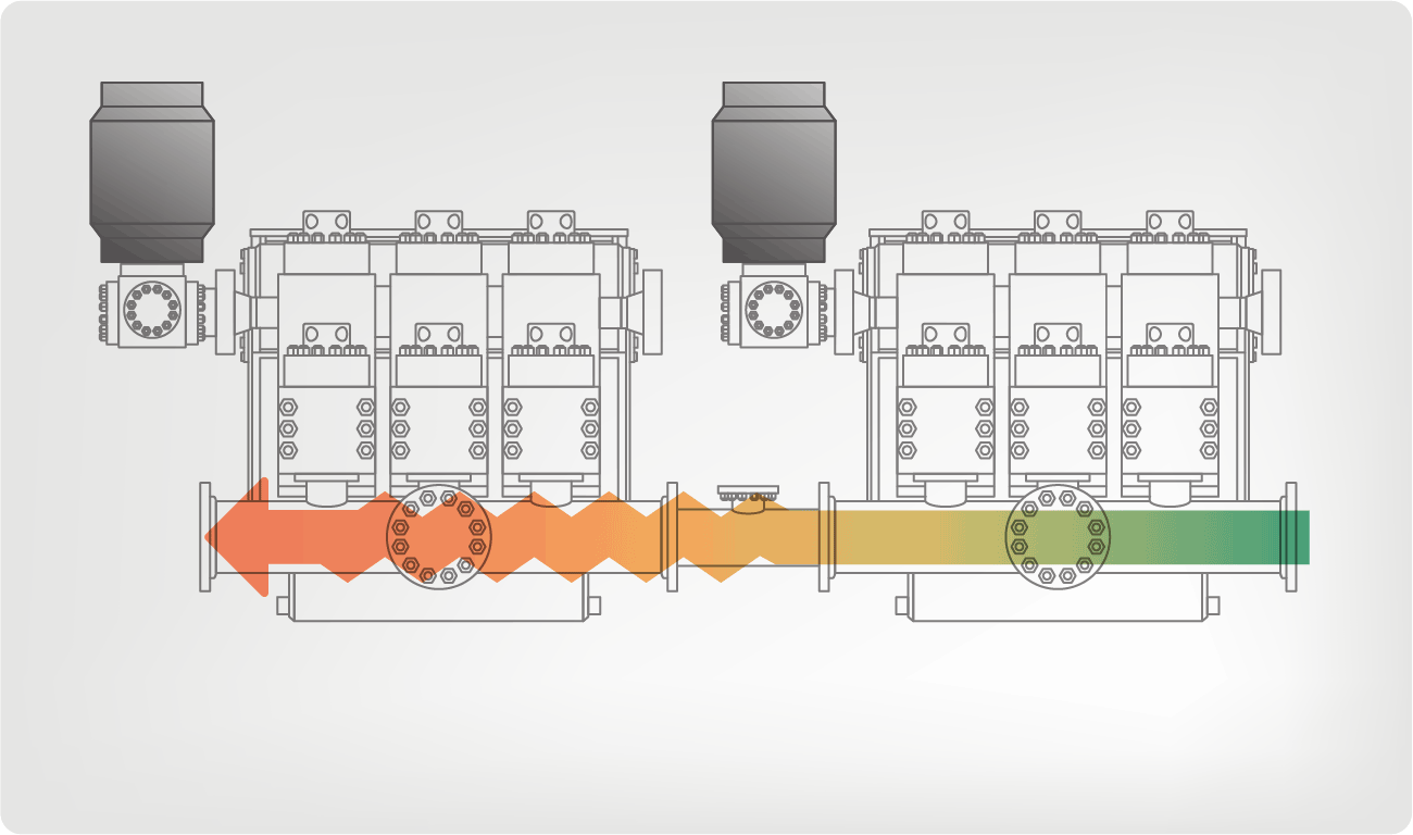
The isolation eliminates pump chatter, and because the reciprocating pump’s negative energies never reach the charge pump, the pump’s expendable life is extended.
Investing in suction stabilizers will ensure your pumps operate consistently and efficiently. They can also prevent most challenges related to pressure surges or pulsations in the most difficult piping environments.
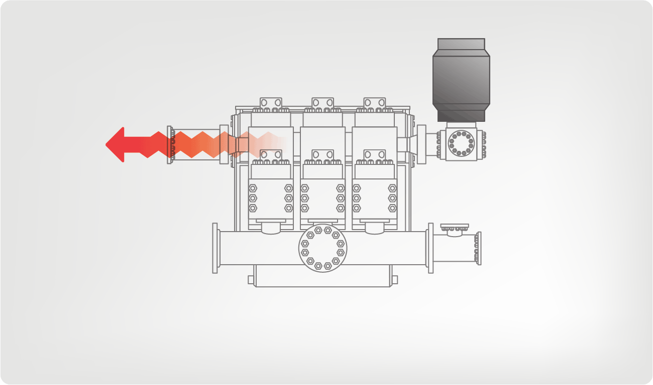
Sigma Drilling Technologies’ Charge Free Suction Stabilizer is recommended for installation. If rigs have gas-charged cartridges installed in the suction stabilizers on the rig, another suggested upgrade is the Charge Free Conversion Kits.

A well-placed suction stabilizer can also prevent pump chatter. Pump chatter occurs when energy is exchanged between the quick opening and closing of the reciprocating pump’s valves and the hammer effect from the centrifugal pump. Pump isolation with suction stabilizers is achieved when the charge pumps are isolated from reciprocating pumps and vice versa. The results are a smooth flow of pumped media devoid of agitating energies present in the pumped fluid.
Suction stabilizer units can mitigate most of the challenges related to pulsations or pressure surges, even in the most complex piping conditions. The resulting benefits prevent expensive unplanned downtime and decrease costs and inconvenience associated with system replacements and repairs.

This website is using a security service to protect itself from online attacks. The action you just performed triggered the security solution. There are several actions that could trigger this block including submitting a certain word or phrase, a SQL command or malformed data.

Cavitation is an undesirable condition that reduces pump efficiency and leads to excessive wear and damage to pump components. Factors that can contribute to cavitation, such as fluid velocity and pressure, can sometimes be attributed to an inadequate mud system design and/or the diminishing performance of the mud pump’s feed system.
When a mud pump has entered full cavitation, rig crews and field service technicians will see the equipment shaking and hear the pump “knocking,” which typically sounds like marbles and stones being thrown around inside the equipment. However, the process of cavitation starts long before audible signs reveal themselves – hence the name “the silent killer.”
Mild cavitation begins to occur when the mud pump is starved for fluid. While the pump itself may not be making noise, damage is still being done to the internal components of the fluid end. In the early stages, cavitation can damage a pump’s module, piston and valve assembly.
The imperceptible but intense shock waves generated by cavitation travel directly from the fluid end to the pump’s power end, causing premature vibrational damage to the crosshead slides. The vibrations are then passed onto the shaft, bull gear and into the main bearings.
If not corrected, the vibrations caused by cavitation will work their way directly to critical power end components, which will result in the premature failure of the mud pump. A busted mud pump means expensive downtime and repair costs.
To stop cavitation before it starts, install and tune high-speed pressure sensors on the mud suction line set to sound an alarm if the pressure falls below 30 psi.
Although the pump may not be knocking loudly when cavitation first presents, regular inspections by a properly trained field technician may be able to detect moderate vibrations and slight knocking sounds.
Gardner Denver offers Pump University, a mobile classroom that travels to facilities and/or drilling rigs and trains rig crews on best practices for pumping equipment maintenance.
Severe cavitation will drastically decrease module life and will eventually lead to catastrophic pump failure. Along with downtime and repair costs, the failure of the drilling pump can also cause damage to the suction and discharge piping.
When a mud pump has entered full cavitation, rig crews and field service technicians will see the equipment shaking and hear the pump ‘knocking’… However, the process of cavitation starts long before audible signs reveal themselves – hence the name ‘the silent killer.’In 2017, a leading North American drilling contractor was encountering chronic mud system issues on multiple rigs. The contractor engaged in more than 25 premature module washes in one year and suffered a major power-end failure.
Gardner Denver’s engineering team spent time on the contractor’s rigs, observing the pumps during operation and surveying the mud system’s design and configuration.
The engineering team discovered that the suction systems were undersized, feed lines were too small and there was no dampening on the suction side of the pump.
There were also issues with feed line maintenance – lines weren’t cleaned out on a regular basis, resulting in solids from the fluid forming a thick cake on the bottom of the pipe, which further reduced its diameter.
Following the implementation of these recommendations, the contractor saw significant performance improvements from the drilling pumps. Consumables life was extended significantly, and module washes were reduced by nearly 85%.
Although pump age does not affect its susceptibility to cavitation, the age of the rig can. An older rig’s mud systems may not be equipped for the way pumps are run today – at maximum horsepower.
This rig features a Mission 4-by-5 centrifugal pump. Courtesy of Higgins Rig Co.Returning to the water well industry when I joined Schramm Inc. last year, I knew that expanding my mud pump knowledge was necessary to represent the company"s mud rotary drill line properly. One item new to me was the centrifugal mud pump. What was this pump that a number of drillers were using? I had been trained that a piston pump was the only pump of any ability.
As I traveled and questioned drillers, I found that opinions of the centrifugal pumps varied. "Best pump ever built," "What a piece of junk" and "Can"t drill more than 200 feet with a centrifugal" were typical of varying responses. Because different opinions had confused the issue, I concluded my discussions and restarted my education with a call to a centrifugal pump manufacturer. After that conversation, I went back to the field to continue my investigation.
For the past eight months, I have held many discussions and conducted field visits to understand the centrifugal pump. As a result, my factual investigation has clearly proved that the centrifugal pump has a place in mud rotary drilling. The fact also is clear that many drilling contractors do not understand the correct operational use of the pump. Following are the results of my work in the field.
High up-hole velocity - High pump flow (gpm) moves cuttings fast. This works well with lower viscosity muds - reducing mud expense, mixing time and creating shorter settling times.
Able to run a desander - The centrifugal"s high volume enables a desander to be operated off the pump discharge while drilling without adding a dedicated desander pump.
6. Sticky clays will stall a centrifugal pump"s flow. Be prepared to reduce your bit load in these conditions and increase your rpm if conditions allow. Yes, clays can be drilled with a centrifugal pump.
7. Centrifugal pumps cannot pump muds over 9.5 lbs./gal. Centrifugal pumps work best with a 9.0 lbs./gal. mud weight or less. High flow rate move cuttings, not heavy mud.
The goal of this article has been to increase awareness of the value of the centrifugal pump and its growing use. Although the centrifugal pump is not flawless, once its different operating techniques are understood, drilling programs are being enhanced with the use of this pump.
If you wish to learn more, please talk directly to centrifugal pump users. Feel free to call me at 314-909-8077 for a centrifugal pump user list. These drillers will gladly share their centrifugal pump experiences.
Discharge Head: This is the vertical distance that you are able to pump liquid. For example, if your pump is rated for a maximum head of 18 feet, this does not mean that you are restricted to 18 feet of pipe. You can use 300 feet, so long as the final discharge point is not higher than 18 feet above the liquid being pumped.
Suction Lift: This is the vertical distance that the pump can be above the liquid source. Typically, atmospheric pressure limits vertical suction lift of pumps to 25 feet at sea level. This does not mean that you are limited to 25 feet of pipe. You could use upwards of 300 feet of suction pipe, so long as the liquid source is not lower than 25 feet below the pump center line.
An innovative product policy and continuous advancement of essential design features make this pump a powerful, yet economical standard unit with a broad range of applications.
Professional China Mud Pump - BNS series Single Stage, End Suction Norm Centrifugal pumps – Beken, The product will supply to all over the world, such as: , , ,

Centrifugal pumps basically consist of a stationary pump casing and an impeller mounted on a rotating shaft. The pump casing provides a pressure boundary for the pump and contains channels to properly direct the suction and discharge flow. The pump casing has suction and discharge penetrations for the main flow path of the pump and normally has small drain and vent fittings to remove gases trapped in the pump casing or to drain the pump casing for maintenance.
Some centrifugal pumps contain diffusers. A diffuser is a set of stationary vanes that surround the impeller. The purpose of the diffuser is to increase the efficiency of the centrifugal pump by allowing a more gradual expansion and less turbulent area for the liquid to reduce in velocity. The diffuser vanes are designed in a manner that the liquid exiting the impeller will encounter an everincreasing flow area as it passes through the diffuser. This increase in flow area causes a reduction in flow velocity, converting kinetic energy into flow pressure.
Impellers of pumps are classified based on the number of points that the liquid can enter the impeller and also on the amount of webbing between the impeller blades.
Impellers can be either single-suction or double-suction. A single-suction impeller allows liquid to enter the center of the blades from only one direction. A double-suction impeller allows liquid to enter the center of the impeller blades from both sides simultaneously. Figure 4 shows simplified diagrams of single and double-suction impellers.
The impeller sometimes contains balancing holes that connect the space around the hub to the suction side of the impeller. The balancing holes have a total cross-sectional area that is considerably greater than the cross-sectional area of the annular space between the wearing ring and the hub. The result is suction pressure on both sides of the impeller hub, which maintains a hydraulic balance of axial thrust.
Centrifugal pumps can be classified based on the manner in which fluid flows through the pump. The manner in which fluid flows through the pump is determined by the design of the pump casing and the impeller. The three types of flow through a centrifugal pump are radial flow, axial flow, and mixed flow.
A centrifugal pump with a single impeller that can develop a differential pressure of more than 150 psid between the suction and the discharge is difficult and costly to design and construct. A more economical approach to developing high pressures with a single centrifugal pump is to include multiple impellers on a common shaft within the same pump casing. Internal channels in the pump casing route the discharge of one impeller to the suction of another impeller. Figure 9 shows a diagram of the arrangement of the impellers of a four-stage pump. The water enters the pump from the top left and passes through each of the four impellers in series, going from left to right. The water goes from the volute surrounding the discharge of one impeller to the suction of the next impeller.
Centrifugal pumps vary in design and construction from simple pumps with relatively few parts to extremely complicated pumps with hundreds of individual parts. Some of the most common components found in centrifugal pumps are wearing rings, stuffing boxes, packing, and lantern rings. These components are shown in Figure 10 and described on the following pages.
Some wear or erosion will occur at the point where the impeller and the pump casing nearly come into contact. This wear is due to the erosion caused by liquid leaking through this tight clearance and other causes. As wear occurs, the clearances become larger and the rate of leakage increases. Eventually, the leakage could become unacceptably large and maintenance would be required on the pump.
To minimize the cost of pump maintenance, many centrifugal pumps are designed with wearing rings. Wearing rings are replaceable rings that are attached to the impeller and/or the pump casing to allow a small running clearance between the impeller and the pump casing without causing wear of the actual impeller or pump casing material. These wearing rings are designed to be replaced periodically during the life of a pump and prevent the more costly replacement of the impeller or the casing.
In almost all centrifugal pumps, the rotating shaft that drives the impeller penetrates the pressure boundary of the pump casing. It is important that the pump is designed properly to control the amount of liquid that leaks along the shaft at the point that the shaft penetrates the pump casing. There are many different methods of sealing the shaft penetration of the pump casing. Factors considered when choosing a method include the pressure and temperature of the fluid being pumped, the size of the pump, and the chemical and physical characteristics of the fluid being pumped.
One of the simplest types of shaft seal is the stuffing box. The stuffing box is a cylindrical space in the pump casing surrounding the shaft. Rings of packing material are placed in this space. Packing is material in the form of rings or strands that is placed in the stuffing box to form a seal to control the rate of leakage along the shaft. The packing rings are held in place by a gland. The gland is, in turn, held in place by studs with adjusting nuts. As the adjusting nuts are tightened, they move the gland in and compress the packing. This axial compression causes the packing to expand radially, forming a tight seal between the rotating shaft and the inside wall of the stuffing box.
The high speed rotation of the shaft generates a significant amount of heat as it rubs against the packing rings. If no lubrication and cooling are provided to the packing, the temperature of the packing increases to the point where damage occurs to the packing, the pump shaft, and possibly nearby pump bearings. Stuffing boxes are normally designed to allow a small amount of controlled leakage along the shaft to provide lubrication and cooling to the packing. The leakage rate can be adjusted by tightening and loosening the packing gland.
It is not always possible to use a standard stuffing box to seal the shaft of a centrifugal pump. The pump suction may be under a vacuum so that outward leakage is impossible or the fluid may be too hot to provide adequate cooling of the packing. These conditions require a modification to the standard stuffing box.
One method of adequately cooling the packing under these conditions is to include a lantern ring. A lantern ring is a perforated hollow ring located near the center of the packing box that receives relatively cool, clean liquid from either the discharge of the pump or from an external source and distributes the liquid uniformly around the shaft to provide lubrication and cooling. The fluid entering the lantern ring can cool the shaft and packing, lubricate the packing, or seal the joint between the shaft and packing against leakage of air into the pump in the event the pump suction pressure is less than that of the atmosphere.
In some situations, packing material is not adequate for sealing the shaft. One common alternative method for sealing the shaft is with mechanical seals. Mechanical seals consist of two basic parts, a rotating element attached to the pump shaft and a stationary element attached to the pump casing. Each of these elements has a highly polished sealing surface. The polished faces of the rotating and stationary elements come into contact with each other to form a seal that prevents leakage along the shaft.
A diffuser increases the efficiency of a centrifugal pump by allowing a more gradual expansion and less turbulent area for the liquid to slow as the flow area expands.
Wearing rings are replaceable rings that are attached to the impeller and/or the pump casing to allow a small running clearance between the impeller and pump casing without causing wear of the actual impeller or pump casing material.
Many centrifugal pumps are designed in a manner that allows the pump to operate continuously for months or even years. These centrifugal pumps often rely on the liquid that they are pumping to provide cooling and lubrication to the pump bearings and other internal components of the pump. If flow through the pump is stopped while the pump is still operating, the pump will no longer be adequately cooled and the pump can quickly become damaged. Pump damage can also result from pumping a liquid whose temperature is close to saturated conditions.
The flow area at the eye of the pump impeller is usually smaller than either the flow area of the pump suction piping or the flow area through the impeller vanes. When the liquid being pumped enters the eye of a centrifugal pump, the decrease in flow area results in an increase in flow velocity accompanied by a decrease in pressure. The greater the pump flow rate, the greater the pressure drop between the pump suction and the eye of the impeller. If the pressure drop is large enough, or if the temperature is high enough, the pressure drop may be sufficient to cause the liquid to flash to vapor when the local pressure falls below the saturation pressure for the fluid being pumped. Any vapor bubbles formed by the pressure drop at the eye of the impeller are swept along the impeller vanes by the flow of the fluid. When the bubbles enter a region where local pressure is greater than saturation pressure farther out the impeller vane, the vapor bubbles abruptly collapse. This process of the formation and subsequent collapse of vapor bubbles in a pump is called cavitation.
Cavitation in a centrifugal pump has a significant effect on pump performance. Cavitation degrades the performance of a pump, resulting in a fluctuating flow rate and discharge pressure. Cavitation can also be destructive to pumps internal components. When a pump cavitates, vapor bubbles form in the low pressure region directly behind the rotating impeller vanes. These vapor bubbles then move toward the oncoming impeller vane, where they collapse and cause a physical shock to the leading edge of the impeller vane. This physical shock creates small pits on the leading edge of the impeller vane. Each individual pit is microscopic in size, but the cumulative effect of millions of these pits formed over a period of hours or days can literally destroy a pump impeller. Cavitation can also cause excessive pump vibration, which could damage pump bearings, wearing rings, and seals.
A small number of centrifugal pumps are designed to operate under conditions where cavitation is unavoidable. These pumps must be specially designed and maintained to withstand the small amount of cavitation that occurs during their operation. Most centrifugal pumps are not designed to withstand sustained cavitation.
Noise is one of the indications that a centrifugal pump is cavitating. A cavitating pump can sound like a can of marbles being shaken. Other indications that can be observed from a remote operating station are fluctuating discharge pressure, flow rate, and pump motor current. Methods to stop or prevent cavitation are presented in the following paragraphs.
To avoid cavitation in centrifugal pumps, the pressure of the fluid at all points within the pump must remain above saturation pressure. The quantity used to determine if the pressure of the liquid being pumped is adequate to avoid cavitation is the net positive suction head (NPSH). The net positive suction head available (NPSHA) is the difference between the pressure at the suction of the pump and the saturation pressure for the liquid being pumped. The net positive suction head required (NPSHR) is the minimum net positive suction head necessary to avoid cavitation.
The condition that must exist to avoid cavitation is that the net positive suction head available must be greater than or equal to the net positive suction head required. This requirement can be stated mathematically as shown below.
When a centrifugal pump is taking suction from a tank or other reservoir, the pressure at the suction of the pump is the sum of the absolute pressure at the surface of the liquid in the tank plus the pressure due to the elevation difference between the surface of liquid in the tank and the pump suction less the head losses due to friction in the suction line from the tank to the pump.
If a centrifugal pump is cavitating, several changes in the system design or operation may be necessary to increase the NPSHA above the NPSHR and stop the cavitation. One method for increasing the NPSHA is to increase the pressure at the suction of the pump. For example, if a pump is taking suction from an enclosed tank, either raising the level of the liquid in the tank or increasing the pressure in the space above the liquid increases suction pressure.
It is also possible to increase the NPSHA by decreasing the temperature of the liquid being pumped. Decreasing the temperature of the liquid decreases the saturation pressure, causing NPSHA to increase. Recall from the previous module on heat exchangers that large steam condensers usually subcool the condensate to less than the saturation temperature, called condensate depression, to prevent cavitation in the condensate pumps.
If the head losses in the pump suction piping can be reduced, the NPSHA will be increased. Various methods for reducing head losses include increasing the pipe diameter, reducing the number of elbows, valves, and fittings in the pipe, and decreasing the length of the pipe.
It may also be possible to stop cavitation by reducing the NPSHR for the pump. The NPSHR is not a constant for a given pump under all conditions, but depends on certain factors. Typically, the NPSHR of a pump increases significantly as flow rate through the pump increases. Therefore, reducing the flow rate through a pump by throttling a discharge valve decreases NPSHR. NPSHR is also dependent upon pump speed. The faster the impeller of a pump rotates, the greater the NPSHR. Therefore, if the speed of a variable speed centrifugal pump is reduced, the NPSHR of the pump decreases. However, since a pump’s flow rate is most often dictated by the needs of the system on which it is connected, only limited adjustments can be made without starting additional parallel pumps, if available.
The net positive suction head required to prevent cavitation is determined through testing by the pump manufacturer and depends upon factors including type of impeller inlet, impeller design, pump flow rate, impeller rotational speed, and the type of liquid being pumped. The manufacturer typically supplies curves of NPSHR as a function of pump flow rate for a particular liquid (usually water) in the vendor manual for the pump.
For a given centrifugal pump operating at a constant speed, the flow rate through the pump is Figure 11 Centrifugal Pump Characteristic Curve dependent upon the differential pressure or head developed by the pump. The lower the pump head, the higher the flow rate. A vendor manual for a specific pump usually contains a curve of pump flow rate versus pump head called a pump characteristic curve. After a pump is installed in a system, it is usually tested to ensure that the flow rate and head of the pump are within the required specifications. A typical centrifugal pump characteristic curve is shown in Figure 11.
A centrifugal pump is dead-headed when it is operated with no flow through it, for example, with a closed discharge valve or against a seated check valve. If the discharge valve is closed and there is no other flow path available to the pump, the impeller will churn the same volume of water as it rotates in the pump casing. This will increase the temperature of the liquid (due to friction) in the pump casing to the point that it will flash to vapor. The vapor can interrupt the cooling flow to the pump’s packing and bearings, causing excessive wear and heat. If the pump is run in this condition for a significant amount of time, it will become damaged.
When a centrifugal pump is installed in a system such that it may be subjected to periodic shutoff head conditions, it is necessary to provide some means of pump protection. One method for protecting the pump from running dead-headed is to provide a recirculation line from the pump discharge line upstream of the discharge valve, back to the pump’s supply source. The recirculation line should be sized to allow enough flow through the pump to prevent overheating and damage to the pump. Protection may also be accomplished by use of an automatic flow control device.
Centrifugal pumps must also be protected from runout. Runout can lead to cavitation and can also cause overheating of the pump’s motor due to excessive currents. One method for ensuring that there is always adequate flow resistance at the pump discharge to prevent excessive flow through the pump is to place an orifice or a throttle valve immediately downstream of the pump discharge. Properly designed piping systems are very important to protect from runout.
Gas binding of a centrifugal pump is a condition where the pump casing is filled with gases or vapors to the point where the impeller is no longer able to contact enough fluid to function correctly. The impeller spins in the gas bubble, but is unable to force liquid through the pump. This can lead to cooling problems for the pump’s packing and bearings.
Centrifugal pumps are designed so that their pump casings are completely filled with liquid during pump operation. Most centrifugal pumps can still operate when a small amount of gas accumulates in the pump casing, but pumps in systems containing dissolved gases that are not designed to be self-venting should be periodically vented manually to ensure that gases do not build up in the pump casing.
Most centrifugal pumps are not self-priming. In other words, the pump casing must be filled with liquid before the pump is started, or the pump will not be able to function. If the pump casing becomes filled with vapors or gases, the pump impeller becomes gas-bound and incapable of pumping. To ensure that a centrifugal pump remains primed and does not become gas-bound, most centrifugal pumps are located below the level of the source from which the pump is to take its suction. The same effect can be gained by supplying liquid to the pump suction under pressure supplied by another pump placed in the suction line.
Damage to pump impeller, bearings, wearing rings, and sealsTo avoid pump cavitation, the net positive suction head available must be greater than the net positive suction head required.
Gas binding of a centrifugal pump is a condition where the pump casing is filled with gases or vapors to the point where the impeller is no longer able to contact enough fluid to function correctly.
Centrifugal pumps are protected from runout by placing an orifice or throttle valve immediately downstream of the pump discharge and through proper piping system design.
A positive displacement pump is one in which a definite volume of liquid is delivered for each cycle of pump operation. This volume is constant regardless of the resistance to flow offered by the system the pump is in, provided the capacity of the power unit driving the pump or pump component strength limits are not exceeded. The positive displacement pump delivers liquid in separate volumes with no delivery in between, although a pump having several chambers may have an overlapping delivery among individual chambers, which minimizes this effect. The positive displacement pump differs from centrifugal pumps, which deliver a continuous flow for any given pump speed and discharge resistance.
Positive displacement pumps can be grouped into three basic categories based on their design and operation. The three groups are reciprocating pumps, rotary pumps, and diaphragm pumps.
During the suction stroke, the piston moves to the left, causing the check valve in the suction Figure 12 Reciprocating Positive Displacement Pump Operation line between the reservoir and the pump cylinder to open and admit water from the reservoir. During the discharge stroke, the piston moves to the right, seating the check valve in the suction line and opening the check valve in the discharge line. The volume of liquid moved by the pump in one cycle (one suction stroke and one discharge stroke) is equal to the change in the liquid volume of the cylinder as the piston moves from its farthest left position to its farthest right position.
Reciprocating positive displacement pumps are generally categorized in four ways: direct-acting or indirect-acting; simplex or duplex; single-acting or double-acting; and power pumps.
Some reciprocating pumps are powered by prime movers that also have reciprocating motion, such as a reciprocating pump powered by a reciprocating steam piston. The piston rod of the steam piston may be directly connected to the liquid piston of the pump or it may be indirectly connected with a beam or linkage. Direct-acting pumps have a plunger on the liquid (pump) end that is directly driven by the pump rod (also the piston rod or extension thereof) and carries the piston of the power end. Indirect-acting pumps are driven by means of a beam or linkage connected to and actuated by the power piston rod of a separate reciprocating engine.
A simplex pump, sometimes referred to as a single pump, is a pump having a single liquid (pump) cylinder. A duplex pump is the equivalent of two simplex pumps placed side by side on the same foundation.
The driving of the pistons of a duplex pump is arranged in such a manner that when one piston is on its upstroke the other piston is on its downstroke, and vice versa. This arrangement doubles the capacity of the duplex pump compared to a simplex pump of comparable design.
A single-acting pump is one that takes a suction, filling the pump cylinder on the stroke in only one direction, called the suction stroke, and then forces the liquid out of the cylinder on the return stroke, called the discharge stroke. A double-acting pump is one that, as it fills one end of the liquid cylinder, is discharging liquid from the other end of the cylinder. On the return stroke, the end of the cylinder just emptied is filled, and the end just filled is emptied. One possible arrangement for single-acting and double-acting pumps is shown in Figure 13.
Power pumps typically have high efficiency and are capable of developing very high pressures. Figure 13 Single-Acting and Double-Acting Pumps They can be driven by either electric motors or turbines. They are relatively expensive pumps and can rarely be justified on the basis of efficiency over centrifugal pumps. However, they are frequently justified over steam reciprocating pumps where continuous duty service is needed due to the high steam requirements of direct-acting steam pumps.
In general, the effective flow rate of reciprocating pumps decreases as the viscosity of the fluid being pumped increases because the speed of the pump must be reduced. In contrast to centrifugal pumps, the differential pressure generated by reciprocating pumps is independent of fluid density. It is dependent entirely on the amount of force exerted on the piston. For more information on viscosity, density, and positive displacement pump theory, refer to the handbook on Thermodynamics, Heat Transfer, and Fluid Flow.
Rotary pumps operate on the principle that a rotating vane, screw, or gear traps the liquid in the suction side of the pump casing and forces it to the discharge side of the casing. These pumps are essentially self-priming due to their capability of removing air from suction lines and producing a high suction lift. In pumps designed for systems requiring high suction lift and selfpriming features, it is essential that all clearances between rotating parts, and between rotating and stationary parts, be kept to a minimum in order to reduce slippage. Slippage is leakage of fluid from the discharge of the pump back to its suction.
Due to the close clearances in rotary pumps, it is necessary to operate these pumps at relatively low speed in order to secure reliable operation and maintain pump capacity over an extended period of time. Otherwise, the erosive action due to the high velocities of the liquid passing through the narrow clearance spaces would soon cause excessive wear and increased clearances, resulting in slippage.
There are many types of positive displacement rotary pumps, and they are normally grouped into three basic categories that include gear pumps, screw pumps, and moving vane pumps.
There are several variations of gear pumps. The simple gear pump shown in Figure 14 consists of two spur gears meshing together and revolving in opposite directions within a casing. Only a few thousandths of an inch clearance exists between the case and the gear faces and teeth extremities. Any liquid that fills the space bounded by two successive gear teeth and the case must follow along with the teeth as they revolve. When the gear teeth mesh with the teeth of the other gear, the space between the teeth is reduced, and the entrapped liquid is forced out the pump discharge pipe. As the gears revolve and the teeth disengage, the space again opens on the suction side of the pump, trapping new quantities of liquid and carrying it around the pump case to the discharge. As liquid is carried away from the suction side, a lower pressure is created, which draws liquid in through the suction line.
With the large number of teeth usually employed on the gears, the discharge is relatively smooth and continuous, with small quantities of liquid being delivered to the discharge line in rapid succession. If designed with fewer teeth, the space between the teeth is greater and the capacity increases for a given speed; however, the tendency toward a pulsating discharge increases. In all simple gear pumps, power is applied to the shaft of one of the gears, which transmits power to the driven gear through their meshing teeth.
There are no valves in the gear pump to cause friction losses as in the reciprocating pump. The high impeller velocities, with resultant friction losses, are not required as in the centrifugal pump. Therefore, the gear pump is well suited for handling viscous fluids such as fuel and lubricating oils.
There are two types of gears used in gear pumps in addition to the simple spur gear. One type is the helical gear. A helix is the curve produced when a straight line moves up or down the surface of a cylinder. The other type is the herringbone gear. A herringbone gear is composed of two helixes spiraling in different directions from the center of the gear. Spur, helical, and herringbone gears are shown in Figure 15.
The helical gear pump has advantages over the simple spur gear. In a spur gear, the entire length of the gear tooth engages at the same time. In a helical gear, the point of engagement moves along the length of the gear tooth as the gear rotates. This makes the helical gear operate with a steadier discharge pressure and fewer pulsations than a spur gear pump.
The herringbone gear pump is also a modification of the simple gear pump. Its principal difference in operation from the simple spur gear pump is that the pointed center section of the space between two teeth begins discharging before the divergent outer ends of the preceding space complete discharging. This overlapping tends to provide a steadier discharge pressure. The power transmission from the driving to the driven gear is also smoother and quieter.
The lobe type pump shown in Figure 16 is another variation of the simple gear pump. It is considered as a simple gear pump having only two or three teeth per rotor; otherwise, its operation or the explanation of the function of its parts is no different. Some designs of lobe pumps are fitted with replaceable gibs, that is, thin plates carried in grooves at the extremity of each lobe where they make contact with the casing. The gib promotes tightness and absorbs radial wear.
There are many variations in the design of the screw type positive displacement, rotary pump. The primary differences consist of the number of intermeshing screws involved, the pitch of the screws, and the general direction of fluid flow. Two common designs are the two-screw, low-pitch, double-flow pump and the three-screw, high-pitch, double-flow pump.
The complete assembly and the usual flow Figure 18 Three-Screw, High-Pitch, Screw Pump path are shown in Figure 17. Liquid is trapped at the outer end of each pair of screws. As the first space between the screw threads rotates away from the opposite screw, a one-turn, spiral-shaped quantity of liquid is enclosed when the end of the screw again meshes with the opposite screw. As the screw continues to rotate, the entrapped spiral turns of liquid slide along the cylinder toward the center discharge space while the next slug is being entrapped. Each screw functions similarly, and each pair of screws discharges an equal quantity of liquid in opposed streams toward the center, thus eliminating hydraulic thrust. The removal of liquid from the suction end by the screws produces a reduction in pressure, which draws liquid through the suction line.
The three-screw, high-pitch, screw pump, shown in Figure 18, has many of the same elements as the two-screw, low-pitch, screw pump, and their operations are similar. Three screws, oppositely threaded on each end, are employed. They rotate in a triple cylinder, the two outer bores of which overlap the center bore. The pitch of the screws is much higher than in the low pitch screw pump; therefore, the center screw, or power rotor, is used to drive the two outer idler rotors directly without external timing gears. Pedestal bearings at the base support the weight of the rotors and maintain their axial position. The liquid being pumped enters the suction opening, flows through passages around the rotor housing, and through the screws from each end, in opposed streams, toward the center discharge. This eliminates unbalanced hydraulic thrust. The screw pump is used for pumping viscous fluids, usually lubricating, hydraulic, or fuel oil.
Positive displacement pumps deliver a definite volume of Positive Displacement Pump Characteristic Curve liquid for each cycle of pump operation. Therefore, the only factor that effects flow rate in an ideal positive displacement pump is the speed at which it operates. The flow resistance of the system in which the pump is operating will not effect the flow rate through the pump. Figure 21 shows the characteristic curve for a positive displacement pump.
The dashed line in Figure 21 shows actual positive displacement pump performance. This line reflects the fact that as the discharge pressure of the pump increases, some amount of liquid will leak from the discharge of the pump back to the pump suction, reducing the effective flow rate of the pump. The rate at which liquid leaks from the pump discharge to its suction is called slippage.
Positive displacement pumps are normally fitted with relief valves on the upstream side of their discharge valves to protect the pump and its discharge piping from overpressurization. Positive displacement pumps will discharge at the pressure required by the system they are supplying. The relief valve prevents system and pump damage if the pump discharge valve is shut during pump operation or if any other occurrence such as a clogged strainer blocks system flow.
The important information in this chapter is summarized below.The flow delivered by a centrifugal pump during one revolution of the impeller depends upon the head against which the pump is operating. The positive displacement pump delivers a definite volume of fluid for each cycle of pump operation regardless of the head against which the pump is operating.
Moving vane pump Diaphragm pumpAs the viscosity of a liquid increases, the maximum speed at which a reciprocating positive displacement pump can properly operate decreases. Therefore, as viscosity increases, the maximum flow rate through the pump decreases.

It’s no secret that a pump that runs at peak efficiency uses less fuel, experiences less downtime and costs less to operate. The time you spend maintaining your pump is actually an investment in its lifetime performance and value. In fact, there are many ways that a diligently maintained pump can reduce your costs, while increasing efficiency. For instance, by ensuring your pump investment brings an ease-of-service design, the time you spend on maintenance can be significantly minimized.
Using the information below, see if you can identify some of your own trouble spots, and uncover potential solutions to get you back on the road to good pump health – boosting profits along the way.
Take notice of the discharge flow. Has it visibly decreased? Is it taking your pump longer to do the same job than it used to? The slowed flow may be caused by a collapsed suction hose lining, a leaking gasket, a plugged suction line or a damaged or worn impeller or wear plate.
To determine the cause of any decrease in flow, the discharge pressure and the suction vacuum should be measured while the pump is operating. If the pump discharge pressure and suction vacuum were measured at start up, the latest readings should be compared to the originally recorded readings. When troubleshooting any pump and system, follow the high abnormal reading taken earlier. A higher than normal discharge pressure reading will indicate a decrease in suction vacuum, and could be a sign of a clogged or partially clogged discharge line, a closed valve, air unable to evacuate or any obstruction outboard of the point the gauge was installed into the discharge line. It is common practice to install gauges approximately two to four pipe diameters from the pump.
Both gauges can also decrease. If they do, the problem is located between the installed locations of the gauges. In this case, the problem is within the pump. A clog at the eye of the impeller, wear, wide clearances and air induced into the suction line could all cause both gauge readings to decrease. Note that gauge readings almost always teeter back and forth. But again, follow the problem to the highest abnormal gauge reading.
The pump isn’t re-priming as rapidly as it once did. Most commonly, slower re-prime can be attributed to excessive face clearance. If this is not the cause of your slowdown, check the following:
A maximum vacuum check can be performed to determine the location of the problem. Fill the pump with the minimum amount of water than what the volute casing normally retains for re-priming. To do so, simply remove the suction flap valve, priming the volute casing and energizing the pump. After the pump achieves dynamic operation, turn the pump off and allow the liquid in the pump to return to the sump.
Whatever product remains in the volute casing is the minimum left for a re-prime cycle. Install a vacuum gauge on the suction side of the pump and close a valve in the suction line outboard of the gauge. If there are no valves in the suction line, a solid gasket without an inside diameter hole may be installed in a pipe joint to create a “valve” effect. Energize the pump and inspect the vacuum gauge. The pump will pull a vacuum against the closed valve or solid gasket. This reading is the equivalent to the pump’s lift capabilities. If a vacuum gauge calibrated in inches of mercury (Hg) is used, multiply that reading by 1.13 to convert to feet of water.
If your pump sounds like a bunch of marbles rattling in a can, this may be an indication of cavitation – and could be caused by a suction lift that’s too high, a suction hose that’s too long, plugged or has a collapsed lining, a clogged strainer, a combination of any of these, or perhaps a problem on the discharge side of the pump. Failing bearings can also cause excessive noise. Noise should be qualified as mechanical or hydraulic noise. Run the pump briefly without water. If the noise is no longer present, the noise is one of a hydraulic nature. If the noise is present after removing the product, the noise is mechanical. Again, a quality set of gauge readings will direct your attention to the problem side of the system if the noise is deemed to be a hydraulic noise.
If a pump’s suction check valve is clogged, the strainer may be too large or too small, or face clearance could be too wide. Alternatively, the strainer may be stuck in mud, plugging the suction side.
In this case, very likely, the flow of liquid into or out of the pump is being restricted. Improper impeller clearance could be slowing re-priming, the suction strainer or recirculation port in the volute casing may be clogged or the pump’s ability to handle air through an air release line, air release valve or open ended discharge line may be obstructed. Never open a hot pump. Allow the pump to cool to the touch prior to opening. Even after cooling, there may be lingering pressure inside the volute casing.
Using a vacuum gauge, make sure that the suction line, fittings and pipe plugs are airtight. Pumps, such as Gorman-Rupp pumps typically have a tapped hole for easy connection of a vacuum gauge. Use pipe dope to seal gauge threads and pipe plugs. A vacuum gauge will fluctuate or give erratic readings while handling air during operation. At shut down, the suction gauge reading will display the vertical distance from the gauge tap to the product level. If this vacuum falls off after shut down, atmospheric pressure is entering the suction pipe causing the pump to lose its static lift. Replace the suction flap valve if worn and check for air leaks if the product returns to the sump. Replace leaky seals and badly worn hoses, if necessary.
The rubber lining in a suction hose can pull away from the fabric, causing partial blockage of the line. If the pump develops a high vacuum but low discharge pressure, the hose lining may be blocking suction flow. Gauge readings during operation will be higher than normal with the lining collapsed. To rectify this problem, simply replace the hose. Check the suction strainer. Frequent inspection and cleaning of the suction strainer is particularly important when pumping liquids containing solids. Gauge readings during operation will be higher than normal if debris obstructs the flow through the strainer. Always use the proper size strainer to prevent the pump from clogging.
Check the volute casing, impeller vanes, wear plate or wear rings and attaching hardware. A removable cover plate on the pump allows for quick, easy access when inspection of the impeller and wear plate is needed. These components should be inspected every six months or sooner, depending on pump application because they are subject to faster wear when pumping abrasive liquids and slurries. Gorman-Rupp wear plates and wear rings, for instance, can be replaced without replacing expensive castings. A shut off test can be performed to measure the internal wear. Start the pump and allow it to achieve full flow. Slowly close a discharge valve and record suction and discharge gauge readings. Those reading should equal the maximum pressure noted on the pump performance curve at zero flow.
Pumping efficiency will be reduced if the clearance between impeller and wear plate or wear rings is beyond the recommended limits. If the clearance is less than recommended, components will wear by rubbing, causing excess work for the engine or motor. Check the impeller clearance against the pump manual specifications and adjust it if necessary. A shut off test can be performed to verify not only wear but face clearance as well.
Better pumps are equipped with a double seal, which is lubricated under pressure by a spring-loaded grease cup, or an oil-lubricated seal for long, trouble-free service. Some pumps are equipped with a single seal that is lubricated by the liquid being pumped. Sand or other solids can cause rapid wear of the seal faces. Check and replace the seal if worn. The maximum vacuum test will qualify the integrity of the pump’s seal. Replace the seal liner or shaft sleeve if they have scratches.
Worn bearings can cause the shaft to wobble. Eventually the pump will become noisy and overheat. Worn bearings will reflect higher amperage readings due to the increased wear. Sooner or later it will freeze up and stop. Replace bearings at the first sign of wear to alleviate destructive damaged caused when bearings fail catastrophically.
The pump may not be getting the power it needs to operate efficiently. The engine may need a tune-up, or the motor may need service. Refer to the owner’s manual often for optimum efficiency.
Check air release devices, valves, check valves and shock control devices for proper operation. Old discharge lines are subject to internal rusting and pitting, which cause friction loss and reduce flow by as much as 15%. A discharge gauge reading will increase with the additional losses. Replace badly deteriorated lines.
Mud pump is one of the most critical equipment on the rig; therefore personnel on the rig must have good understanding about it. We’ve tried to find the good training about it but it is very difficult to find until we’ve seen this VDO training and it is a fantastic VDO training about the basic of mud pumps used in the oilfield. Total length of this VDO is about thirteen minutes and it is worth to watch it. You will learn about it so quickly. Additionally, we also add the full detailed transcripts which will acceleate the learning curve of learners.
Powerful mud pumps pick up mud from the suction tank and circulate the mud down hole, out the bit and back to the surface. Although rigs usually have two mud pumps and sometimes three or four, normally they use only one at a time. The others are mainly used as backup just in case one fails. Sometimes however the rig crew may compound the pumps, that is, they may use three or four pumps at the same time to move large volumes of mud when required.
Rigs use one of two types of mud pumps, Triplex pumps or Duplex pumps. Triplex pumps have three pistons that move back-and-forth in liners. Duplex pumps have two pistons move back and forth in liners.
Triplex pumps have many advantages they weight 30% less than a duplex of equal horsepower or kilowatts. The lighter weight parts are easier to handle and therefore easier to maintain. The other advantages include;
• One of the more important advantages of triplex over duplex pumps, is that they can move large volumes of mud at the higher pressure is required for modern deep hole drilling.
Triplex pumps are gradually phasing out duplex units. In a triplex pump, the pistons discharge mud only when they move forward in the liner. Then, when they moved back they draw in mud on the same side of the piston. Because of this, they are also called “single acting.” Single acting triplex pumps, pump mud at a relatively high speeds. Input horsepower ranges from 220 to 2200 or 164 to 1641 kW. Large pumps can pump over 1100 gallons per minute, over 4000 L per minute. Some big pumps have a maximum rated pressure of over 7000 psi over 50,000 kPa with 5 inch/127 mm liners.
Here is a schematic of a triplex pump. It has three pistons each moving in its own liner. It also has three intake valves and three discharge valves. It also has a pulsation dampener in the discharge line.
Look at the piston at left, it has just completed pushing mud out of the liner through the open discharge valve. The piston is at its maximum point of forward travel. The other two pistons are at other positions in their travel and are also pumping mud. But for now, concentrate on the left one to understand how the pump works. The left piston has completed its backstroke drawing in mud through the open intake valve. As the piston moved back it instead of the intake valve off its seat and drew mud in. A strong spring holds the discharge above closed. The left piston has moved forward pushing mud through the now open discharge valve. A strong spring holds the intake valve closed. They left piston has completed its forward stroke they form the length of the liner completely discharging the mud from it. All three pistons work together to keep a continuous flow of mud coming into and out of the pump.
Crewmembers can change the liners and pistons. Not only can they replace worn out ones, they can also install different sizes. Generally they use large liners and pistons when the pump needs to move large volumes of mud at relatively low pressure. They use a small liners and pistons when the pump needs to move smaller volumes of mud at a relatively high pressure.
In a duplex pump, pistons discharge mud on one side of the piston and at the same time, take in mud on the other side. Notice the top piston and the liner. As the piston moves forward, it discharges mud on one side as it draws in mud on the other then as it moves back, it discharges mud on the other side and draws in mud on the side it at had earlier discharge it. Duplex pumps are therefore double acting.
Double acting pumps move more mud on a single stroke than a triplex. However, because of they are double acting they have a seal around the piston rod. This seal keeps them from moving as fast as a triplex. Input horsepower ranges from 190 to 1790 hp or from 142 to 1335 kW. The largest pumps maximum rated working pressure is about 5000 psi, almost 35,000 kPa with 6 inch/152 mm linings.
A mud pump has a fluid end, our end and intake and the discharge valves. The fluid end of the pump contains the pistons with liners which take in or discharge the fluid or mud. The pump pistons draw in mud through the intake valves and push mud out through the discharge valves.
The power end houses the large crankshaft and gear assembly that moves the piston assemblies on the fluid end. Pumps are powered by a pump motor. Large modern diesel/electric rigs use powerful electric motors to drive the pump. Mechanical rigs use chain drives or power bands (belts) from the rig’s engines and compounds to drive the pump.
A pulsation dampener connected to the pump’s discharge line smooths out surges created by the pistons as they discharge mud. This is a standard bladder type dampener. The bladder and the dampener body, separates pressurized nitrogen gas above from mud below. The bladder is made from synthetic rubber and is flexible. When mud discharge pressure presses against the bottom of the bladder, nitrogen pressure above the bladder resists it. This resistance smoothes out the surges of mud leaving the pump.
Here is the latest type of pulsation dampener, it does not have a bladder. It is a sphere about 4 feet or 1.2 m in diameter. It is built into the mud pump’s discharge line. The large chamber is form of mud. It has no moving parts so it does not need maintenance. The mud in the large volume sphere, absorbs this surges of mud leaving the pump.
A suction dampener smooths out the flow of mud entering into the pump. Crewmembers mount it on the triplex mud pump’s suction line. Inside the steel chamber is a air charged rubber bladder or diaphragm. The crew charges of the bladder about 10 to 15 psi/50 to 100 kPa. The suction dampener absorbs surges in the mud pump’s suction line caused by the fast-moving pump pistons. The pistons, constantly starts and stops the mud’s flow through the pump. At the other end of the charging line a suction pumps sends a smooth flow of mud to the pump’s intake. When the smooth flow meets the surging flow, the impact is absorbed by the dampener.
Workers always install a discharge pressure relief valve. They install it on the pump’s discharge side in or near the discharge line. If for some reason too much pressure builds up in the discharge line, perhaps the drill bit or annulus gets plugged, the relief valve opens. That opened above protects the mud pump and system damage from over pressure.
Some rig owners install a suction line relief valve. They install it on top of the suction line near the suction dampener. They mount it on top so that it won’t clog up with mud when the system is shut down. A suction relief valve protects the charging pump and the suction line dampener. A suction relief valve usually has a 2 inch or 50 mm seat opening. The installer normally adjusts it to 70 psi or 500 kPa relieving pressure. If both the suction and the discharged valves failed on the same side of the pump, high back flow or a pressure surge would occur. The high backflow could damage the charging pump or the suction line dampener. The discharge line is a high-pressure line through which the pump moves mud. From the discharge line, the mud goes through the stand pipe and rotary hose to the drill string equipment.


 8613371530291