
mud pump suction line in stock
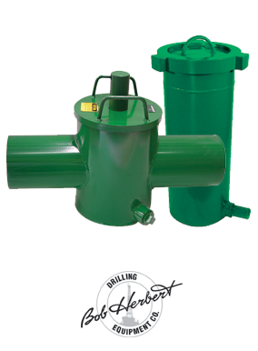
The HURRICANE suction line strainer protects mud pump fluid ends from unwanted debris entering the fluid stream. The strainer is easily cleaned and returned to service in minutes. A variety of end connections are available, including butt weld, flanged or threaded, to install in the suction line of any mud pump. HURRICANE strainers are built to withstand the rough service found on drilling rigs. Inlet / outlet diameters of 4”, 6”, 8”, 10” and 12” are standard. Provide the inlet / outlet size and height D as shown below with any price requests.

-Select-AfghanistanAlbaniaAlgeriaAmerican SamoaAndorraAngolaAnguillaAntigua and BarbudaArgentinaArmeniaArubaAustraliaAustriaAzerbaijan RepublicBahamasBahrainBangladeshBelarusBelgiumBelizeBeninBermudaBhutanBoliviaBosnia and HerzegovinaBotswanaBrazilBritish Virgin IslandsBrunei DarussalamBulgariaBurkina FasoBurundiCambodiaCameroonCanadaCape Verde IslandsCayman IslandsCentral African RepublicChadChileChinaColombiaComorosCook IslandsCosta RicaCyprusCzech RepublicCôte d"Ivoire (Ivory Coast)Democratic Republic of the CongoDenmarkDjiboutiDominicaDominican RepublicEcuadorEgyptEl SalvadorEquatorial GuineaEritreaEstoniaEthiopiaFalkland Islands (Islas Malvinas)FijiFinlandFranceGabon RepublicGambiaGeorgiaGermanyGhanaGibraltarGreeceGreenlandGrenadaGuamGuatemalaGuernseyGuineaGuinea-BissauGuyanaHaitiHondurasHong KongHungaryIcelandIndiaIndonesiaIraqIrelandIsraelItalyJamaicaJapanJerseyJordanKazakhstanKenyaKiribatiKuwaitKyrgyzstanLaosLatviaLebanonLesothoLiberiaLiechtensteinLithuaniaLuxembourgMacauMacedoniaMadagascarMalawiMalaysiaMaldivesMaliMaltaMarshall IslandsMauritaniaMauritiusMayotteMexicoMicronesiaMoldovaMonacoMongoliaMontenegroMontserratMoroccoMozambiqueNamibiaNauruNepalNetherlandsNetherlands AntillesNew ZealandNicaraguaNigerNigeriaNiueNorwayOmanPakistanPalauPanamaPapua New GuineaParaguayPeruPhilippinesPolandPortugalPuerto RicoQatarRepublic of CroatiaRepublic of the CongoRomaniaRwandaSaint HelenaSaint Kitts-NevisSaint LuciaSaint Pierre and MiquelonSaint Vincent and the GrenadinesSan MarinoSaudi ArabiaSenegalSerbiaSeychellesSierra LeoneSingaporeSlovakiaSloveniaSolomon IslandsSomaliaSouth AfricaSouth KoreaSpainSri LankaSurinameSwazilandSwedenSwitzerlandTaiwanTajikistanTanzaniaThailandTogoTongaTrinidad and TobagoTunisiaTurkeyTurkmenistanTurks and Caicos IslandsTuvaluUgandaUnited Arab EmiratesUnited KingdomUnited StatesUruguayUzbekistanVanuatuVatican City StateVietnamVirgin Islands (U.S.)Wallis and FutunaWestern SaharaWestern SamoaYemenZambiaZimbabwe
This website is using a security service to protect itself from online attacks. The action you just performed triggered the security solution. There are several actions that could trigger this block including submitting a certain word or phrase, a SQL command or malformed data.

Parker"s Series TKW160 Large Diameter Custom Made Heavy Duty Oilfield Mud Suction Hose provides excellent heavy duty service across multiple oilfield bulk transfer applications. The thick rubber tube provides additional resistance to abrasives, drilling mud and other typical oilfield materials going through the hose and the cover provides resistance to abrasion and weathering for maximum versatility and performance. The basic hose construction may be modified to customer-specified requirements, including brand, length pattern and built-in coupling configurations. Parker will quickly design and build a custom made product to satisfy specific application requirements and will drop-ship in protective packaging, eliminating the cost of additional handling and the need to compromise on hose performance.
• Reinforcement: Multiple textile plies for strength and durability, and a wire helix for full suction capability and a path to conduct a static charge to ground.

A well-placed suction stabilizer can also prevent pump chatter. Pump chatter occurs when energy is exchanged between the quick opening and closing of the reciprocating pump’s valves and the hammer effect from the centrifugal pump. Pump isolation with suction stabilizers is achieved when the charge pumps are isolated from reciprocating pumps and vice versa. The results are a smooth flow of pumped media devoid of agitating energies present in the pumped fluid.
Suction stabilizer units can mitigate most of the challenges related to pulsations or pressure surges, even in the most complex piping conditions. The resulting benefits prevent expensive unplanned downtime and decrease costs and inconvenience associated with system replacements and repairs.

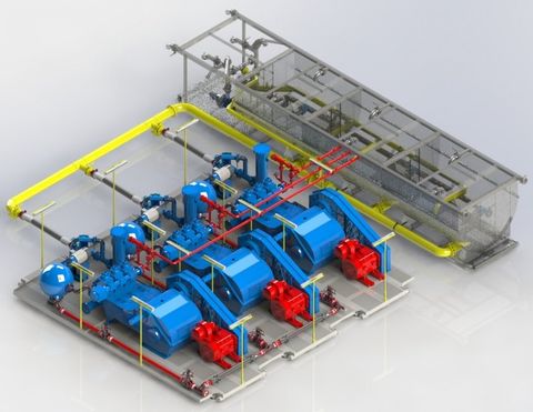
This multistage system utilizes several of Sigma’s advanced products that are proven to maximize efficiencies and upgrade operations of any reciprocating pumping system by themselves.
The Charge Free Dampening System™ is categorically the most sophisticated pulsation control available for your rigs’ pumping operations. With the introduction of the CFD System, Sigma Drilling Technologies proves to be the authority on state-of-the-art advancements in pulsation control technologies.

Mud pump is one of the most critical equipment on the rig; therefore personnel on the rig must have good understanding about it. We’ve tried to find the good training about it but it is very difficult to find until we’ve seen this VDO training and it is a fantastic VDO training about the basic of mud pumps used in the oilfield. Total length of this VDO is about thirteen minutes and it is worth to watch it. You will learn about it so quickly. Additionally, we also add the full detailed transcripts which will acceleate the learning curve of learners.
Powerful mud pumps pick up mud from the suction tank and circulate the mud down hole, out the bit and back to the surface. Although rigs usually have two mud pumps and sometimes three or four, normally they use only one at a time. The others are mainly used as backup just in case one fails. Sometimes however the rig crew may compound the pumps, that is, they may use three or four pumps at the same time to move large volumes of mud when required.
Rigs use one of two types of mud pumps, Triplex pumps or Duplex pumps. Triplex pumps have three pistons that move back-and-forth in liners. Duplex pumps have two pistons move back and forth in liners.
Triplex pumps have many advantages they weight 30% less than a duplex of equal horsepower or kilowatts. The lighter weight parts are easier to handle and therefore easier to maintain. The other advantages include;
• One of the more important advantages of triplex over duplex pumps, is that they can move large volumes of mud at the higher pressure is required for modern deep hole drilling.
Triplex pumps are gradually phasing out duplex units. In a triplex pump, the pistons discharge mud only when they move forward in the liner. Then, when they moved back they draw in mud on the same side of the piston. Because of this, they are also called “single acting.” Single acting triplex pumps, pump mud at a relatively high speeds. Input horsepower ranges from 220 to 2200 or 164 to 1641 kW. Large pumps can pump over 1100 gallons per minute, over 4000 L per minute. Some big pumps have a maximum rated pressure of over 7000 psi over 50,000 kPa with 5 inch/127 mm liners.
Here is a schematic of a triplex pump. It has three pistons each moving in its own liner. It also has three intake valves and three discharge valves. It also has a pulsation dampener in the discharge line.
Look at the piston at left, it has just completed pushing mud out of the liner through the open discharge valve. The piston is at its maximum point of forward travel. The other two pistons are at other positions in their travel and are also pumping mud. But for now, concentrate on the left one to understand how the pump works. The left piston has completed its backstroke drawing in mud through the open intake valve. As the piston moved back it instead of the intake valve off its seat and drew mud in. A strong spring holds the discharge above closed. The left piston has moved forward pushing mud through the now open discharge valve. A strong spring holds the intake valve closed. They left piston has completed its forward stroke they form the length of the liner completely discharging the mud from it. All three pistons work together to keep a continuous flow of mud coming into and out of the pump.
Crewmembers can change the liners and pistons. Not only can they replace worn out ones, they can also install different sizes. Generally they use large liners and pistons when the pump needs to move large volumes of mud at relatively low pressure. They use a small liners and pistons when the pump needs to move smaller volumes of mud at a relatively high pressure.
In a duplex pump, pistons discharge mud on one side of the piston and at the same time, take in mud on the other side. Notice the top piston and the liner. As the piston moves forward, it discharges mud on one side as it draws in mud on the other then as it moves back, it discharges mud on the other side and draws in mud on the side it at had earlier discharge it. Duplex pumps are therefore double acting.
Double acting pumps move more mud on a single stroke than a triplex. However, because of they are double acting they have a seal around the piston rod. This seal keeps them from moving as fast as a triplex. Input horsepower ranges from 190 to 1790 hp or from 142 to 1335 kW. The largest pumps maximum rated working pressure is about 5000 psi, almost 35,000 kPa with 6 inch/152 mm linings.
A mud pump has a fluid end, our end and intake and the discharge valves. The fluid end of the pump contains the pistons with liners which take in or discharge the fluid or mud. The pump pistons draw in mud through the intake valves and push mud out through the discharge valves.
The power end houses the large crankshaft and gear assembly that moves the piston assemblies on the fluid end. Pumps are powered by a pump motor. Large modern diesel/electric rigs use powerful electric motors to drive the pump. Mechanical rigs use chain drives or power bands (belts) from the rig’s engines and compounds to drive the pump.
A pulsation dampener connected to the pump’s discharge line smooths out surges created by the pistons as they discharge mud. This is a standard bladder type dampener. The bladder and the dampener body, separates pressurized nitrogen gas above from mud below. The bladder is made from synthetic rubber and is flexible. When mud discharge pressure presses against the bottom of the bladder, nitrogen pressure above the bladder resists it. This resistance smoothes out the surges of mud leaving the pump.
Here is the latest type of pulsation dampener, it does not have a bladder. It is a sphere about 4 feet or 1.2 m in diameter. It is built into the mud pump’s discharge line. The large chamber is form of mud. It has no moving parts so it does not need maintenance. The mud in the large volume sphere, absorbs this surges of mud leaving the pump.
A suction dampener smooths out the flow of mud entering into the pump. Crewmembers mount it on the triplex mud pump’s suction line. Inside the steel chamber is a air charged rubber bladder or diaphragm. The crew charges of the bladder about 10 to 15 psi/50 to 100 kPa. The suction dampener absorbs surges in the mud pump’s suction line caused by the fast-moving pump pistons. The pistons, constantly starts and stops the mud’s flow through the pump. At the other end of the charging line a suction pumps sends a smooth flow of mud to the pump’s intake. When the smooth flow meets the surging flow, the impact is absorbed by the dampener.
Workers always install a discharge pressure relief valve. They install it on the pump’s discharge side in or near the discharge line. If for some reason too much pressure builds up in the discharge line, perhaps the drill bit or annulus gets plugged, the relief valve opens. That opened above protects the mud pump and system damage from over pressure.
Some rig owners install a suction line relief valve. They install it on top of the suction line near the suction dampener. They mount it on top so that it won’t clog up with mud when the system is shut down. A suction relief valve protects the charging pump and the suction line dampener. A suction relief valve usually has a 2 inch or 50 mm seat opening. The installer normally adjusts it to 70 psi or 500 kPa relieving pressure. If both the suction and the discharged valves failed on the same side of the pump, high back flow or a pressure surge would occur. The high backflow could damage the charging pump or the suction line dampener. The discharge line is a high-pressure line through which the pump moves mud. From the discharge line, the mud goes through the stand pipe and rotary hose to the drill string equipment.
New W-440 ( IMPORT ) SINGLE-ACTING TRIPLEX MUD PUMP RATED INPUT POWER 324 KW (440 HP) RATED. STROKE PER MINUTE 320 STROKE/MINUTE(320SPM) STROKE 152.4MM(6″) GEAR RATIO 4.578:1 MAX. WORKING PRESSURE 35 MPA (5000 PSI) VALVE CHAMBER VALVE-OVER API 4# MAX. LINER DIA. 4 1/2″ MAX. LINER MUD PRESSURE(220 STROKE/MINUTE)16.9MPA DIA. OF SUCTION MANIFOLD, 6″ (150#) FLANGE DIA. OF DISCHARGE MANIFOLD 3″(900#)
MAG TRANSMISSION COPELAND / ALLISON 750 AUTOMATIC TRANSMISSION WITH SHIFTER. SKID 8" WIDE X 32" LONG THREE RUNNER (10" WIDE FLANGE BEAM) WITH OILFIELD LOADING HITCHES EACH END, FLOOR PLATED ENTIRE LENGTH OF SKID, CROSS MEMBERS, BUMPER BAR AT ENGINE END OF SKID. SKID SANDBLASTED TO SSPC-6 COMMERCIAL BLAST, PRIMED WITH A ZINC RICH PRIMER AND TOP COATED WITH TWO COATS OF URETHANE IN CUSTOMER CHOICE OF COLOR. DRIVE SHAFT 1710 DRIVE SHAFT WITH U-JOINTS, ADAPTER YOKES AND COMPANION FLANGE AT PUMP DRIVE INPUT. DRIVESHAFT GUARD FROM TRANSMISSION TO PUMP PINION INPUT.
PIPING FROM DISCHARGE OF CENTRIFUGAL PUMP TO SUCTION MANIFOLD OF TRIPLEX PUMP. LINER COOLING PUMP 1" X 1-1/2" CENTRIFUGAL PUMP (1-1/8" SHAFT) DRIVEN BY PINION SHAFT OF PUMP OPPOSITE SIDE THAN POWER INPUT. V-BELT DRIVE . SUCTION PIPING FROM PUMP LINER COOLING TANK AND DISCHARGE PIPING TO TRIPLEX PUMP LINER COOLING MANIFOLD.
7"-10" wide x 30" long x 4" high on a 34" skid. Mud Tank 200 Bbls and trap with 12"gas buster 1/4" crimp wall design two runner skid hinged walkway at sand trap end return trough in sand trap return piping to gas buster and discharge port in trough 4" clean out couplings, access ladders . Primed & painted.

The majority of problems occurring with reciprocating pumps originate on the suction side of the pump. The term “suction” can be misleading due to the fact that single acting pumps do not lift liquid or suck. A better term to use is “the line leading to the inlet manifold on the pump.” Single acting pumps rely upon atmospheric pressure to force the liquid into a low pressure area created by the completed discharge stroke of the piston or a centrifugal pump with sufficient head and flow to deliver liquid to the inlet manifold as needed.
The inlet side of the pump is critical to correct operation. Collapsible hose should never be used on the inlet side and length is always a factor because friction loss will enter the picture. The inlet line should have a large inside diameter, straight and short as possible. This type system yields a huge benefit to the cost of overall maintenance of the pump. The inlet to the pump should be as close to the supply source as possible and sized according to the discharge flow of the pump. Never decrease the inlet manifold diameter of the liquid end in order to use a smaller inlet hose. Always increase the inlet hose by 1 or 2 in. to ensure good inlet conditions for the pump. The inlet velocity should never be less than 1 ft per second or greater than 3 ft per second.
When problems start to occur on the inlet side, those problems can be both visual and audible. The inlet line will start to pulsate. This occurs because of the liquid accelerating and decelerating rapidly. On each rotation of a triplex crankshaft, one inlet valve will be closed and another will be partially open. The third will be fully open on the discharge stroke. This movement of the valves causes the liquid within the supply line to try and stop, start toward the pump and reverse toward the supply all at the same time. Therefore, poorly designed supply lines will show this movement in pulsating form.
This pulsation can also be audible within the pump. You will hear hammering and if severe enough, the discharge line will also began to pulse. If this much cavitation is occurring within the pump, severe damage can and will occur within the power end as well as the liquid end if conditions are not changed. The hammering sound is the audible form of pump cavitation.
Cavitation is caused by insufficient flow or head from the supply tank to the inlet of the pump and the smooth transition from the manifold through the throat of the inlet valve. If the liquid is too viscous or the supply of the liquid is insufficient to meet the required speed (gpm) of the pump, gasses will start to break out of the liquid and form bubbles in the slurry as it passes through the throat of the inlet valve. When the pump is on the discharge stroke and pressure starts to build rapidly from atmosphere to discharge pressure, the bubbles start to implode and cause damage to liquid end components as well as the liquid end itself.
A suction valve or inlet valve is nothing more than an orifice within the system. The suction manifold of the pump should be filled with liquid and moving at a consistent flow rate. As an inlet valve begins to open and liquid flows through, the liquid should be in contact with the face of the piston. This column of liquid should move at the same rate as the piston. If the inlet is inadequate or pump speed too great, gas will break from the liquid in the low pressure zone created by the inlet seat and bubbles will from in the pumping chamber or atmosphere will enter through the liner and piston. Either way, the pumping chamber will not be filled with liquid.
When the discharge stroke begins, the piston is at rest. Half way through the discharge stroke, the piston is traveling at maximum velocity. Ideally, the pumping chamber should be filled with liquid and in contact with the face of the piston. The inlet valve within that chamber should have just closed as the piston starts the discharge stroke. If bubbles have formed, the chamber is only partially filled with liquid. As pressure starts to build within the chamber, the bubbles implode and the piston encounters a partially filled chamber traveling at maximum velocity slamming open the discharge valve and causing a shock wave to be sent throughout the entire system.
If a pump has a satisfactory inlet system, the end user will see the results of that in his hip pocket. If not, he will help support the entire industry with more equipment sales.

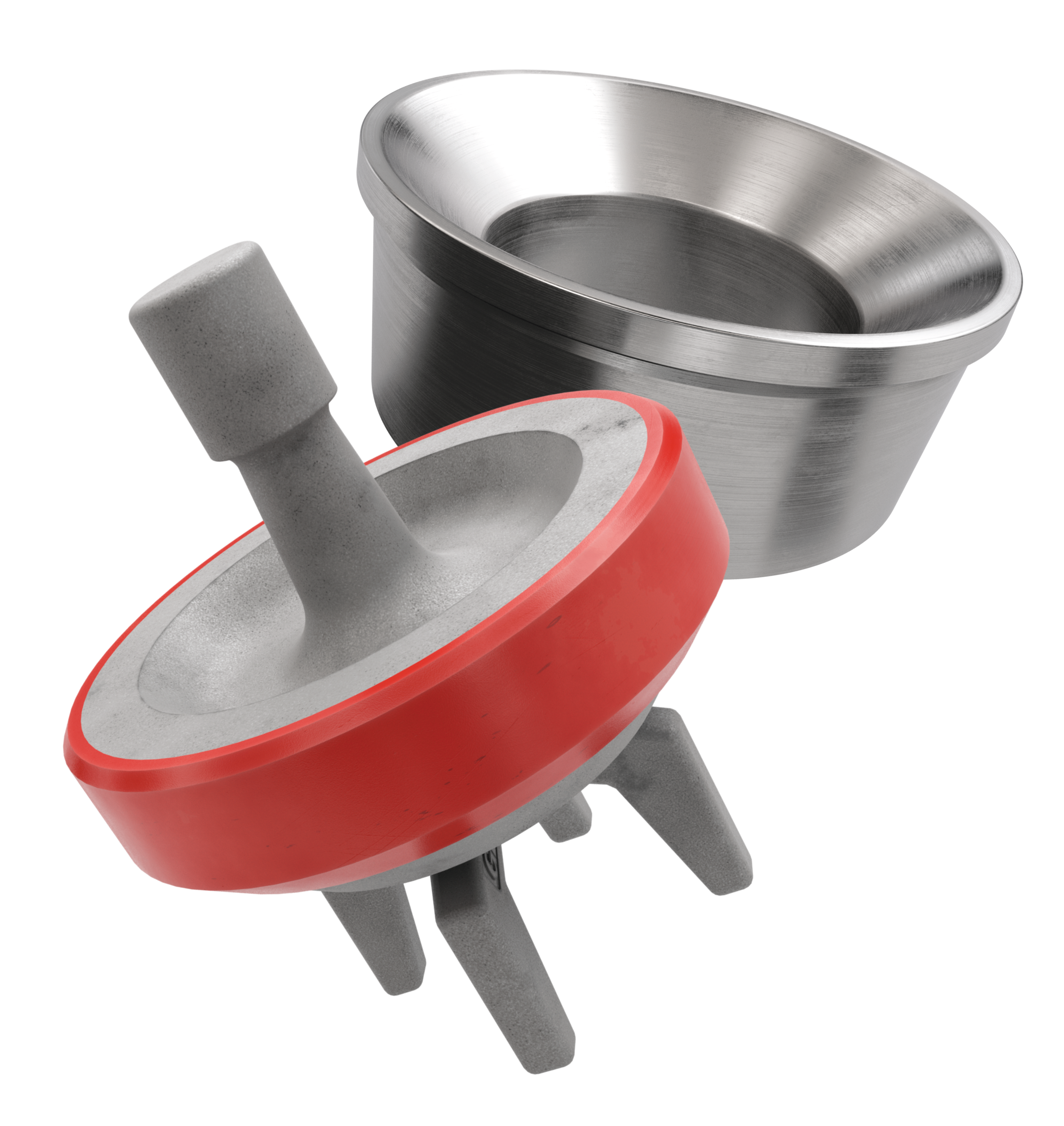
Parker"s HGP Profile delivers over three times the life for suction and discharge seals in multi-plex frac pump applications over traditional HNBR D-rings. Owing to its patent pending geometry and proprietary materials of construction, the HGP Profile can withstand pressure up to 10,000 psi at 3 hertz in abrasive, acidic fracturing fluid.
The policy set forth below outlines the personal data that Power Zone Equipment may collect, how Power Zone Equipment uses and safeguards that data, and with whom we may share it. This policy is intended to provide notice to individuals regarding personal data in an effort to be compliant with the data privacy laws and regulations of the jurisdictions in which Power Zone Equipment operates.
we (or a third party on our behalf) may use personal data to contact you about a Power Zone Equipment offer in support of your business needs or to conduct online surveys to understand better our customers’ needs; and
In addition, certain online technical applications or other interactions you have with Power Zone Equipment may require the entry of business and technical data. By providing the requested information, you are consenting to the processing and storage of such information by Power Zone Equipment. Unless Power Zone Equipment is advised that you want this information removed from Power Zone Equipment’s server, such information may be retained by Power Zone Equipment and used for future commercial communications. A request for removal of this information can be made at the contact information provided below. Power Zone Equipment will take all reasonable precautions to assure that no such information will be provided or divulged to other third parties, except, if applicable, those third parties performing site hosting, maintenance, and related site service activities.

Priming: They don’t have to be primed. They are automatically primed because the fluid they will be pumping is gravity fed directly into the pump, always keeping it primed.
Efficiency: When a pump is submerged there is positive fluid pressure at the inlet of the pump. This condition can increase efficiency due to the less energy required to move fluid through the liquid path of the pump.
Maintenance & Accessibility: When the pump is located outside of the fluid being pumped, the pump can be easily accessible for routine maintenance. A shut-off valve should be positioned before the inlet of the pump which will allow the fluid to the pump to be shut off, then, the pump can be easily removed from the application.
Potential to lose Prime: If the slurry mixture is too thick or viscous, it may not easily feed into the pump which can cause the pump to lose prime. Thus, the mixture needs maintain adequate fluidity to constantly feed the pump and prevent this from happening.
Corrosion: Prolonged exposure to a liquid of any sort will lead to corrosion. Submersible pumps are often used to handle liquids that are corrosive and abrasive. Seals are especially prone to corrosion, which leads to leaks and damage to the motor. To counteract corrosion these pumps need to be made of corrosion-resistant material, which can make them more expensive than other types of pumps of the same capacity.
Wherever possible, flooded suction pumps should be inspected as often as possible. In this way, any necessary repairs can then be carried out to prolong the life of the pump.


 8613371530291