
hawkjaw power tong price

-Select-AfghanistanAlbaniaAlgeriaAmerican SamoaAndorraAngolaAnguillaAntigua and BarbudaArgentinaArmeniaArubaAustraliaAustriaAzerbaijan RepublicBahamasBahrainBangladeshBarbadosBelarusBelgiumBelizeBeninBermudaBhutanBoliviaBosnia and HerzegovinaBotswanaBrazilBritish Virgin IslandsBrunei DarussalamBulgariaBurkina FasoBurundiCambodiaCameroonCanadaCape Verde IslandsCayman IslandsCentral African RepublicChadChileChinaColombiaComorosCook IslandsCosta RicaCyprusCzech RepublicCôte d"Ivoire (Ivory Coast)Democratic Republic of the CongoDenmarkDjiboutiDominicaDominican RepublicEcuadorEgyptEl SalvadorEquatorial GuineaEritreaEstoniaEthiopiaFalkland Islands (Islas Malvinas)FijiFinlandFranceFrench GuianaFrench PolynesiaGabon RepublicGambiaGeorgiaGermanyGhanaGibraltarGreeceGreenlandGrenadaGuadeloupeGuamGuatemalaGuernseyGuineaGuinea-BissauGuyanaHaitiHondurasHong KongHungaryIcelandIndiaIndonesiaIraqIrelandIsraelItalyJamaicaJapanJerseyJordanKazakhstanKenyaKiribatiKuwaitKyrgyzstanLaosLatviaLebanonLesothoLiberiaLibyaLiechtensteinLithuaniaLuxembourgMacauMacedoniaMadagascarMalawiMalaysiaMaldivesMaliMaltaMarshall IslandsMartiniqueMauritaniaMauritiusMayotteMexicoMicronesiaMoldovaMonacoMongoliaMontenegroMontserratMoroccoMozambiqueNamibiaNauruNepalNetherlandsNetherlands AntillesNew CaledoniaNew ZealandNicaraguaNigerNigeriaNiueNorwayOmanPakistanPalauPanamaPapua New GuineaParaguayPeruPhilippinesPolandPortugalPuerto RicoQatarRepublic of CroatiaRepublic of the CongoReunionRomaniaRwandaSaint HelenaSaint Kitts-NevisSaint LuciaSaint Pierre and MiquelonSaint Vincent and the GrenadinesSan MarinoSaudi ArabiaSenegalSerbiaSeychellesSierra LeoneSingaporeSlovakiaSloveniaSolomon IslandsSomaliaSouth AfricaSouth KoreaSpainSri LankaSurinameSwazilandSwedenSwitzerlandTaiwanTajikistanTanzaniaThailandTogoTongaTrinidad and TobagoTunisiaTurkeyTurkmenistanTurks and Caicos IslandsTuvaluUgandaUnited Arab EmiratesUnited KingdomUnited StatesUruguayUzbekistanVanuatuVatican City StateVenezuelaVietnamVirgin Islands (U.S.)Wallis and FutunaWestern SaharaWestern SamoaYemenZambiaZimbabwe
Contents Table of Warranty Specification Ordering Sheet Instructions Installation HAWKJAWOPERATION, MAINTENANCE AND
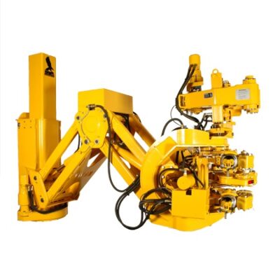
The HawkJaw 65K-950JR is a hanging unit that will spin, make up and break out drill pipe. Itis revolutionary because the tool spins and makes up drill pipe or breaks out and spins drill pipein 12 seconds or less. A patented self-energized grip system provides consistent torque values tothe drill string. Consistent torque ensures that wash outs and "post tightening" down hole do notoccur under normal conditions.
A patented adjustable wrench system eliminates the need for separate jaws, spinning wrench roll-ers or gripping dies. The HawkJaw"s modular design enables the unit to be maintained on the rigfloor.
The HawkJaw 65K-950JR provides a fast, safe and efficient method of spinning and make up orbreak out and spinning. It eliminates costly and dangerous spinning chain and rig tong accidents.
The HawkJaw improves trip time over any comparable torquing and spinning device in the in-dustry. The unit easily adapts to any land or offshore rig because it hangs in the derrick. Han-dles mounted near the control buttons enable one rig hand to move the hanging unit on and offthe pipe.
Contents Table ofOrdering Instructions 8Installation 9 Hanging Cable Location 9 HawkJaw Location 9 Hanging Cable Requirements 10 Hydraulic Requirements 11 Air Requirements 12 Raise/Lower Cylinder Hook - Up 13Operation 14 Start-up Procedure 14 Adjusting the Wrenches 15 Adjust for Make Up 15 Adjusting the Spinner 17 Adjust for Make Up 17 Rest Position 18 Adjust Spinner for Make Up (cont.) 18 Position for Make Up 19 Setting Make Up Torque 21 Make Up 22 Adjusting the Wrenches 23 Adjust for Break Out 23 Adjusting the Spinner 25 Adjust for Break Out 25 Rest Position 26 Adjust Spinner for Break Out (cont.) 26 Position for Break Out 27 Break Out 29 Low Torque Warning Test 30Maintenance & Repair 31 Wrench Maintenance 31 Wrench Hook 32 Wrench Nut 32 Hook Pivot Bearing Cap 32
Table of Contents 3 Table of Contents (cont.) Wrench Maintenance 32 Grip Cylinder Pivot Points 33 Torque Cylinder Pivot Points 33 Wrench Maintenance 33 Mounting Arm Pivot Points 34 Hydraulic Filter 35 Hydraulic Filter Maintenance 35 Air Filter 36 Changing the Hook Dies 37 Changing the Heel Dies 38 Spinner Maintenance 40 Chain Lubrication 40 Drive Roller Sprocket Bearings 41 Spinner Grip Cylinders 42 Chain Drive Shaft Bearing 42 Spinner Mount Sliding Tube 43 Reducer Gear Box 43 Changing the Spinner Chain 44 Chain 44 Drive Rollers 46 Changing the Drive Roller Sprocket Bearings 48 Changing the Torque Cylinder 50 Changing the Grip Cylinders 55 Top Grip Cylinder 55 Middle Grip Cylinder 57 Bottom Grip Cylinder 61 Removing Linkage Bolts 63Trouble Shooting 65Drawings 7065K-950JR Full Hawkjaw Jr Assembly 7065K-950JR Middle Wrench Assembly 7265K-950JR Top-Bottom Wrench Assembly 7465K-950JR Spinner Assembly 7665K-950JR Stand Assembly 7865K-950JR Main Manifold Assembly 8065K-950JR Hydraulic Connections 8265K-950JR Main Manifold Air Connections 8465K-950JR Panel, Left Control Handle Assembly 8665K-950JR Panel, Right Control Handle Assembly 88
Your Hawkjaw must be free of material and workmanship defects for a period of six months fromthe date of delivery. If any items fail because of a manufacturing defect within that period of time,that item will be replaced by Hawk Industries. Hawk Industries at its discretion may extend thiswarranty period.
Factory specifications for hydraulics, pneumatics, lubricants, adjustments and safety precautionsas set forth in the operation and maintenance manual are for the mutual protection of the owner ofthe HawkJaw 65K-2GJR and the company. Failure to adhere to these specifications can reduce theefficiency or life of the equipment and/or cause bodily injury.
WarningThe Hawkjaw includes specially modified valves, fasteners and other components for extremeenvironments and service. Any attempt to substitute standard components could reduce reliabil-ity and performance, void the warranty and/or cause bodily injury. Any modification made byany third party without express written consent of Hawk Industries Inc. shall nullify the existingstanding warranty.
AIR POWER SOURCE: 100 psi @ 2-10 cfmHYDRAULIC POWER SOURCE: 2,500 psi @ 20-35 gpmHYDRAULIC POWER SOURCE TYPE: Closed Center System standard, Open Center System optional
Hanging Cable Location1. Anchor the hanging cable to a point as close to the derrick crown as possible. The longer the hanging cable, the easier the HawkJaw is to move on and off the drill pipe.2. Locate the cable hang point as high above the center of the rotary table as possible. The cable must hang within 2"-4" ft. of the rotary table center.
The hanging cable must permit the HawkJaw to move from the drill pipe connection to themouse hole connection to the HawkJaw rest position (3"- 5" away from the rotary table).
Installation1. Place the HawkJaw on the side of the rotary table away from the setback zone. This allows the drill pipe stands to swing straight from pick-up to stabbing.2. If possible, place the HawkJaw on the opposite side of the setback zone. If the rig has dual setback zones, Step 1 applies.3. The HawkJaw may rest on the rig floor 3" -5" ft. away from the rotary table.
Installation 9 Hanging Cable Requirements1. 5/8" diameter steel cable.2. Appropriate hanging cable hardware for 5/8" diameter steel cable.3. Enough cable length to suspend the Hanger Eye (HE) 20" ft. above the rig floor.4. Enough cable length to allow the HawkJaw to rest on the rig floor 3"- 5" ft. away from the rotary table with the lift cylinder completely stroked out. The lift cylinder is 13" ft. long when completely stroked out.
10 Installation Hydraulic Requirements1. Pressure compensated pump set to pressure compensate at 2600 psi.2. Minimum volume of 20 gpm. 35 gpm for top performance.3. 1" minimum Pressure line. 1 1/4" Pressure line if the power unit is located more than 100" apart from the HawkJaw. The hose working pressure must be 3000 psi or greater.4. 1 1/4" minimum Tank line. 500 psi minimum hose working pressure.5. Hawk approved pressure side non-collapsible on-board 3000 psi filter (HF) (Part # 061- H25). Initial filter element supplied with the HawkJaw.6. Hawk approved quick disconnects (Part # 061-H26). Initial quick disconnects supplied with the HawkJaw.7. Hydraulic power unit located in a clean, dry, ventilated area.8. Enough slack in the lines for the HawkJaw to move from its rest position to the drill pipe connection to the mouse hole connection.
The HawkJaw is a closed center system The HawkJaw must receive cleanwhich must have a pressure compensated hydraulic fluid. Running thevolume controlled power unit. If the only HawkJaw without a Hawk approvedavailable hydraulic power unit is constant pressure-side filter (Part # 061-H25)
Installationvolume, then the optional hydraulic con- voids the warranty and severelyverter kit (Part # 061-J80) is required. shortens component life.Running the HawkJaw with a constantvolume hydraulic power unit may result inbodily injury and will cause damage to theHawkJaw and to the hydraulic power unit.
Installation 11 Air Requirements1. Clean, dry air at 100 psi @ a negligible volume.2. On board auto-dump air filter (AF) (part# 061-A22), located on board the rear of the Hawkjaw.3. Enough slack in the line for the HawkJaw to move from its rest position to the drill pipe
The HawkJaw must receive clean, dry air. Running the HawkJaw without a Hawk ap- proved air filter (AF) voids the warranty and shortens component life.
12 Installation Raise/Lower Cylinder Hook - Up1. Use the Raise/Lower cylinder Cap side Bolt (B) to connect the HawkJaw Suspension Ring (SR) to the Raise/Lower cylinder (C).2. Use the Raise/Lower cylinder Cap side Lock Nut (N) to secure the Raise/Lower cylinder Cap side Bolt (B).3. Connect the Hanger Eye (HE) to the hanging cable.4. Connect the HawkJaw Rod side (HR) and Cap side (HC) hydraulic Leader hoses to the Raise/Lower cylinder Rod side (RR) and Cap side (RC) hoses. NOTE NOTE Tightly connect the hose fittings. A loose Make sure the rod side of the Raise/ hose connection causes a pressure drop in Lower cylinder (R) connects to the the hydraulic fluid which heats up the fluid hanging cable. and reduces component life. HE Part Numbers Part Name Part # Male Quick Disconnect (HR, RC) 061-H26M R Female Quick Disconnect (HC, RR) 061-H26F
Installation 13 Start-up Procedure1. Connect the air power source with the Air (A) line.2. Make sure the hydraulic reservoir is full.3. Connect the hydraulic Pressure (P), Tank (T) and Air (A) lines. "P" and "T" Port Designations are stamped on the Main Hydraulic Manifold (M). Do not hook up the hoses backward
16 Operation Position for Make Up SR LTS1. Stab the drill stand.2. Center the Suspension Ring (SR) on the Lateral tilt screw (LTS).3. If the HawkJaw rests on the rig floor, use Raise (R) to raise the HawkJaw 1"- 2" ft. off the rig floor.4. If the HawkJaw is hooked back to the CH derrick, unhook the HawkJaw.5. Use the Control Handles (CH) to pull the HawkJaw onto the drill pipe con- nection.6. Use Raise (R) and Lower (L) to cen- ter the Top wrench dies (TD) and the Middle wrench dies (MD) between the shoulder (S).7. Keep the Middle wrench dies (MD) away from the Hard banding (HB).8. Keep the Top wrench dies (TD) and the Middle wrench dies (MD) away from
HB MD Operation 19 Position for Make Up (cont.) TW 9. Check that the HawkJaw Top wrench (TW), Middle wrench (MW) and Bottom wrench (BW) hang straight and level when the drill pipe is against the pipestop.10. If the HawkJaw wrenches (TW, MW, BW) hang tilted forward or backward adjust using theTILT cylinder. Place the MAKE/BREAK (MB) selector in the center. Use the RAISE button to TILT back and the LOWER button to TILT forward. 11. If the HawkJaw wrenches (TW, MB MW PS BW MW,BW) hang sloped to the right or left, use the Control Handles (CH) to back the HawkJaw off the pipe. Return the MAKE/BREAK selector to MAKE and use the LOWER button to lower the HawkJaw to the rig floor. Repeat Step 2.12. Make sure the Pipe Stop (PS) is against the drill pipe connec- tion.
The HawkJaw performs best when it TILT forward TILT backhangs aligned with pipe. (LOWER button) (RAISE button)
TILT Cylinder20 Operation Setting Make Up Torque RN RNA TN Warning When Hawkjaw is at rest, press in the red E-Stop (E) button.1. Follow the steps on pages 14-21.2. Use the Red needle adjust (RNA) to rotate the Torque gauge red needle (RN) to the desired torque.3. Rotate the Torque Set knob (K) counter- clockwise as far as the Torque Set knob (K) will turn.4. Rotate the Selector Switch (SS) Shown set for 30,000 ft. lbs. to the make position. SS G GH5. Press in the Grip Hold (GH) but- ton.6. Press and hold Spin (S) until the stand rotates down to the shoulder.7. Release Spin (S).8. Push in and hold the wrench Grip (G).9. Press and hold Torque (T). While holding down Torque (T),
Operation rotate the Torque Set knob (K) clockwise.10. When the Torque gauge needle (TN) reaches the desired torque, stop rotating the Torque Set knob (K).11. Release Torque (T). Immediately release the wrench Grip (G).12. Pull out the Grip Hold (GH) but- ton.13. The Hawkjaw torque is now set and can now be removed from the pipe.
S T K Operation 21 Make Up1. Follow the steps on pages 14-21. RN TN2. Press in the Grip Hold (GH) but- ton.3. Press and hold Spin (S) until the stand rotates down to the shoulder.4. Release Spin (S).5. Push in and hold the wrench Grip (G).6. Push and hold down Torque (T).7. Watch the Torque gauge needle (TN).8. When the Torque gauge needle Shown set for 30,000 ft. lbs. rises above and settles at the G GH desired torque (this rising above is a normal hydraulic adjustment), release Torque (T). Immediately release Torque (T) button and the wrench Grip (G) button.8a. Note: If the desired torque is not achieved, repeat steps 5-8.9. Pull out the Grip Hold (GH) but- ton.10. The Hawkjaw can now be re-
24 OperationOperation Position for Break Out SR LTS1. Stab the drill stand.2. Center the Suspension Ring (SR) on the Lateral tilt screw (LTS).3. If the HawkJaw rests on the rig floor, use Raise (R) to raise the HawkJaw 1"- 2" ft. off the rig floor.4. If the HawkJaw is hooked back to the derrick, unhook the HawkJaw.5. Use the Control Handles (CH) to pull CH the HawkJaw onto the drill pipe con- nection.6. Use Raise (R) and Lower (L) to center the Middle wrench dies (MD) and the Bottom wrench dies (BD) between the shoulder (S).7. Keep the Bottom wrench dies (BD) away from the Hard banding (HB).8. Keep the Middle wrench dies (MD) and the Bottom wrench dies (BD) away
HB BD Operation 27 Position for Break Out (cont.) TW 9. Check that the HawkJaw Top wrench (TW), Middle wrench (MW) and Bottom wrench (BW) hang straight and level when the drill pipe is against the pipestop.10. If the HawkJaw wrenches (TW, MW, BW) hang tilted forward or backward adjust using the TILT cylinder. Place the MAKE/BREAK (MB)selector in the center. Use the RAISE button to TILT back and the LOWER button to TILT forward. 11. If the HawkJaw wrenches (TW, MW,BW) hang sloped to the MW PS BW right or left, use the Control MB Handles (CH) to back the HawkJaw off the pipe. Return the MAKE/BREAK selector to BREAK and use the LOWER button to lower the HawkJaw to the rig floor. Repeat Step 2.12. Make sure the Pipe Stop (PS) is against the drill pipe connection.
The HawkJaw performs best when it TILT forward TILT backhangs aligned with pipe. (LOWER button) (RAISE button)
28 Operation TILT Cylinder Break Out SS GH1. Follow the steps on pages 14, 24- 30.2. Rotate the Selector Switch (SS) clockwise to the break position.3. Push in the Grip Hold (GH) but- ton. G4. Push and hold in the wrench Grip (G).5. Push and hold down Torque (T).6. When break out occurs, release Torque (T). Immediately re- lease the wrench Grip (G). See note below.7. Press and hold down Spin (S) S T until the stand pops out of the connection. Release Spin (S). If the stand will not spin, release Spin (S). Repeat Steps 4-6.8. Pull out the Grip Hold (GH) but- ton.9. You are now able to remove the Hawkjaw from the pipe.
Test#1: Hawk strongly recom-mends testing the Low TorqueWarning System on every trip.If this test procedure is not per- E SS GHformed, the drill string could beover torqued. Disconnect the Lowtorque warning test connector (LTC)located as shown. Torque the firstconnection. Note the torque gageneedle position; keep the Hawkjawpositioned on the same connection. GNow re-connect the Low TorqueWarning Connector. Re-torquethe connection. The torque gageshould indicate the same reading.If it does not, see Trouble Shooting
Test#2:Hawk strongly recommendstesting the Low Torque WarningSystem on every trip. If this testprocedure is not performed, the drillstring could be under torqued.When breaking the first connec-tion, push in the Grip Hold (GH) NOTEbutton, hold down both Torque (T) For safety, push in the "E"and Grip (G) until the Torque Cyl- stop when the HawkJaw is atinder fully strokes out. When the rest.Torque Cylinder fully strokes out,the Torque Gauge Needle will fall LTC WARNINGoff to approximately an 8000 Ft.- Lb Do not make up pipe with the low torque warning test connectorreading. If this does not occur, see dis-connected. This may result inTroubleshooting p. 96. under torqued pipe in the hole.
1. Make sure the HawkJaw is off the drill pipe connection and in the rest position on the derrick.2. Shut down the Hydraulic power unit.3. Press, push, and pull all control buttons repeatedly to bleed D5 D3 D4 D6 hydraulic pressure.4. Disconnect the Air power sup- ply.5. Press, push, and pull all control buttons repeatedly to bleed air pressure.6. Assume that there is still a load on every actuator. Proceed with
1. Make sure the HawkJaw is off the drill pipe connection and in the rest position on the derrick.2. Shut down the Hydraulic power unit.3. Press, push, and pull all control buttons repeatedly to bleed hydraulic pressure. G5 G64. Press the E-Stop button on the right control handle.5. Press the E-Stop button on the right control handle.6. Assume that there is still a load on every actuator. Proceed with caution.
1. Make sure the HawkJaw is off the drill pipe connection and in the rest position on the derrick.2. Shut down the Hydraulic power unit.3. Press, push, and pull all control MP3 MP4 buttons repeatedly to bleed hydraulic pressure.4. Press the E-Stop (E) button on the right control handle.5. Disconnect the Air power sup- ply.6. Assume that there is still a load on every actuator. Proceed with
34 Maintenance & Repair Hydraulic Filter Maintenance Change Every 2 Months RB Initial Steps SC1. Depress the Red button (RB) located under the See-through rubber weather cap (SC). S2. Operate the HawkJaw.3. If the Red button pops up, proceed with Step 4.4. Make sure the HawkJaw is off C FE the drill pipe connection and in the rest position on the derrick.5. Shut down the Hydraulic power unit.6. Press, push, and pull all control buttons repeatedly to bleed hydraulic pressure.7. Press the E-Stop (E) button on the right control handle.8. Disconnect the Air power sup- ply.9. Assume that there is still Part Numbers pressure in the Pressure Line. Part Name Part #
Maintenance & Repair Filter Cannister/Body (C) 061-H25B Hydraulic Filter Weather Cap (RB) 061-H25C Filter Seal Kit (S) 061-H25SK1. Remove the Canister (C).2. Remove the Filter Element (FE). WARNING NOTE3. Insert the new Filter Element.4. Replace the Filter Canister (C). Running the HawkJaw If the Canister without a Hawk approved (C) leaks, change pressure-side filter (Part # the "O" ring and 061-H25) voids the war- back-up (S). ranty and severely short- ens component life.
Initial Steps CB1. Disconnect the Air power sup- ply. FC
WARNING Running the HawkJaw without a Hawk approved air filter (Part # 061-J29 & 061-A22) voids the warranty and shortens component life. In-Line Filter Part Numbers On-Board Filter Part Numbers
1. Make sure the HawkJaw is off the drill pipe connection and in the rest position on the derrick.2. Shut down the Hydraulic power unit.3. Press, push, and pull all con- trol buttons repeatedly to bleed hydraulic pressure.4. Press the E-Stop (E) button on the right control handle. D5. Disconnect the Air power supply.6. Assume that there is still a load on every actuator. Proceed with
1. Make sure the HawkJaw is off the drill pipe connection and in the rest position on the derrick.2. Shut down the Hydraulic power unit.3. Press, push, and pull all con- trol buttons repeatedly to bleed hydraulic pressure.4. Press the E-Stop (E) button on the right control handle.5. Disconnect the Air power D DH supply.6. Assume that there is still a load on every actuator. Proceed with P
Chain Lubrication S CO1. Pull the Hawkjaw onto the pipe.2. Press in the Grip Hold (GH) but- ton.3. Press and hold the Spin (S) button. While holding down the Spin (S) button, press and hold the Chain Oiler (CO) button for 3 seconds.4. Release the Spin (S) button.5. Pull out the Grip Hold (GH) but- ton.
CAUTION: This chain oiling system uses minimal amount of hydraulic oil from power unit - we sug- gest you monitor hydraulic oil level accordingly.
1. Make sure the HawkJaw is off the drill pipe connection and in the rest position on the derrick.2. Shut down the Hydraulic power unit.3. Press, push, and pull all con- trol buttons repeatedly to bleed hydraulic pressure.4. Press the E-Stop (E) button on the right control handle.5. Disconnect the Air power G3 BC G4 supply.6. Assume that there is still a load on every actuator. Proceed with
Maintenance & Repair 43 Changing the Spinner ChainTools Required7/16" wrench, Hammer, Needle-Nose Pliers Initial Steps1. Make sure the HawkJaw is off the drill pipe connection and in the rest position on the derrick.2. Shut down the Hydraulic power unit.3. Press, push, and pull all con- trol buttons repeatedly to bleed hydraulic pressure. SD QR4. Press the E-Stop (E) button on the right control handle.5. Disconnect the Air power supply.6. Assume that there is still a load on every actuator. Proceed with
1. Make sure the HawkJaw is off the drill pipe connection and in the rest position on the derrick.2. Shut down the Hydraulic power unit.3. Press, push, and pull all con- trol buttons repeatedly to bleed hydraulic pressure.4. Press the E-Stop (E) button on the right control handle.5. Disconnect the Air power supply. Drive Rollers6. Assume that there is still a load on every actuator. Proceed with
1. Make sure the HawkJaw is off the drill pipe connection and in the rest position on the derrick.2. Shut down the Hydraulic power unit.3. Press, push, and pull all con- trol buttons repeatedly to bleed (9) & (12) X 20 hydraulic pressure.4. Press the E-Stop (E) button on (10) the right control handle.5. Disconnect the Air power supply.6. Assume that there is still a load on every actuator. Proceed with
Initial Steps1. Make sure the HawkJaw is off the drill pipe connection and in the rest position on the derrick.2. Shut down the Hydraulic power unit.3. Press, push, and pull all control buttons repeatedly to bleed hydraulic pressure.4. Press the E-Stop (E) button on the right control handle. CH RH BCP BC5. Disconnect the Air power supply.6. Assume that there is still a load on every actuator. Proceed with
1. Make sure the HawkJaw is off the drill pipe connection and in the rest position on the derrick.2. Shut down the Hydraulic power unit.3. Press, push, and pull all control buttons repeatedly to bleed hydraulic pressure.4. Disconnect the Air power sup- ply.5. Press, push, and pull all control buttons repeatedly to bleed air CH RH pressure.6. Assume that there is still a load on every actuator. Proceed with
1. Make sure the HawkJaw is off the drill pipe connection and in the rest position on the derrick.2. Shut down the Hydraulic power unit.3. Press, push, and pull all control buttons repeatedly to bleed hydraulic pressure.4. Disconnect the Air power supply.5. Assume that there is still a load on every actuator. Proceed with MW caution.
1. Make sure the HawkJaw is off the drill pipe connection and in the rest position on the derrick.2. Shut down the Hydraulic power unit.3. Press, push, and pull all control buttons repeatedly to bleed CP CH RH RP hydraulic pressure.4. Disconnect the Air power sup- ply.5. Press, push, and pull all control buttons repeatedly to bleed air pressure.6. Assume that there is still a load on every actuator. Proceed with
Hawkjaw performance and The filter element is clogged. Replace the filter ele-speed not up to par. ment. Check the lead-in pressure and tank lines for any
obstructions. Also check the quick disconnects to see that they are securely tightened. A bad quick disconnect can cause the Hawkjaw to malfunction. Replace the faulty connector. The air pressure is low. Increase the air pressure
draulic pressure. Do not increase the pressure over 2600 psi, or the hydraulic fluid will pass over the relief valve and heat up the hydraulic fluid. This will cause damage to the HawkJaw and to the pump, and will severely shorten component life. Check to make sure the hydraulic power unit is
Hawkjaw. Feel the outside of all actuators. If a por- tion of the cylinder surface is too hot to leave your hand on the cylinder, the leak is inside the cylinder. Replace the cylinder seals. If necessary, replace the cylinder.
Continued on next page.66 Troubleshooting Trouble ShootingSymptom RemedyWhile torquing pipe, a desired The Hawkjaw may have an obstructed tank lead-torque setting cannot be achieved in hose or quick disconnect. Clear the tank lineor the torque control valve will obstruction and or tighten or replace tank line quicknot effect the torque output of disconnect.the Hawkjaw. Make sure the Low Torque Warning System pres-
is at 2600 psi. If the pump pressure compensator set- ting is above the pressure relief valve setting on the HawkJaw or the pressure relief valve setting on the hydraulic power unit, the hydraulic fluid will heat up rapidly. There is a leak in the hydraulic system.
is at 2600 psi. If the pump pressure compensator set- ting is above the pressure relief valve setting on the HawkJaw or the pressure relief valve setting on the hydraulic power unit, the hydraulic fluid will heat up rapidly. There is a leak in the hydraulic system.
the pump pressure compensator setting is at 2600 psi on a known, tested hydraulic power unit, and the hydraulic power unit pressure relief valve is set above the pump pressure compensator setting and the hydraulic fluid still heats up, then the pres- sure relief valve setting on the HawkJaw has been changed. The pressure relief valve adjustment is set at Hawk Industries. Under no circumstances should this pressure relief valve be adjusted. Adjusting the pressure relief valve setting voids the warranty and can cause severe damage to the HawkJaw and the hydraulic power unit and shorten component life. Shooting Trouble
However, if this valve has been adjusted below 2600 psi, and the pressure compensator setting is at 2600 psi, the hydraulic fluid will pass over the pressure relief valve. This will heat up the hydraulic fluid rapidly. Properly set the pressure relief valve ad- justment. On a known, tested hydraulic power unit, Continued on next page.
down the hydraulic power unit. Push in and pull out all Grip buttons repeatedly to bleed all hydraulic pressure. Pull out all Grip buttons. Disconnect the air supply hose to the HawkJaw. Disconnect the Raise/Lower cylinder Hanger Eye from the hanging cable. Place the Raise/Lower cylinder Rod side end on the rig floor. Connect the air supply hose to the HawkJaw. Turn on the hydraulic power unit. Push in the Lower button, and hold down the Lower button. While holding down the Lower button, check for Raise/Lower cylinder piston seal integrity. Make sure no bodily parts are in the extension path of the cylinder rod. Slowly loosen the HawkJaw Rod side Leader hose. Check for fluid flow. If there is a piston seal leak, fluid will flow with volume out of the Rod side leader hose. Replace the seals. Replace the cylinder if necessary. Push in the Raise but- ton, and hold down the Raise button. While hold- ing down the Raise button, check for Raise/Lower cylinder piston seals integrity. Make sure no bodily parts are in the extension path of the cylinder rod. Continued on next page.
68 Troubleshooting Trouble ShootingSymptom RemedyThe Raise/Lower Cylinder Slowly loosen the HawkJaw Cap side Leader hose.moves at an undesirerable Check for fluid flow. If there is a piston seal leak,speed. (cont.) fluid will flow with volume out of the Cap side leader hose. Replace the seals.


 8613371530291