
hawkjaw power tong pricelist

Texas International Oilfield Tools, LTD. realizes Power Tongs and their accessories are the key to our success. We are the world"s largest stocking supplier of McCoy Global Power Tongs. McCoy focuses on providing the highestquality drilling and completion equipment, customized to your needs, as cost-efficiently as possible. McCoy manufactures and distributes high-performance tubular equipment for the oil and gas industry, suited to both workover and drilling applications on land-based and offshore rigs. As your one-stop shop for energy products and services, we also provide specialized hydraulic power tongs, dies and inserts, make/break torque equipment, and computerized torque turn management systems.
Notice of Change from McCoy: Our KT7585 model is being rebadged as KT8625. There have been no design changes to this tong, it still functions the same and has the same torque and RPM. Our KT8625 model is being rebadged as HD8625. There have been no design changes to this tong, it still functions the same and has the same torque and RPM. Texas International Oilfield Tools, LTD has expanded to give you better service featuring modern manufacturing, assembly, hydraulic and quality areas, an extensive warehouse, and office space. The new facility features a 5,000 square foot showroom. Texas International Oilfield Tools, LTD manufactures hard-to-find oilfield tools. Our experience and knowledge is unsurpassed in Oilfield Drilling and Casing Tools. In our 15 years plus of experience we have thrived for quality, excellence and your satisfaction. We are located in the hub of the oilfield industry in Houston, Texas; close to the airport, shipping yards and freight companies. More...
LAND DRILLING UNITINDEX-DRILLING EQUIPMENTNo. DESCRIPTION: :HOISTING EQUIPMENT GROUP 5.1 DRAWWORKS 5.2 ROTARY TABLE 5.3 TOP DRIVE SYSTEM 5.4 SWIVEL 5.5 KELLY SPINNER 5.6 KELLY AND KELLY DRIVE BUSHING 5.7 CROWN BLOCK 5.8 TRAVELLING BLOCK 5.9 HOOK DRILL FLOOR EQUIPMENT GROUP 5.10 DRILLING INSTRUMENTATION 5.11 DERRICK 5.12 CASING STABBING BOARD 5.13 TUGGERS AND SHEAVES. MAN-RIDING WINCHES. 5.14 SURVEY LINE PIPE HANDLING EQUIPMENT GROUP 5.15 PIPE SPINNING WRENCH 5.16 EZY-TORQ 5.17 PIPE HANDLING EQUIPMENT 5.18 IRON ROUGHNECK 5.19 PIPE RACKING SYSTEM 5.20 DRILL STRING 5.21 DRILLING SUBS 5.22 FISHING TOOLS 5.23 POWER TONG 5.24 WELL TESTING EQUIPMENT 1 2 3 4 Satisfactory Unsatisfactory Not inspected Not applicable
Check pressure by fitting a pressure gauge to G.P. point. 3 Major Pressure should be 2000 psi 100 psi during operation. 81 Is emergency stop auxiliary brake in easy reach for the Shell DEN 48/90 3 Critical driller. 82 Recommendations to be made regarding the general 4 Minor condition of the system. 83 Recommendations to be made regarding structural 4 Minor improvement to the system. 5.2 ROTARY TABLE Manf: ______Type:______ Horsepower Rating:_______ Static load rating: ____________ Max. opening size: ________ Max. continues rpm:__________ Max. torque rating:____________ 1 Check lube oil pressure and temp. (35 psi, max. temperature 70 C.) 2 Check low lube oil pressure alarm and is it set at 25 psi? 3 Check oil pump drive assembly for wear and misalignment. 4 Check condition of all hoses for aging and damage. 5 Check condition of the drum brake friction surface. 6 Check condition of friction shoe assemblies. (These should be replaced when worn down to 5/32".) 7 Check condition of release springs and torque bars. 8 Check for excessive oil and grease on the drum and shoes. 9 Check condition of the rubber tube. 10 Check the condition of the brake housing for condition and excessive corrosion. 11 Operate rotary brake and check for air leaks. 12 Check all Falk Couplings for play and excessive wear. (Spline type grease filled couplings) 13 Are coupling seals intact. (Seals are often damaged due to incorrect greasing) 14 Check drive coupling guard if seals leak and fasteners are tightened. 15 Check that hold down ring seal, locking wire and retaining band are still in place. 16 Check lube oil for contamination and check magnetic filter. 17 Check for loose parts in gear box / transmission. 18 Check for overall corrosion damage. 19 Check for wear on the gears and couplings / clutches. 20 Check for excessive bearing wear. 21 Run the oil pump and check for plugged oil lines. 22 Check the shifting mechanism of the transmission and shift gears. 23 Check table locking mechanism for proper operation and condition of the springs. 24 Run rotary table at max. speed for half hour. Check for bearing noise, overheating of bearings and vibrations. Hydraulic driven Rotary Table. 25 Check hydraulic drive condition, function check controls. 26 Check for hydraulic oil leaks. 27 Run rotary table on max speed (24 rpm) 28 Check locking system 3 3 3 3 3 3 3 3 3 3 3 3 3 3 3 3 3 3 3 3 3 3 3 3 Major Major Major Minor Major Major Major Major Major Minor Major Major Minor Major Major Minor Major Minor Major Major Major Major Major Major
Recommendations to be made regarding the general condition of the system. 30 Recommendations to be made regarding structural improvement to the system. 5.3 TOP DRIVE DRILLING SYSTEM Manufacturer:________ Type:___________ Drive Motor: Hydraulic/Electric. Electric: Serial/Shunt wound. lamps are in good order. 1 Check that all indicating 2 Check all gauges for proper scale and operation: Torque gauge. (MdaN. and Ft lbs). Make-up torque setting gauge. (MdaN & Ftlbs). RPM speed indicator. Check tool joint breaker to the dolly mountings for tightness. Check compensation cylinders to the bail mountings for tightness. Check drilling motor and brake housing mountings for tightness. Check if the mountings for the derrick loops are mounted far enough from the corner, to insure that the hoses cannot catch under the guide rails, but are far enough back to clear tong lines, tugger lines and stabbing boards. Check the air breather on the exhaust side of the control valves for blockage. Check and ensure that the Link Tilt Intermediate Stops are well secured and springs in good condition. Check that the IBOP crank and roller bracket assembly bolts are safety wired or lock tabs installed. Check if the IBOP actuator shells are replaced by the modified type. Check the upper IBOP valve for any surface damage. (Tong marks) (They should be removed after the valve is madeup). Actuate the IBOP valve. Verify that the stroke adjustment is correct. Mechanically check for complete opening & closing of IBOP. Check the condition of the torque wrench attaching parts, dies, mounting of the reaction arms, etc. Check the hydraulic hoses of the pipe handler and torque wrench for leaks. Check that the torque arrestor & hanger shaft pins are retained with nuts & cotter pins. Check that adequate service loop brackets are made. Check if the cables are properly routed and properly supported in derrick and TDS. Check that the service loops and mud hose are not overstressed or kinked with TDS on stops or at crown. Check the oil level in the gear box with the motor turned off. Check the oil flow indicator for oil going to the lower quill shaft bearing. Check the oil flow to the take-up bearing. [Varco top drives with integrated swivel] (Orifice to be fitted with 500 micron filter). Check the gear box lubricating oil pressure. (The Alsthom Top Drive should have min. 0.5 bar with gearbox running at idle speed).
Check if the lower gear case seals are leaking. Should be greased every day. Inspect the torque wrench stabbing guide for excessive wear and cracks. Check the guide rollers for excessive axial and radial slop and wear. Check series motor overspeed and trip detector. If applicable. Check that the top drive is sufficiently protected against damage by tong lines and tugger cables. Check guide rail for straightness. Check that adequate rail stops are installed. Check that extended swivel bail pins are properly secured. Check if a retrofit dust filter is installed in the closed loop system. Check that the space heaters are wired to be ON whenever the TDS is OFF. Check cooling water flow if applicable. Check if water detection and indication system is operating. (If applicable). Check oil pump loss pressure switch and functioning of indicator system. Check that all grease points are lubricated and pointed out to the crews. Check operating of TDS purge system. Check console purge system. Check automatic shut-down , start interlock and the prepurge period Check transfer panel purge system. Check loss of purge air alarm system and automatic shut down (if provided) Check that the hinge pin of the Varco pipe handler is properly in place. Check that the Split Landing Collar (SLC) retainer is still in place with both halves of the SLC. Check that the six support bolts for the torque wrench are tightened to 1200 Nm and lock wired. (MH Type 1898 and 1899) Check the alarm systems to prevent collision between the Link Tilt Park System and other equipment in the derrick. (Maritime Hydraulic) Check the torque wrench and verify that it follows the makeup and break-out cycles. (15 sec. max. cycle time). Turn on the hydraulic and air power and check for leaks. Actuate link tilt and check operation. Be sure that it operates smoothly and that the elevators reach the mouse hole. Verify that the elevator clears the monkey board when the link tilt is actuated. Check the motor brake for proper operation. (Mud can get into the brake and cause problems). Check the operation of the blower.
When was the weight indicator last calibrated (should be done periodically) Check wear in deadline anchor dies. Check if deadline anchor is well secured and the hold down bolts are tight. Check that the deadline anchor is regular lubricated. Check the condition of the Mud Volume Totalizer system. Check purge air system for leaks and proper regulated pressure. (0.75 psi) Check gain and loss visual and audible warning alarms. Check trip tank level indicator for proper functioning. Check high and low limit alarms of the flow indicator. Check the Geolograph for proper operation. Ensure that the protection cover of the Geolograph line drum is installed. Check that all warning lights are operational. Test low purge air audible alarm system. Test high and low limit alarms. Test pit volume indicators. Check tong torque for leaks and proper torque readings. (Install a calibrated tong gauge on the back up line and check one against the other). Check NDT inspection reports of the deadline anchor.
Check that anchorage"s for the rope or chain are corrosion free and in good order. (They must not be altered with-out Certifying Authority approval.) 24 Check that when a hydraulic unit is in use (cherry picker) the hydraulic system is failsafe in case of loss of hydraulic pressure. 25 Test the hoist and lowering system of the platform. 26 Check that a safety factor of 10:1 is applied to the raising/lowering chain or rope load rating. 27 Are rig specific procedures available for hooking up of the casing stabbing board. 28 Check NDT inspection reports of the high load bearing areas. 29 Recommendations to be made regarding the general condition of the system. 30 Recommendations to be made regarding structural improvement to the system. 5.13 TUGGERS AND SHEAVES Type:__________ Hydraulic/air operated 1 2 3 4 5 6 Check the condition of the drill floor tuggers. (Brake linkage, auto brakes, rims, brake bands, shut of valves, etc). Check that the winch control automatically return to neutral when released. Is the cable end well secured. Check that the brake will hold when load is suspended. Check the cable for crushed, broken or whickered spots. Inspect the tail chain and shackle for stretch, caliper opening in hook, if it is larger then the chain size replace the hook. (Only shackle allowed for Shell operations). Check if air tuggers exhaust is vented to an area that does not create a safety hazard. Check that drum guards are in place and in good condition. Check if protective guards are installed on air line oiler and water separator bowls. Check that the Safe Working Load is clearly marked on each tugger. Check that a ball valve is installed in the main air supply line of each tugger close to the operating control. (This in order to quickly close the air supply in case of a failure of the tugger controls). Check if the tuggers are fitted with a simple spooling device to avoid hand injuries while guiding the wire line. Check the NDT inspection reports that the foundations were inspected. Check the condition of the pedestals and foundations. Check that the winch control automatically return to neutral when released. Check that an auto-brake has been fitted which applies the brake when the control lever is released or on loss of power. Check that the manual operated brake is in good condition. (Must be fitted)
Check operating oil pressure (2000 psi.) If applicable. Check that a back-up pump and motor is installed and hooked up. (Hydraulic units only)? 14 Check the oil reservoir low oil level pump shut off. (Hydraulic units) 15 Function test unit in forward and reverse and verify proper operation. 16 Check that the lifting points are regular NDT inspected. 17 Recommendations to be made regarding the general condition of the system. 18 Recommendations to be made regarding structural improvement to the system. 5.16 EZY-TORQ 1 Check all fasteners for tightness. 2 Check hydraulic system for leaks. 3 Check all hoses for wear and aging. 4 Check condition of the wire line. 5 Check condition of pull back spring. 6 Inspect sheaves, sheave bearings and sheave pins for wear. 7 Check that all mounting points are regularly NDT inspected for cracks. 8 Recommendations to be made regarding the general condition of the system. 9 Recommendations to be made regarding structural improvement to the system. 5.17 PIPE HANDLING EQUIPMENT Manf.:___________ Type:___________ 1 2 Check counter weights and hanging cables for wear and damage. Check if a safety sling is installed to each tong counter weight. Only required when not fully encased or running in guides. Check the clearance between the tong dies and die slots. (Max. 1/16") Check the condition of the "keys" above and below the dies. (Should be the original pins which are locked with a split pin) Visually check the tongs for excessive wear of all jaws, hinges, etc. Check for bent arms and hanging straight. Check the condition of the tong make-up line. Check the condition of the tong break-out line. Check the condition of the tong back-up lines. Check the condition of the tong pull line wire quide rollers.
Inspect the snub-line posts for proper mounting to the drill floor. (Not welded or bolted onto the floor but stabbed through a sleeve/pipe which is affixed to the drill floor as well as to the lower flanges of the main drill floor girders.) Check inserts and insert slots for damage and wear. (Slips to be replaced when there is 1/8 to 3/16" clearance between the back of the inserts and the insert slots). Check condition of the handles. Check for worn hinges and hinge pins. Check with a straight edge the back and face of the slip segments for bent or worn parts. Check that the old style footlatch of the Varco PS-15 power slip assembly has been replaced by a safety latch lock.
Check that the Varco PS-16 air powered slip is fitted with side outlet pressure relief valve. (Setting 250 psi.) Check the condition of the dog collars. Check that the dog collars are stored in a oil bath.
PS-21 and PS-30 Varco slips. 20 Check that the Varco PS-21 or 30 hydraulic powered slip is operating properly. 21 Is the PS-21 or PS-30 modification with the auto grease system (FIF # 889) carried out. 22 Is the PS-21 or PS-30 modification with the Flushing / Filtration kit (FIF#890) system carried out. (free of charge Varco mod.) Is the PS-21 or PS-30 modification with new actuator kit (FIF#891) carried out. (free of charge Varco mod.) Check if insert carriers are properly marked for the size range and the Ram guides for specific pipe size. Are the 13-5/8" _ 14" insets for the PS-30 modified to allow removal and installation of the PS-30 when casing is installed. Check that lifting swivels are of the new style (one piece bail design) a complete removal of the swivel hoist rings and welded brackets is a later modification. Are the inserts for the PS-21 or PS-30 upgraded with load rings as recommended by Varco.
Ensure that all mounted hardware (i.e. bolts, pins etc.) are properly secured with locking wire, lock tabs (bent tab washers) or split pins. Check that all air operated elevators are supplied with load sensors to prevent inadvertent opening when loaded. (Maritime Hydraulic (MH) air-operated elevators can be opened if the elevator is supporting a load less than 2 tons). Check for wear or damage of upsets that would affect elevator efficiency and handling ability or down grade load ratings. Check handles and latches for wear. Function elevators to check for full closing with no slop or wear. Check the correct ID of the DC elevators. (6 " dc: max. ID is 6 1/16", 7 3/4" dc: max. ID is 7 ", 8" dc: max. ID is 7 11/16", 9" dc: max. ID is 8 7/16"). Check that warning labels are fitted to all 3 " and 5" MH-air operated elevators and remote control panels. (Warning of the danger of inadvertent operation while lightly loaded). Check that warning labels are supplied and fitted to VarcoBJ slip type and 18-degree taper air operated elevators. [They can be opened with loads up to 2 tons (1,820 kg). Collar type loads up to 15 tons (13,650 kg)]. Check the integral slips of the 4 1/2" x 2 3/8" dual elevators. (They have been known to fail in service due to improper heat treatment). Check that the BJ 175, 250, 350 and 500 ton elevator/spiders are equipped with a modification kit that has a lock finger instead of a lock cam, which provides a positive lock. Check the hinge pin clearance of the Varco-BJ FMS- 375 elevator. (The hinge pin clearance should not exceed 0.050"). Check the lifting eyes of the Varco-BJ (Flush Mounted Spider) FMS-375. Check the Baash-Ross 200 ton elevators. (They are derated for use on Shell operations to 125 tons). Check NDT inspection reports for the tongs. Check NDT inspection reports that the slips were inspected. Check NDT inspection reports that the dog collars (safety clamps) were inspected. Check NDT inspection reports. Check the NDT inspection reports of all elevators. (To be conducted half-yearly with a yearly check including complete disassembly and NDT inspection of hinges and pins). Check that the lifting eyes of the Flush Mounted Spider (FMS) - 375 are included in the lifting gear inspection program.
Check for excessive movement of unit when clamping onto the drill string which indicates that it is not sitting level. Check oil filter indicator on hydraulic power unit. Check motor coupling for wear. Check that the driller can see the torque gauge. Check the pipe spinner rollers for wear and damage. Remove the covers on both sides of the unit and inspect the gear train for wear, pull on each gear to check if they are tight. Drain an oil sample out of the spinning wrench gear case and check for metal cuttings. Run hydraulic power unit and check for leaks. Function test the operation of the torque wrench. Function test the pipe spinner. Ensure that on Varco Iron Roughnecks the dowell pin of the jaw hinge pin is of the solid type. All hollow type dowell pins should be replaced and removed from stock. Check that the latches and gates being NDT inspected on a semi-annual basis for cracks. (The material in these two components has been upgraded to increase the cold temperature toughness of these parts. This upgrade can be identified by a stamped cast mark of an encircled "P" or "PS".
Recommendations to be made regarding the general condition of the system. 6 Recommendations to be made regarding structural improvement to the system. 5.23 POWER TONG Manf:_________________ Type:______________ 1 2 3
Visually check the general condition of the unit. 3 Check the tong lug door assembly for proper operation. 3 Check the condition of the hydraulic hoses and quick 3 connectors. (1" HP hose and 1-1/4" low pressure hose). 4 Check oil level in the gearbox. 3 5 Check the hydraulic power unit output pressure, should be 3 2400 psi max at 25 gpm and 1000 psi max at 69 gpm. 6 Check the condition of the back-up pump. 3 7 Check the low oil level pump shut off switch. 3 8 Check that all ECKEL power tongs are fitted with a safety cut3 out when the doors are opened. 9 Function test the power tong and check for hydraulic leaks 3 and the proper operation of the unit. 10 Recommendations to be made regarding the general 4 condition of the system. 11 Recommendations to be made regarding structural 4 improvement to the system. PIPE HANDLING EQUIPMENT GROUP 5.24 WELL TESTING EQUIPMENT Burner booms:________ Manf:________Type:______ Locations:_____ Number:____ Length:________ 1 2 Check the condition of the pipe line to the burner pit. Check the main well test line from the rig floor to the separator/heater storage area. (Report: Size"______ Pressure:______ Certification:_____ H2S trim:__). Check if this line is tied into the choke manifold and check the valve isolation from the manifold. Check the vent line from a point nearby the separator/heater to the burner pit. (Report: Size"______ Pressure:______ Certification:_____ H2S trim:__). Check the oil and service lines from the separator/heater area to the burner pit. (Report: Size"______ Pressure:______ Certification:_____ H2S trim:__). 3 3
Check that the mud pump relief valve vent line is selfdraining. (To prevent gelled or solidified mud causing a blockage.) Relief valve discharges should be located and anchored so as to prevent a hazardous condition due to sudden discharge or piping movement. Inspect all high pressure piping including the pressure relief valve vent line for proper support, that no weld repairs/modifications have been conducted without the proper certification and testing. Check if a strainer has been installed in the suction line of each pump to prevent foreign particles from entering the pumps. Check fluid and power end bolting for tightness. Check suction flange and discharge flange bolts for tightness. Check the suction lines for excessive corrosion, cracked welds, etc. Check if tattle tale holes in fluid cylinders and valve pods are open and clear. Inspect suction and discharge valve seats for proper sealing and condition of taper. (Wear, corrosion washouts, etc.) (Pull seats if in doubt) Check that guards are installed over the pony rod wells. Check the lube.oil pump of the power end for proper operation and sufficient discharge pressure. Check the low oil pressure alarm system. Check the lube. oil pump for each chain case. Visually inspect the chains for any damage such as broken or cracked rollers, missing split pins, broken links etc. Check the pinion and bull gears in the power end for pitting, wear, sharp edges broken teeth and overheating. Check the oil system for plugged lines and metal particles in the system. (Especial the lines to the main bearings). Visually check for cracks in the crankshaft. Check the bearings for any signs of over heating, pitting, cracks in roller cages, cracked inner races, etc.. Check the bearing clearances. (Record results in report) Check the lateral clearance of the pinion shaft when in doubt about the condition of the bearings. (Max. end play 0.005 0.006") Check the that the bolts of the power end cover are in good order. (Broken/sheared bolts indicate main bearing wear) Check the cavity on top of the crosshead guides for metal particles. (Particles indicate worn/damage bearings) Open the side covers and inspect the crossheads and guides. Check the crosshead pin bearing clearance. (0.001- 0.007"). Check that the crosshead pin fully contact the taper of the crosshead. (Broken crosshead pin retainer bolts indicate a loose crosshead pin) Check the last crosshead clearance readings or have readings taken when required. (0.015 - 0.025", although an upper limit is not given by some manufacturers) Check the wiper seals on the pony rods for cracks, leakage, etc. Check that the clean out spaces of the settling chambers are regularly drained/cleaned. Check if the locking wire is still installed on all internal bolting. Tap all bolts and nuts with a small hammer to check for tightness. Check availability and condition of service tools.
Recommendations to be made regarding the general condition of the system. 10 Recommendations to be made regarding structural improvement to the system. 6.13 CEMENTING UNIT Owner:____________ Manf:__________ Type:____________ Unit output BPM: ______________ Max.Operating Pressure:________ Number of pumps: ____________ Are the pumps driven: Independently/Via Emergency Panel/Rig power 1 2 Check that the safe working pressure is stenciled on the surge tank. Check the pressure gauge on the surge tank.
Check that calibration reports for the chart recorder and instrumentation is available. (Not older than one year) Check that the fuel supply to the unit can be shut remotely from a safe area. Check that the power ends of the unit is fitted with safety relief valves or rupture disc"s. Check the safety relief vent line. (Secured, safe discharge, etc.) Check that the chicksans are fitted with safety chains/ slings. Check if the high pressure piping has been checked for wall thickness within the last 12 months and that the results were analyzed. Check if any modifications to the high pressure piping has been carried out without any certification. Check if it is possible to supply liquid mud to the unit with only emergency power available. Recertify the relief valve of the surge tank and high-pressure pumps arrangements. Check that the exhaust of the cementing unit"s diesel engines and the cold start air compressors engine discharge to a safe area. Recommendations to be made regarding the general condition of the system. Recommendations to be made regarding structural improvement to the system.
7.4.3 SWACO ULTRA CHOKE 39 Disassemble the choke and check the tungsten plates for wear, abrasion and hair line cracks. 40 Check the three sleeves in the outlet spool body for wear. 41 Examine interior of the chokes bodies for wear or abrasion. 42 Check all seals and O-rings. 43 Assemble choke and check for proper functioning. 7.4.4 CHOKE CONTROL UNIT (Swaco and General) 44 The drilling choke hydraulic control system should be designed with a back-up operating system to open or close the drilling choke after a loss of preliminary power. The back-up hydraulic system should have a rated W.P. equal to or greater than the primary hydraulic pump. 45 46 Check the oil level. Check the proper operation of the hydraulic regulator for speed control. One cycle from close to open should take 25-30 seconds. 47 Check hydraulic and pneumatic systems for leaks. 48 Ensure that low pressure gauges for casing and drill pipe readings are isolated (if installed). 49 Verify the proper operation of the choke position indicator. 50 Verify the proper operation of the casing pressure gauge. 51 Verify the proper operation of the drill pipe pressure gauge. 52 Verify the proper operation of the pump stroke counter. 53 Verify the proper operation of the air-pressure gauge. 54 Verify the proper operation of the manual selector. 55 Verify the proper operation of the hydraulic pressure gauge. 56 In the event of failure of the rig air supply an emergency air system should be available such as nitrogen bottles to provide 12 hours of choke operations. Even with a hand pump emergency air is required as the lack of rig air causes no position indication of the remote choke position inidication 57 Test the hand-operated hydraulic pump for proper operation. 7.4.5 CHOKE REMOTE CONTROL PANEL, CAMERON 58 Check the pneumatic pressure for proper setting (45 psi, 30 psi and 8 psi). 59 Check the hydraulic system for proper setting (120 - 140 psi, choke travel time 25-30 sec.). 60 Check hydraulic oil level (3/4 into the sight glass). 61 Check desiccant (replace it if it has turned pink). 62 Recommendations to be made regarding the general condition of the system. 63 Recommendations to be made regarding structural improvement to the system. 7.5 CAMERON STYLE HUB CLAMPS 1 Check that spacing between clamp halves is approximately equal. Use feeler gauge to check. 2 No welding or weld repairs on clamps. 3 4 Check overall conditions of studs and nuts for galling, dents and straightness. Studs and nuts with visibly worn or deformed threads must be replaced.
Inspect flat and spherical bearing washers for galling and replace when galling is found. 7 Check bearing washers for insufficient material strength or signs of insufficient lubrication. Any damaged part should be scrapped. 8 Clamp bodies should be MPI inspected every 25 test cycles to proof test pressure. (This is higher than maximum working pressure). Clamps with crack indications should be replaced. 9 Review contractors tooling and lubricant use. 10 Recommendations to be made regarding the general condition of the system. 11 Recommendations to be made regarding structural improvement to the system. 7.6 BOP HANDLING EQUIPMENT 7.6.1 BRIDGE CRANE 1 Visually inspect wire rope for broken wires, abrasion, kinks or evidence of wire not spooling properly on the drum. 2 Check if the SWL is displayed on the crane hoists. 3 Bridge cranes should have adequate stops fitted to the tracks. 4 Ensure that there are sufficient wraps on the winch drum when the hook block is in its lowest position. 5 Check high-pressure hoses and piping for leaks, chafing, wear and aging. 6 Operate crane and check that the block runs freely up and down. 7 Visually inspect sheaves for wear. NDT inspection recommended. 8 Check crane hook for deformation, cracks and wear. NDT inspection recommended. 9 Check deadline anchor for wear and proper installation. NDT inspection is recommended. 10 Recommendations to be made regarding the general condition of the system. 11 Recommendations to be made regarding structural improvement to the system. 7.7 HYDRAULIC BOP CONTROL AND ACCUMMULATOR UNIT 1 The fluid reservoir should have air vents of sufficient size installed to avoid pressurisation of the tank during fluid transfers. 2 Open up the fluid reservoir and inspect the condition of the control fluid. Pay attention to rust above the fluid level and the presence of fungus or bacteria growth. 3 The hydraulic fluid reserviur shall be at least twice the usable fluid capacity of the accumulator system 4 When ambient temperatures at or below freezing are expected and water-based control fluid is used, suffcient volume of ethylene glycol or other anti-freeze should be added to the fluid. Are trace-type heating systems used? 5 The same pump system may be used to produce power fluid for control of both the BOP stack and the diverter system. This should be hard-piped, not by means of hoses. Check the operation of the fluid level control switches, when installed. At least two pump systems, each having an independent dedicated power source (electrically and pneumatically operated hydaulic pumps) should be installed. Is there a sign installed which warns for automatic operations of these pumps?
The annular preventer shall be remotely controllable. Direct manual valve and regulator operability shall permit the closing of the annular BOP and maintain the set regulated pressure in the events of loss of remote control ability. (Note: This means that only TR-type fail-safe regulators are allowed. The TR regulator has an air motor installed on the spindle to adjust the regulator remote. The membrane (AKR) regulators will lose their set regulator pressure when the remote control (rig air) is lost). Check if all air and hydraulic BOP operating units are equipped with 0-3000 psi regulator valves of the Koomey-TR type. A dedicated control circuit on the hydraulic control manifold shall operate the annular preventer(s). The components in this circuit shall include a pressure regulator to reduce the upstream manifold pressure to the power fluid level that meets the BOP manufacturer recommendations. The sensitivity of the regulator should be sufficient to maintain a set pressure plus or minus 150 psi. A by-pass valve is to be installed or other means to override the manifold regulator to permit switching from regulator pressure to direct accumulator pressure for operating functions. The manifold shall be designed to function at full system rated working pressure (accumulator pressure) in an emergency. A minimum of one remote panel shall be furnished. The remote panel shall be accessible to the driller. Ensure that two graphic remote control panels, each one clearly showing "open" and "closed" positions for each preventer and the pressure operated choke line valves. One panel must be located near the driller and one at the toolpusher"s office or near the exit of the location. Check if each of the remote control panels is equipped with a master shut-off valve and controls for the regulators and the bypass valve. An emergency air back-up system consisting of either an airpressure vessel which is isolated from the rig air system with a non-return valve or Nitrogen bottles fitted with a regulator valve should be installed to supply the remote control system of air to maintain the remote control of the BOP in case of a loss of rig air pressure. (Supply the solenoid valves with air, if the remote control panel is air-controlled). Ensure that all hydraulic functions which operate the BOP and the choke and kill valves can be remotely controlled from the driller"s remote control panel. The driller"s remote panel must be physically arranged as a graphic presentation of the BOP stack. The remote panel shall be accessible to the driller. Ensure that the annular regulator pressure setting can be operate from the driller"s remote control panel. The by-pass valve needs to be remotely controlled from the driller"s panel or alternatively the manifold regulator must be controlled from the remote control panel. The driller"s panel shall be equipped with displays to read the accumulator pressure, manifold regulated pressure, the annular BOP regulated pressure, and the rig air pressure (air-operated panels only) or a low air-pressure warning. The electric power supply to electro-pneumatic and electrohydraulic panels shall automatically switch to an alternate source of electric supply when primary power is interrupted. This alternate source of power should be capable to allow remote operations. Is the unit located in a safe place which is easily accessible to the rig personnel in an emergency? Not on the rig floor.
Accumulator Volume Requirements: The BOP control system shall have the minimum stored hydraulic fluid volume (VR) with the pumps inoperative, to satisfy the greater of the following requirements: 1.) Close from full open position, at zero well bore pressure, all the BOP"s in the BOP stack, plus 50% reserve. 2.) The pressure of the remaining stored accumulator volume, after closing all of the BOP"s shall exceed the minimum calculated (using the BOP closing ratio) operating pressure required to close any ram BOP (excluding the shear rams) at the maximum rated well bore pressure of the BOP. Examples: CIW 13-5/8" U BOP 5M WP closing ratio = 7:1 -- Minimum required accumulator pressure to close at full bore pressure is 714 psi (So 1200 psi is used to comply with API 53 5.A.3) CIW 13-5/8" U BOP 10M WP BOP closing ratio is 7:1. Minimum required accumulator pressure is 1428 psi. Without recharging, the accumulator capacity should be sufficient to close and open all preventers and closing again one ram type and one annular preventer and holding them closed against the rated working pressure. (For instance the max. WP of the BOP stack is 10,000 psi and the closing ratio is 7:1, the minimum pressure remaining in the accumulators after the functions above mentioned have been carried out should be at least 1430 psi). Ensure that there is sufficient accumulator capacity to comply with the criteria above. Ensure at least one of the electric operated hydraulic pumps is connected with the emergency switchboard. Check when the accumulator bottles were hydrostatic tested. (10 yearly). Pressure gauges should be calibrated to 1% of full scale at least every three years. Recommendations to be made regarding the general condition of the system. Recommendations to be made regarding structural improvement to the system. DIVERTER SYSTEM Check if a back-up fluid supply is available to operate the flow line and vent valves, and close the diverter bag within 30 seconds. (45 seconds if the diverter nominal bore is larger then 20"). An air storage or nitrogen back-up system should have a capability of operation all pneumatic functions at least twice in the event of a loss of rig air pressure. Ensure that all diverter control functions are remotely operable from the drill floor. Ensure that the main hydraulic control panel is located in an area remote from the drill floor. Check all valves for easy operation. Check for leaks on valves and piping. Check regulators for proper functioning. Check gauges for proper readout. Is an emergency air supply available in case of a loss of rig air pressure to maintain remote control. Check the emergency electrical power supply to the remote control panel. Ensure that the system should be fail-safe to make it impossible to close in the well with the diverter system. A diverter control system should be capable of operating the vent line and flow-line valves and closing the annular packing element on pipe within 30 seconds if the packing element 20" or smaller, 45 seconds if packing element is more than 20".
LAND DRILLING UNITINDEX-POWER PLANTNo.: DESCRIPTION:9.1 DIESEL ENGINE 9.1.1 General 9.1.2 Caterpillar Engines 9.1.3 Engines for Camp power 9.2 9.3 9.4 9.5 EMERGENCY GENERATOR SET AIR COMPRESSORS / AIR SYSTEM REFRIGERATING AND AIR-CONDITIONING WATERMAKER Serial No.: 008-2003-0019-LR-L Revision date: September 2002 LR-008 L
Inspect crankcase and oil pan for loose bolts and small discrepancies such as fatigue cracks, nicks and burrs on stress plates. Check the crankcase pressure. Ensure that all engine mounted pressure and temperature gauges are operating and securely mounted. Check/test engine overspeed. (10% above rated) Check working of low oil level indicator. (if installed) Are the engine crankcase explosion relief valves so arranged that people are not likely to get hurt? Check pre-lube cycle and remote starting procedure. Check air starter motor for leakage and proper operation. Test the high engine water temperature alarm setting and shutdown. Test the low lube oil pressure alarm setting and shutdown. Test the high lube oil temperature alarm setting. Test the low fuel oil pressure alarm setting. Run one engine on max. possible load for a 1 hour. Test the load sharing system. Check that there is an emergency shut-down device that will close off the combustion air. Check that the rig power emergency shut down devices are checked on a weekly basis. Check that the engine shut down devices are actuation checked weekly basis. Check hold down bolts and engine mounts for vibration Check that all rotating parts are protected. Check which equipment trips with load shedding. Check when the vibration damper was last checked for: rubber flexibility and the use of silicon grease. Check the operation of the engine air manifold shut down flaps. (rig savers) Check the operation of any lock-out device when turning gear is engaged.(if applicable) Recommendations to be made regarding the general condition of the system. Recommendations to be made regarding structural improvement to the system.
9.1.3 Engines for Camp PowerNote the following:No. of engines, the model numbers, total running hours of each engine 69 70 71 72 73 74 75 76 Before inspection, check the PMS-history files whether all programshave been carried out on the due running hours". Check lube oil level and condition Date of last lubrication oil change. Check cooling water treatment. Check fan belt tightness and wear. Check radiator hoses for aging or damage. Open up cylinder head covers, check inlet- and exhaust valves with springs. Inspect crankcase and oil pan for loose bolts and small discrepancies such as fatigue cracks, nicks, and burrs on stress plates. Check pre-lube cycle and starting procedure. Check the air starter motor for leakage and proper operation Time how long it takes to start an engine and have it on the main bus bar Run the engines at 100% load for 1/2 hour. Check the exhaust emission.Blue smoke is an indication of excessive unburned lube oil.Black or gray smoke usually is caused by air starvation or overload. 3 3 3 3 3 3 3 3 Minor Minor Minor Minor Major Major Major Major
Recommendations to be made regarding the general condition of the system. 94 Recommendations to be made regarding structural improvement to the system. 9.2 EMERGENCY GENERATOR SET (CHECK ONLY IF APPLICABLE) Engine type:____________ Genr: Cap.______kW 1 Check the emergency engine control panel. 2 Is the emergency source of power a generator powered by a compression ignition engine or gas turbine operating on fuel with a flash point greater than 43 deg. C. without supervision? 3 4 5 6 7 8 9 10 11 Are the emergency generator, its equipment and its fuel storage located outside any hazardous areas? Are they independent of and remote from the main power supply? Does the emergency equipment space have an exit to the open air? Check radiator air shutters for easy movement. Check lube oil level and condition. Check fan belt tightness and wear. Check radiator hoses for ageing or damage. Is the emergency generator fitted with a spark arrestor? Means should be provided to ensure that machinery can be brought into operation from a black-out condition without external aid. Check that the interconnect/back feed feeders are protected for overload/short circuit. Check that the emergency generator can also supply at least one of the BOP triplex pumps. Remove inspection covers on generator and inspect the following for loose connections, loose bolts, bracing, damaged insulation, generator stator and connecting leads, revolving fields, exciter field, and exciter armature with diode assembly, and connecting leads.
Megger test generator and exciter. (Generator revolving field and exciter with diodes jumped according to mfg. Instructions). (Do not megger test exciter field with voltage regulator connected). Record results in report. Check the circuit breakers, interior components, controls, meters in the emergency switchboard. Check if the safety lights automatically switch on when the emergency generator doesn"t start. Check the emergency generator batteries, storage location, charger and is the ventilation or extraction of gasses satisfactory? Check/test engine shut downs. Check automatic operation of the generator set when main bus bar power is lost. Test to ensure the emergency equipment come into operation automatically upon loss of the main power supply and is it automatically connected to the emergency distribution system?
Disconnect the brake coil leads, megger test each individual coil and record the value. F1/F2= _____, F3/F4= _____, F5/F6= _____, F7/F8= _____.(Minimum value @ 500 V= 2 M.Ohm) Measure and record the resistance value of each individual coil. F1/F2=_________, F3/F4=_________. F5/F6=_________, F7/F8=_________. (Type 7838, minimum 11 Ohm, cold condition 14 Ohm, when hot 18 Ohm. Check that the available alarms at the drillers console are operational. (This should indicate a brake fault and/or when the battery back-up system has been activated). Check the drillers control for proper spring return of the handle. Check the power reducing control switch (If applicable) for freedom of operation. Check the brake operation with the driller. (Ask the driller to lower an empty block from a considerable height and apply full power to the elmagco brake. The empty block should come to an almost complete stop). Check the general condition of the battery back-up system. (If installed) Test the action of the battery back-up system; simulate a power loss to the control system. Conduct a drain test of the battery back-up system to verify the condition of the batteries. Apply full braking power and maintain this until the system switches off. Record the time of this test in the report.
When a 2025A Baylor brake control system is present, the fault system should: Monitor current to the brake coils. 21 Compare the current with the threshold values. 22 Check for earth faults. 23 Check the condition of battery back-up system. 24 When a PWM 20 CL control system is installed, check that the current limiting activates after the set time. 25 Check that the brake returns to full action after moving the control handle. 26 Recommendations to be made regarding the general condition of the system. 27 Recommendations to be made regarding structural improvement to the system. 10.2 MAIN GENERATORS 1 2 Are any filters installed on the air intakes of generators located in dusty/greasy/oily areas. Remove the inspection covers of the generator and the exciter. Visually inspect the following for defects: collector slip rings, brush holders, brushes, rotating field coil connections, commutator and armature. Check the air cap of the rotor/stator and the exciter/stator. Check the brushes of the slip rings or the exciter armature for chipping, cracks or sticking in the holder. (Also check for shiny clips and discolored, frayed or loose pigtails). Examine the exciter commutator for excessive or destructive streaking, threading, grooving, copper drag, pitch bar marking, heavy slot bar marking, or high mica. Check for swelling of the field armatures caused by overheating. This can be the result of prolonged running under high load and low power factor. Check the rotating fields and associated components for evidence of movement. Megger test the rotating fields and/or exciter armature with slip ring or armature brushes in place. (Test voltage @ 500 V. Note: disconnect the voltage regulator before megger testing) Open the generator connection box and inspect the stator and field connections. Check any auxiliary equipment located inside the connection box. Verify that the space heater is working. Check the generator bearings for lubrication and temp.
Start a diesel generator set, excite the generator, synchronize and couple it to the main board, Load the generator and observe the operation. 12 Verify that the generator instruments on the main switchboard operate correctly. 13 Check the generator safety devices such as under voltage, under frequency, over voltage and reverse power. 14 Check load sharing system, test with other generators on line. Perform "drop off" test with engines at +/- 50% load. 15 Check/test engine overspeed. (10% above rated) 16 Parallel the generators and check the performance under varying conditions. 17 Check the power management system. (If installed) 18 Run a load test on the generators. (Only if required by the Client) 19 Check that the couplings between engine and the main generator and any auxiliary exciters are adequately guarded. 20 Recommendations to be made regarding the general condition of the system. 21 Recommendations to be made regarding structural improvement to the system. 10.3 MAIN TRANSFORMERS 1 2 3 4 5 6 7 8 9 Are any warning signs displayed near or at the transformers? Is a high temperature indication or alarm installed? Check and record the transformer temperature for reference. Value_________ deg. C. Check the safety devices on the entrance to the transformers. Inspect for accumulation of dust or dirt on the insulation surfaces and cooling air passages. Check for loose connections and examine the general conditions of the transformer. Survey for signs of overheating of copper bars and connections and tracking over insulation surfaces marked by carbonization. Are any fans operational for the cooling of the transformer and what is their condition? Are the transformers sufficiently protected against overcurrent and short circuit Take megger readings of the primary and secondary side of the transformer, using a 1000V megger tester. Allow the megger to operate for a while, before reading the value. Note this value in the report. Connect the high voltage winding to ground and megger the low voltage winding. Record the value in the report. Regular oil samples should be taken from any transformers or other equipment immersed in oil. These samples should be examined and the results logged for future reference. Has a thermal inspection of the busbars and connections been carried out recently? Recommendations to be made regarding the general condition of the system. Recommendations to be made regarding structural improvement to the system.
If a power limitation system is installed: Create an overload situation during the operation and ensure that the power limitation phases back the mud pump strokes. 6 Repeat this test with each SCR unit and generator set to ensure that the power limitation works on every possible situation. 7 Check if sufficient spare parts are available for the SCR units. (Company policy dependent) 8 Has a thermal inspection of the busbars and connections been carried out recently? 9 Check that lock out tag out facilities are available at the switchboard to enable machinery to be safely isolated for maintenance. 10 Recommendations to be made regarding the general condition of the system. 11 Recommendations to be made regarding structural improvement to the system. 10.5 MAIN SWITCH BOARDS Main AC switchboard. Perform a visual inspection of the main switchboard, check for cleanness and the condition of the internal components. 2 Check for discoloring of the main and secondary busbars. 3 Withdraw the main circuit breakers and inspect for mechanical wear, examine the main and auxiliary contacts as well as the rear connections. 4 Operate all main circuit breakers, especially the bus tiebreakers, which are seldom utilized. 5 Check all switch boards for earth faults. 6 Has a thermal inspection of the busbars and connections been carried out recently? 7 Check that there are rubber (non-conducting) mats or grating in front of switch boards and MCCs. 8 Check that lock out tag out facilities are available at the switchboard to enable machinery to be safely isolated for maintenance. 9 Recommendations to be made regarding the general condition of the system. 10 Recommendations to be made regarding structural improvement to the system. 10.6 EMERGENCY SWITCH BOARDS Emergency AC switchboard. Perform a visual inspection of the main switchboard, check for cleanness and the condition of the internal components. Check for discoloring of the main and secondary busbars. 2 Withdraw the main circuit breakers and inspect for mechanical wear, 3 examine the main and auxiliary contacts as well as the rear connections. Operate all main circuit breakers, especially the bus tiebreakers, 4 which are seldom utilized. Check all switch boards for earth faults. 5 Has a thermal inspection of the busbars and connections been 6 carried out recently? Check that there are rubber (non-conducting) mats or grating in front 7 of switch boards and MCCs. Check that lock out tag out facilities are available at the switchboard 8 to enable machinery to be safely isolated for maintenance. Recommendations to be made regarding the general condition of 9 the system. 10 Recommendations to be made regarding structural improvement to the system. 10.7 DC MOTORS 1
14 Check that upon loss of overpressure or ventilation to a switchgear room located in the hazardous areas, the power to the switchgear room switches off. 15 Check if the air for the purging and pressurizing of hazardous area equipment is drawn from a safe area. 16 Check if the air for the purging and pressurizing of hazardous area equipment is filtered and dried. 17 Carry out a random inspection on the appearance of the flame paths of Eexd enclosures. (Junction boxes, control stations and electric motors) The flame path should be free from corrosion and special grease should be applied to it. review PMS procedures. 18 Carry out a random inspection on the use of zener barriers for electrical equipment in hazardous areas. (Eexi equipment) Check if blue cables are used for intrinsically safe circuits, and if these cables are not together in junction boxes with other cables of nonintrinsically safe systems. 19 Recommendations to be made regarding the general condition of the system. 20 Recommendations to be made regarding structural improvement to the system. 10.21 MISCELLANEOUS ITEMS 1 2 3 5 6 7 Are safety slings installed on equipment, which is located in places, where falling objects could injure personnel? Is the electrical equipment properly identified? Are hand lamps and extension cables well maintained and regularly checked? Electrical forklift: Check the battery and charger, operate the controls and drive motors. Check the reverse signal and indicator lights. Check metal structural parts, fan shrouds, panels and similar items on electrical machinery and power equipment for evidence of overheating or sparking. Check if adequate guards, fences and personal protection are available on potentially dangerous equipment. All new drilling units (built after 1982) should have additional isolation facilities between the SCR unit and the DC motors. During maintenance on the relevant equipment it should not be possible to apply power to this equipment from the SCR unit, willfully or accidentally.
10 Check if the drilling units Operation Manual include; the particulars of the main items of the power plant, including ratings, duty, make and serial numbers. 11 Check if the drilling units Operation Manual include; the manufacturers description of the manner in which specific items of the power plant function, if this is not immediately obvious. 12 Check if the drilling units Operation Manual include; the owners instructions for his personnel for operating and managing the plant.
a fire or explosion a blowout a leak or spill of oil or gas a storm or severe weather condition a structural failure an equipment failure resulting in risk to personnel a death or serious injury/illness A code of signals for general alarm system indicating: abandon rig. fire alarm. H2S emergency particulars of search and rescue service (desert) emergency shut down instructions The Emergency Procedures manual should be readily available. Instruction notices must be posted in anyarea where action in an emergency is performed. Check the training and certification of personnel such as: first-aid, well control, H2S, fire fighting, fire team leader. Check the training certification of the personnel on the rig. Check how responsibility is controlled and what the review process is. The general alarm should be capable of giving a bell or klaxon or visual alarm. Check that flashing light alarms in high noise areas are visible from all parts of that space. Check that the general alarm and public address system be operated from the drill floor, toolpusher and company man office. Check the general alarm system in the camp. Can it be activated easily. Check that the general alarm and P.A. systems are supplied by normal and emergency power. Instructions should be clearly displayed at the driller"s console, toolpushers and company man office for general alarm and for the P.A. system. Check that emergency telephone numbers are posted. Check that these numbers are regular checked and tested.Recommendation to be made regarding the general condition of the system. Recommendation to be made regarding structural improvement to the system. LIFTING AND HANDLING
Check that the TDS unit power and service loops are regularly surveyed to ensure that they lay correctly and undamaged, and not twisted. SWIVEL 29 Are welded keepers replaced with the bolted type at the time of the 2-yearly inspection? (Only on Sedco rigs)
PIPE HANDLING EQUIPMENT 55 Check if the tong counter weight wire lines are included in the lifting gear inspection program as they are classified as lifting appliances. 56 Check the throat ID of the API drilling bowls. (New 10 1/8"), (Replace when ID exceeds: 10 5/8" for standard and 10 7/8" for extended API bowls.) Check the master bushings. (Replace the master bushings when the ID reaches the following dimensions: Master bushing type/rotary table size wear dimension: MSS (17",20-") 14 3/16"
Check generator main bearing. Date of last lubrication oil change. (Max. 2 yr.) A preventive maintenance programme for the emergency power system should be in place with records available covering at least the 3 previous years. Is the emergency source of power including any associated circuits regularly tested by rig personnel and is such testing logged for record?
EMERGENCY POWER SUPPLY 16 Provisions should be made for testing of the complete emergency system. This includes a weekly test of the automatic starting arrangements by interrupting the normal supply of power to the emergency bus. 17 Check PMS files for history of maintenance test running and megger readings. AIR COMPRESSOR 18 Check safety valves. When where they last tested? 19 20 Check the air vessels. When were they last inspected? Have the pressure vessel relief valves been tested, recertified within the previous 2 years?
INDEX: SPARE PARTSNo.: DESCRIPTION:13.1 DRILLING 13.1.1 Drawworks 13.1.2 Rotary Table 13.1.3 Top Drive 13.1.4 Swivel 13.1.5 Kelly Spinner 13.1.6 Kelly and Kelly Drive Bushing 13.1.7 Crown Block 13.1.8 Travelling Block 13.1.9 Hook 13.1.10 Drilling Instrumentation 13.1.11 Derrick 13.1.12 Casing stabbing Board 13.1.13 Tuggers and Sheaves 13.1.14 Survey line 13.1.15 Pipe Spinning Wrench 13.1.16 Ezy-Torq 13.1.17 Pipe Handling Equipment 13.1.18 Iron Roughneck 13.1.19 Pipe Racking System 13.1.20 Power Tong 13.2 MUD SYSTEM 13.2.1 Mud Pumps 13.2.2 Shale Shakers 13.2.3 Mud Cleaner 13.2.4 Desilter 13.2.5 Desander 13.2.6 Degasser 13.2.7 Centrifuge 13.2.8 Mud Agitators 13.2.9 Standpipe Manifold 13.2.10 Bulk Air System and Tanks 13.3 WELL CONTROL EQUIPMENT 13.3.1 Ram Type Preventers 13.3.2 Annular Preventers 13.3.3 Gate Valves 13.3.4 Choke and Kill Manifold 13.3.5 Remotely Operated Choke 13.3.6 BOP Handling System 13.3.7 BOP Control Unit 13.3.9 Diverter System POWER PLANT 13.5.1 Main Engines 13.5.2 Emergency Generator Set 13.5.4 Air Compressors
Service loop on the rig or available within 24 hours. Spare motor or available within 24 hours General parts for electronics Pressure gauges Spare main shaft or available within 24 hours Dies for pipe handler Hydraulic cylinder for pipe handler General parts for hydraulics Back-up hydraulic pump Recommended parts 13.1.4 Swivel Wash pipe assembly Kits for wash pipe Shims Recommended parts 13.1.5 Kelly Spinner Air or hydraulic motor Air or hydraulic hoses Control valve Recommended parts 13.1.6 Kelly and Kelly Drive Bushing Kelly Drive bushing rollers Roller bearings Seals Recommended parts 13.1.7 Crown Block Sheave Bearings Seals Recommended parts 13.1.8 Travelling Block Bearings Seals Recommended parts 13.1.9 Hook Recommended parts 13.1.10 Drilling Instrumentation Deadline anchor diaphragm and pins Pressure gauges Load cell tongs Fluid for load cell Recommended parts 13.1.11 Derrick Pins Bolts Recommended parts 13.1.12 Casing stabbing Board Wire rope for platform Winch or block Hydraulic controls and hose (if hydraulic operated) Recommended parts 13.1.13 Tuggers and Sheaves Wire ropes
Operator handle Spring for handle General parts Recommended parts 13.1.14 Survey line Recommended parts 13.1.15 Pipe Spinning Wrench Spare pipe spinner (On rigs without an Iron Roughneck) Rollers Hydraulic hoses Recommended parts 13.1.16 Ezy-Torq Hydraulic hoses Pulling cable Recommended parts 13.1.17 Pipe Handling Equipment Tong dies Tong parts Pins Recommended parts 13.1.18 Iron Roughneck Jaws Drive rollers pipe spinner Hydraulic hoses Clamping cylinder Recommended parts 13.1.19 Pipe Racking System Spare hydraulic pump Hydraulic hose Rotatings heads and fingers Recommended parts 13.1.20 Power Tong General parts Recommended parts

Find parts you need to repair or maintain your machines. At Alibaba.com, you can shop for power tongs for sale at affordable rates to tackle new obstacles and challenges. In the ever-changing industry, you can find what you need and speak to the supplier directly. Thanks to Alibaba’s collection of wholesale power tongs for sale you also get to buy these parts at lower prices, which means you can explore new levels every day more comfortably. From bulldozers to dragline excavators, wheel tractor scrapers to shotcrete machines, any part you need for a heavy-duty mining machinery; you can find it at Alibaba.com.
Looking for purpose-built machine parts? Find them at Alibaba.com. From new components to used parts straight from the manufacturers. Plus, if you need custom-made pieces, you can chat with the supplier, give specifications and wait on delivery. From stone crushers to excavator undercarriage parts, buckets, and even drill bits to get you through the rocks, the power tongs for sale from Alibaba offers you the chance to continue operating without a hitch. Whether you are looking to introduce concrete into the rock walls for more consistency and safety during mining, then power tongs for sale that goes at wholesale prices at Alibaba will be an excellent addition to your machinery.
Before buying a component, you’d want the equipment to suit your application and offer value. The list of power tongs for sale at Alibaba.com lets you dig into earth deposits, and the compare tool checks out other similar parts to give you the information you need to make a purchasing decision. You’ll get wholesale power tongs for sale that specializes in mining, with reinforced chassis, and run on more powerful engines. Whether you want to transport minerals or the workers to the mining site, introduce explosives or arms to help you remove materials from your mine pits, Alibaba.com has it all.

Contents Table of Warranty Specification Ordering Sheet Instructions HAWKJAW
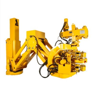
The HawkJaw 65K-950JR is a hanging unit that will spin, make up and break out drill pipe. Itis revolutionary because the tool spins and makes up drill pipe or breaks out and spins drill pipein 12 seconds or less. A patented self-energized grip system provides consistent torque values tothe drill string. Consistent torque ensures that wash outs and "post tightening" down hole do notoccur under normal conditions.
A patented adjustable wrench system eliminates the need for separate jaws, spinning wrench roll-ers or gripping dies. The HawkJaw"s modular design enables the unit to be maintained on the rigfloor.
The HawkJaw 65K-950JR provides a fast, safe and efficient method of spinning and make up orbreak out and spinning. It eliminates costly and dangerous spinning chain and rig tong accidents.
The HawkJaw improves trip time over any comparable torquing and spinning device in the in-dustry. The unit easily adapts to any land or offshore rig because it hangs in the derrick. Han-dles mounted near the control buttons enable one rig hand to move the hanging unit on and offthe pipe.
Contents Table ofOrdering Instructions 8Installation 9 Hanging Cable Location 9 HawkJaw Location 9 Hanging Cable Requirements 10 Hydraulic Requirements 11 Air Requirements 12 Raise/Lower Cylinder Hook - Up 13Operation 14 Start-up Procedure 14 Adjusting the Wrenches 15 Adjust for Make Up 15 Adjusting the Spinner 17 Adjust for Make Up 17 Rest Position 18 Adjust Spinner for Make Up (cont.) 18 Positi


 8613371530291