
hawkjaw power tong made in china

The company’s focus on vertical drilling equipment has paid off. It was awarded Manufacturer of the Year at the 2014 Oil & Gas Awards and it holds several patents for its innovative products. The company produces four main lines, the T-WREX, T-WREX Junior, HAWKJAW and SPINMASTER, and among these products Hawk Industries is able to cover a gamut of needs.
The HAWKJAW is Hawk Industries’ flagship product and has been continuously improved after years of design and testing. The make-up/break-out tool combines spinning and torque wrenches in a modular design for easy maintenance and servicing. It has a self-energized grip system and optimizes drill crew size by combining tongs, spinner and spin chains into a single unit. The HAWKJAW also improves safety with fewer cables, snub lines and pull chains required on the rig floor.
The T-WREX and T-WREX Junior feature the HAWKJAW on a pedestal-mounted configuration for remote operations. It’s ideally suited to the harsh environments of offshore drilling or large-scale land-based operations. The SPINMASTER, which the company says is one of the fastest, safest and most efficient drill pipe spinners on the market today, is available in pneumatic or hydraulic models and in two sizes. It has a high torque output of 2,272 feet per pound while its compact design makes it lighter than comparable tools. Allshouse says that all of its tools are designed for maximum flexibility.
“We try to design products that you can use on any vertical rig,” Allshouse says. “Like the HAWKJAW, it was designed to move from rig to rig, so it’s easy to take down and easy to put away. All the product lines use the same spare parts, so if you have a HAWKJAW and a T-WREX, you can interchange spare parts. We really focus on availability of parts to get the customers what they need for after-sales service and on designing flexibility into our equipment.”
When rigging up the Casing equipment make sure the Hawk jaw tong has been laid out, and then bring the Casing tong up first (before the bails), this way the tong & computer can be set up and calibrated while the Fill up tool & the auto handling equipment is installed.

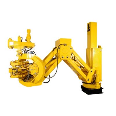
IntroductionHawk"s design philosophy is simple: Design with the end user in mind. Make it tough, dependable andeasy to maintain.Hawk has designed the HawkJaw with this same simple formula.FEATURESThe HawkJaw 65K-ALS is a hanging unit that will spin, make up and break out drill pipe. It is revolutionary because the tool spins and makes up drill pipe or breaks out and spins drill pipe in 12 secondsor less. A patented self-energized grip system provides consistent torque values to the drill string.Consistent torque ensures that wash outs and "post tightening" down hole do not occur under normalconditions.A patented adjustable wrench system eliminates the need for separate jaws, spinning wrench rollers orgripping dies. The HawkJaw"s modular design enables the unit to be maintained on the rig floor.SAFETYThe HawkJaw 65K-ALS provides a fast, safe and efficient method of spinning and make up or breakout and spinning. It eliminates costly and dangerous spinning chain and rig tong accidents.TIME AND LABOR SAVINGSThe HawkJaw improves trip time over any comparable torquing and spinning device in the industry.The unit easily adapts to any land or offshore rig because it hangs in the derrick. Handles mounted nearthe control buttons enable one rig hand to move the hanging unit on and off the pipe.Control buttons are used to grip, torque and spin drill pipe. Drillers and operators of the HawkJaw65K-ALS work more efficiently and suffer less fatigue on long round trips. The unit saves trip timebecause the HawkJaw breaks out and spins in 12 seconds or less, and makes up and spins in 10seconds or less. Crew fatigue is reduced, pipe is properly torqued and the work is efficient.
IntroductionTable of ContentsWarrantySpecification SheetOrdering InstructionsInstallationHanging Cable LocationHawkJaw LocationHanging Cable RequirementsHydraulic RequirementsAir RequirementsRaise/Lower Cylinder Hook - Up
Table of Contents (cont.)Filter MaintenanceHydraulic FilterAir FilterChanging the Hook DiesHook DiesChanging the Heel DiesTop Wrench Heel DieMiddle Wrench Heel DieBottom Wrench Heel DieSpinner MaintenanceChainDrive Roller Sprocket BearingsSpinner Grip CylindersChain Drive Shaft BearingSpinner Mount Sliding TubeReducer Gear BoxChanging the Spinner ChainChainChanging the Drive RollersDrive RollersChanging the Drive Roller Sprocket BearingsDrive Roller Sprocket BearingsChanging All Other Spinner PartsChanging the Torque CylinderTorque CylinderTorque Cylinder SealsChanging the Grip CylindersTop Grip CylinderGrip Cylinder SealsMiddle Grip CylinderGrip Cylinder SealsBottom Grip CylinderGrip Cylinder SealsChanging All Other HawkJaw PartsTrouble ShootingLeaks at Start-upMovement at Start-upRaise Button /Lower ButtonContinued on next page.
Grip ButtonSpin ButtonTorque ButtonDiesSpinnerSpinner PerformanceHawkJaw PerformanceHydraulic FluidRaise/Lower CylinderMiddle Wrench Mount ArmsExtreme Cold Weather
WarrantyHAWKJAW 65K-ALS & 100K-ALSSTANDARD WARRANTY AND FIELD SERVICEYour Hawkjaw must be free of material and workmanship defects for a period of six months from the dateof delivery. If any items fail because of a manufacturing defect within that period of time, that item will bereplaced by Hawk Industries. Hawk Industries at its discretion may extend this warranty period.Replacement of parts will be accomplished either at the factory or at a designated service point. Thisguarantee does not include the replacement of parts where failure occurred due to normal wear and tear ormisuse of the tool. Defective parts must be inspected by Hawk Industries, at its Long Beach plant, beforewarranty can be honored. Customer must obtain an RGA# (Return of Goods Authorization) from theCalifornia, USA factory.Hawk Industries" liability is limited to replacement of defective parts only and does not include the cost oflabor, communications, transportation or handling connected with the replacement of such parts.Hawk Industries will in no event be liable for consequential damages or contingent liabilities arising outof the failure of any parts to operate properly.No expressed, implied or statutory guarantee other than herein set forth is made or authorized to bemade by Hawk Industries.
CAUTIONFactory specifications for hydraulics, pneumatics, lubricants, adjustments and safety precautions as setforth in the operation and maintenance manual are for the mutual protection of the owner of the HawkJaw65K-ALS or 100K-ALS and the company. Failure to adhere to these specifications can reduce theefficiency or life of the equipment and/or cause bodily injury.
WarningThe Hawkjaw includes specially modified valves, fasteners and other components for extreme environments and service. Any attempt to substitute standard components could reduce reliability and performance, void the warranty and/or cause bodily injury.
NOTEIf the only available hydraulic power unit is open center, then a Hawk supplied hydraulicconverter (Part # J-80) is required. Running the HawkJaw with a constant volume hydraulicpower unit may result in bodily injury and will cause damage to the HawkJaw and to thehydraulic power unit.
Hanging Cable Location1. Anchor the hanging cable to a point as close to the derrick crown as possible. The longer thehanging cable, the easier the HawkJaw is to move on and off the drill pipe.2. Locate the cable hang point as high above the center of the rotary table as possible. Thecable must hang within 2"-4" ft. of the rotary table center.NOTEThe hanging cable must permit the HawkJaw to move from the drill pipe connection to themouse hole connection to the HawkJaw rest position (3"- 5" away from the rotary table).
1. Place the HawkJaw on the side of the rotary table away from the setback zone. Thisallows the drill pipe stands to swing straight from pick-up to stabbing.2. If possible, place the HawkJaw on the opposite side of the setback zone. If the rig has dualsetback zones, Step 1 applies.3. The HawkJaw may rest on the rig floor 3" -5" ft. away from the rotary table.
5/8" diameter steel cable.Appropriate hanging cable hardware for 5/8" diameter steel cable.Enough cable length to suspend the Hanger Eye (HE) 20" ft. above the rig floor.Enough cable length to allow the HawkJaw to rest on the rig floor 3"- 5" ft. away from therotary table with the lift cylinder completely stroked out. The lift cylinder is 13" ft. longwhen completely stroked out.
Hydraulic Requirements1. Pressure compensated pump set to pressure compensate at 2600 psi.2. Minimum volume of 20 gpm. 35 gpm for top performance.3. 1" minimum Pressure line. 1 1/4" Pressure line if the power unit is located more than100" apart from the HawkJaw. The hose working pressure must be 3000 psi or greater.4. 1 1/4" minimum Tank line. 500 psi minimum hose working pressure.5. Hawk approved pressure side non-collapsible type 3000 psi filter (Part # 061-H25). Initialfilter supplied with the HawkJaw. Connect the filter in line between the hydraulic powerunit and the HawkJaw.6. Hawk approved quick disconnects (Part # 061-H26). Initial quick disconnects supplied withthe HawkJaw.7. Hydraulic power unit located in a clean, dry, ventilated area.8. Enough slack in the lines for the HawkJaw to move from its rest position to the drill pipeconnection to the mouse hole connection.WARNING
The HawkJaw is a closed center systemwhich must have a pressure compensatedvolume controlled power unit. If the onlyavailable hydraulic power unit is constantvolume, then a Hawk supplied hydraulicconverter (Part # 061-J80) is required.Running the HawkJaw with a constantvolume hydraulic power unit may result inbodily injury and will cause damage to theHawkJaw and to the hydraulic power unit.
The HawkJaw must receive cleanhydraulic fluid. Running theHawkJaw without a Hawk approvedpressure-side filter (Part # 061-H25)voids the warranty and severelyshortens component life.
Air Requirements1. Clean, dry air at 100 psi @ a negligible volume.2. On board auto-dump air filter (AF) (part# 061-A22), located on board the rear of the Hawkjaw.3. Auto-dump air filter* (Part # 061-J29), must be installed in-line between the air source and theHawkJaw. Initial filter supplied with the HawkJaw.4. Enough slack in the line for the HawkJaw to move from its rest position to the drill pipe connection to the mouse hole connection.WARNINGThe HawkJaw must receive clean, dry air.Running the HawkJaw without a Hawkapproved air filter (Part # 061-J29 & 061A22 ) voids the warranty and shortenscomponent life.
Raise/Lower Cylinder Hook - Up1. Use the Raise/Lower cylinder Cap side Bolt (B) to connect the HawkJaw Suspension Ring(SR) to the Raise/Lower cylinder (C).2. Use the Raise/Lower cylinder Cap side Lock Nut (N) to secure the Raise/Lower cylinderCap side Bolt (B).3. Connect the Hanger Eye (HE) to the hanging cable.4. Connect the HawkJaw Rod side (HR) and Cap side (HC) hydraulic Leader hoses to theRaise/Lower cylinder Rod side (RR) and Cap side (RC) hoses.NOTENOTETightly connect the hose fittings. A looseMake sure the rod side of the Raise/hose connection causes a pressure drop inLower cylinder (R) connects to thethe hydraulic fluid which heats up the fluidhanging cable.and reduces component life.Part Numbers
Start-up Procedure1. Connect the air power source with the Air(A) line.2. Make sure the hydraulic reservoir is full.3. Connect the hydraulic Pressure (P), Tank(T) and Air (A) lines. "P" and "T" PortDesignations are stamped on the MainHydraulic Manifold (M).4. Check for hydraulic leaks. If leaks occur,see Trouble Shooting, p. 67.5. No motion should occur. If there ismovement of any parts on the HawkJaw,see Trouble Shooting, p. 67-69.NOTETightly connect the hose fittings. Aloose connection causes a pressure dropin the hydraulic fluid which heats up thefluid and reduces component life.
Adjust Spinner for Make Up (cont.)6. Use the rotary table to spin drillcollars larger than 5 1/2" OD.Place the HawkJaw spinner inthe rest position.Rest Position1. Remove the Spinner Arm Pins(P).2. Rotate the Spinner back to thePullback position (R).3. Insert the Spinner Arm Pins (P)with retainer clips.
Position for Make Up1. Stab the drill stand.2. Center the Suspension Ring (SR) on theLateral tilt screw (LTS).3. If the HawkJaw rests on the rig floor, useRaise (R) to raise the HawkJaw 1"- 2" ft.off the rig floor.4. If the HawkJaw is hooked back to thederrick, unhook the HawkJaw.5. Use the Control Handles (CH) to pull theHawkJaw onto the drill pipe connection.6. Use Raise (R) and Lower (L) to center theTop wrench dies (TD) and the Middlewrench dies (MD) between the shoulder(S).7. Keep the Middle wrench dies (MD) awayfrom the Hard banding (HB).8. Keep the Top wrench dies (TD) and theMiddle wrench dies (MD) away from theshoulder (S).
Position for Make Up (cont.)9. Check that the HawkJaw Topwrench (TW), Middle wrench(MW) and Bottom wrench (BW)hang straight and level when thedrill pipe is against the pipe stop.10. If the HawkJaw wrenches (TW,MW, BW) hang tilted forward orbackward, use the crescent wrenchto adjust theTurnbuckle(TB).11. If the HawkJaw wrenches (TW,MW, BW) hang sloped to theright or to the left, use the ControlHandles (CH) to back theHawkJaw off the pipe. Use Lower(L) to lower the HawkJaw to therig floor. Repeat Step 2.12. Make sure the Pipe stop (PS) isagainst the drill pipeconnection.
1. Follow the steps on pages 14-21.2. Use the Red needle adjust (RNA)to rotate the Torque gauge redneedle (RN) to the desiredtorque.3. Rotate the Torque Set knob (K)counter- clockwise as far as theTorque Set knob (K) will turn.4. Press and hold Spin (S) until thestand rotates down to theshoulder.5. Release Spin (S).6. Push in the wrench Grip (G).7. Press and hold Torque (T). Whileholding down Torque (T), rotatethe Torque Set knob (K) clockwise.8. When the Torque gauge needle(TN) reaches the desired torque,stop rotating the Torque Set knob(K).9. Release Torque (T). Immediatelyrelease the wrench Grip (G).10. The Hawkjaw torque is now setand can now be removed from thepipe.
1. Follow the steps on pages 14-21.2. Press and hold Spin (S) until thestand rotates down to theshoulder.3. Release Spin (S).4. Push in the wrench Grip (G).5. Push and hold down Torque (T).6. Watch the Torque gauge needle(TN).7. When the Torque gauge needlerises above and settles at thedesired torque (this rising aboveis a normal hydraulic adjustment),release Torque (T). Immediatelyrelease the Middle wrench Grip(MG).8. Release Torque (T). Immediatelyrelease the wrench Grip (G).9. The Hawkjaw can now be removed from the pipe.
Adjust Spinner for Break Out (cont.)6. Use the rotary table to spin drillcollars larger than 5 1/2" OD.Place the HawkJaw spinner inthe rest position.Rest Position1. Remove the Spinner Arm Pins(P).2. Rotate the Spinner back to thePullback position (R).3. Insert the Spinner Arm Pins (P)with retainer clips.
Position for Break Out1. Stab the drill stand.2. Center the Suspension Ring (SR) on theLateral tilt screw (LTS).3. If the HawkJaw rests on the rig floor, useRaise (R) to raise the HawkJaw 1"- 2" ft.off the rig floor.4. If the HawkJaw is hooked back to thederrick, unhook the HawkJaw.5. Use the Control Handles (CH) to pull theHawkJaw onto the drill pipe connection.6. Use Raise (R) and Lower (L) to center theMiddle wrench dies (MD) and the Bottomwrench dies (BD) between the shoulder(S).7. Keep the Bottom wrench dies (BD) awayfrom the Hard banding (HB).8. Keep the Middle wrench dies (MD) andthe Bottom wrench dies (BD) away fromthe shoulder (S).
9. Check that the HawkJaw Topwrench (TW), Middle wrench(MW) and Bottom wrench (BW)hang straight and level when thedrill pipe is against the pipe stop.10. If the HawkJaw wrenches (TW,MW, BW) hang tilted forward orbackward, use the crescent wrenchto adjust theTurnbuckle(TB).11. If the HawkJaw wrenches (TW,MW, BW) hang sloped to theright or to the left, use the ControlHandles (CH) to back theHawkJaw off the pipe. Use Lower(L) to lower the HawkJaw to therig floor. Repeat Step 2.12. Make sure the Pipe stop (PS) isagainst the drill pipeconnection.
1. Follow the steps on pages 14, 2430.2. Push in the wrench Grip (G).3. Push and hold down Torque (T).4. When break out occurs, releaseTorque (T). Immediately releasethe wrench Grip (G).5. If the connection does not breakout, continue to hold down Torque(T) and get another crew person torotate the Torque Set knob (K)clockwise until the connectionbreaks out. When break outoccurs, release Torque (T).Immediately release the wrenchGrip (G).6. Press and hold down Spin (S) untilthe stand pops out of the connection. Release Spin (S). If thestand will not spin, release Spin(S). Repeat Steps 3-7.7. You are now able to remove theHawkjaw from the pipe.
KNOTEIf the spinner will not open and allow the Hawkjaw torelease from the pipe, you have pulled out the bottomgrip button before releasing the spin button. Torelease the Hawkjaw from the pipe, push in themiddle grip button, and the spinner will open. Nowrelease the middle grip button and remove theHawkjaw from the pipe.
Tools RequiredGrease gunInitial Steps1. Make sure the HawkJaw is off thedrill pipe connection and in the restposition on the derrick.2. Shut down the Hydraulic powerunit.3. Press, push, and pull all controlbuttons repeatedly to bleedhydraulic pressure.4. Disconnect the Air power supply.5. Press, push, and pull all controlbuttons repeatedly to bleed airpressure.6. Assume that there is still a load onevery actuator. Proceed withcaution.
Tools RequiredGrease gunInitial Steps1. Make sure the HawkJaw is off thedrill pipe connection and in the restposition on the derrick.2. Shut down the Hydraulic powerunit.3. Press, push, and pull all controlbuttons repeatedly to bleedhydraulic pressure.4. Disconnect the Air power supply.5. Press, push, and pull all controlbuttons repeatedly to bleed airpressure.6. Assume that there is still a load onevery actuator. Proceed withcaution.
Tools RequiredGrease gunInitial Steps1. Make sure the HawkJaw is off thedrill pipe connection and in the restposition on the derrick.2. Shut down the Hydraulic powerunit.3. Press, push, and pull all controlbuttons repeatedly to bleedhydraulic pressure.4. Disconnect the Air power supply.5. Press, push, and pull all controlbuttons repeatedly to bleed airpressure.6. Assume that there is still a load onevery actuator. Proceed withcaution.
Hydraulic Filter MaintenanceChange Every 2 MonthsInitial Steps1. Depress the Red button (RB)located under the See-throughrubber weather cap (SC).2. Operate the HawkJaw.3. If the Red button pops up,proceed with Step 4.4. Make sure the HawkJaw is off thedrill pipe connection and in the restposition on the derrick.5. Shut down the Hydraulic powerunit.6. Press, push, and pull all controlbuttons repeatedly to bleedhydraulic pressure.7. Disconnect the Air power supply.8. Press, push, and pull all controlbuttons repeatedly to bleed airpressure.9. Assume that there is stillpressure in the Pressure Line.Proceed with caution.
Changing the Hook DiesBTools Required3/4" wrench, See Drawings p. 128.Initial Steps1. Make sure the HawkJaw is off thedrill pipe connection and in the restposition on the derrick.2. Shut down the Hydraulic powerunit.3. Press, push, and pull all controlbuttons repeatedly to bleedhydraulic pressure.4. Disconnect the Air power supply.5. Press, push, and pull all controlbuttons repeatedly to bleed airpressure.6. Assume that there is still a load onevery actuator. Proceed withcaution.
Changing the Heel DiesTools Required3/4" wrench, See Drawings p. 128.Initial Steps1. Make sure the HawkJaw is off thedrill pipe connection and in the restposition on the derrick.2. Shut down the Hydraulic powerunit.3. Press, push, and pull all controlbuttons repeatedly to bleedhydraulic pressure.4. Disconnect the Air power supply.5. Press, push, and pull all controlbuttons repeatedly to bleed airpressure.6. Assume that there is still a load onevery actuator. Proceed withcaution.
Changing the Heel Dies (cont.)Tools Required3/4" wrench, See Drawings p. 128.Initial Steps1. Make sure the HawkJaw is off thedrill pipe connection and in the restposition on the derrick.2. Shut down the Hydraulic powerunit.3. Press, push, and pull all controlbuttons repeatedly to bleedhydraulic pressure.4. Disconnect the Air power supply.5. Press, push, and pull all controlbuttons repeatedly to bleed airpressure.6. Assume that there is still a load onevery actuator. Proceed withcaution.
3/4" wrench, See Drawings p. 128.Initial Steps1. Make sure the HawkJaw is off thedrill pipe connection and in the restposition on the derrick.2. Shut down the Hydraulic powerunit.3. Press, push, and pull all controlbuttons repeatedly to bleedhydraulic pressure.4. Disconnect the Air power supply.5. Press, push, and pull all controlbuttons repeatedly to bleed airpressure.6. Assume that there is still a load onevery actuator. Proceed withcaution.
Chain1. Connect the air and hydraulicpower units to the HawkJaw. SeeOperation, p. 14.2. Use the 7/16" wrench to removethe rubber Safety shield bolts (B).3. Remove rubber Safety shield (S).4. While spinning after break out, fromthe back of the spinner, applyspray to chain.5. Replace rubber Safety shield (S).6. Use the 7/16" wrench to replace therubber Safety shield bolts (B).
Tools RequiredGrease gun, 7/16" wrenchInitial Steps1. Make sure the HawkJaw is off thedrill pipe connection and in the restposition on the derrick.2. Shut down the Hydraulic powerunit.3. Press, push, and pull all controlbuttons repeatedly.4. Disconnect the Air power supply.5. Press, push, and pull all controlbuttons repeatedly.6. Assume that there is still a load onevery actuator. Proceed withcaution.
Changing the Spinner ChainTools Required7/16" wrench, Hammer, Needle-NosePliersInitial Steps1. Make sure the HawkJaw is off thedrill pipe connection and in the restposition on the derrick.2. Shut down the Hydraulic powerunit.3. Press, push, and pull all controlbuttons repeatedly to bleedhydraulic pressure.4. Disconnect the Air power supply.5. Assume that there is still a load onevery actuator. Proceed withcaution.
Changing the Drive RollersTools Required3/4" wrenchInitial Steps1. Make sure the HawkJaw is off thedrill pipe connection and in the restposition on the derrick.2. Shut down the Hydraulic powerunit.3. Press, push, and pull all controlbuttons repeatedly to bleedhydraulic pressure.4. Disconnect the Air power supply.5. Assume that there is still a load onevery actuator. Proceed withcaution.
Changing the Drive Roller Sprocket BearingsTools RequiredFour 1/4"-20 x 1 1/2" Hex Tap SS(Part # 999-805867), 7/16" wrench, 3/4" wrenchInitial Steps1. Make sure the HawkJaw is off thedrill pipe connection and in the restposition on the derrick.2. Shut down the Hydraulic powerunit.3. Press, push, and pull all controlbuttons repeatedly to bleedhydraulic pressure.4. Disconnect the Air power supply.5. Assume that there is still a load onevery actuator. Proceed withcaution.
Changing the Torque CylinderTools Required1 1/8" wrench, 1" wrench, 15/16"wrench, 1/2" wrench, 9/16" wrench,Screwdriver. See Drawings, p. 128.Initial Steps1. Make sure the HawkJaw is off thedrill pipe connection and in the rest2.3.
position on the derrick.Shut down the Hydraulic powerunit.Press, push, and pull all controlbuttons repeatedly to bleedhydraulic pressure.Disconnect the Air power supply.Assume that there is still a load onevery actuator. Proceed withcaution.
Changing the Grip CylindersTools RequiredTwo 11/16" wrenches, 15/16" wrenchInitial Steps1. Make sure the HawkJaw is off thedrill pipe connection and in the restposition on the derrick.2. Shut down the Hydraulic powerunit.3. Press, push, and pull all controlbuttons repeatedly to bleedhydraulic pressure.4. Disconnect the Air power supply.5. Press, push, and pull all controlbuttons repeatedly to bleed airpressure.6. Assume that there is still a load onevery actuator. Proceed withcaution.
Changing the Grip CylindersTools RequiredTwo 11/16" wrenches, 15/16" wrench,ScrewdriverInitial Steps1. Make sure the HawkJaw is off thedrill pipe connection and in the restposition on the derrick.2. Shut down the Hydraulic powerunit.3. Press, push, and pull all controlbuttons repeatedly to bleedhydraulic pressure.4. Disconnect the Air power supply.5. Assume that there is still a load onevery actuator. Proceed withcaution.
Changing the Grip CylindersTools RequiredTwo 11/16" wrenchesInitial Steps1. Make sure the HawkJaw is off thedrill pipe connection and in the restposition on the derrick.2. Shut down the Hydraulic powerunit.3. Press, push, and pull all controlbuttons repeatedly to bleedhydraulic pressure.4. Disconnect the Air power supply.5. Press, push, and pull all controlbuttons repeatedly to bleed airpressure.6. Assume that there is still a load onevery actuator. Proceed withcaution.
Make sure the hydraulic power unit is shut down.Pull out all Grip buttons. With the Grip buttonspulled out, no air should reach the Spin hydraulicvalve. Disconnect the green air hose to Port B onthe Spin hydraulic valve. To disconnect the air hose,push the hose and collet ring into the valve pilot port.While holding down the collet ring, pull out the greenair hose. If no air comes out of the hose, replacethe Spin hydraulic valve V5. See Drawings, p. 102,108. If air comes out of the hose, replace the Airlogic manifold. See Drawings, p. 110.
Make sure the hydraulic power unit is shut down.Check to see that the Grey air hose goes to Port Aand the Blue air hose to Port B on the Torquehydraulic valve. See Drawings, p. 108.
Make sure the hydraulic power unit is shut down.Make sure the Green Raise air hose connects toPort B and the Black Lower air hose connects toPort A on the Raise/Lower hydraulic valve. SeeDrawings, p. 108.
Properly connect the Pressure and Tank lines. SeeOperation, p. 14.Properly connect the Raise/Lower Cylinder Rodside and Cap side hoses to the HawkJaw Rod side
Trouble ShootingSymptomRemedyRaise Button Push in the Raise button or the l Make sure the hydraulic power unit is shut down.Lower Button Lower button, and theHawkJaw moves opposite the
Check that air is reaching the Raise/Lowerhydraulic valve. Make sure the hydraulic powerunit is shut down. Pull out all Grip buttons. TheRaise green air hose connects to Port A on theRaise/Lower hydraulic valve V4.Disconnectthe Raise button air hose from the Raise/Lowerhydraulic valve V4. To disconnect the air hose, pushthe hose and collet ring into the valve pilot port.While holding down the collet ring, pull out the Raisegreen air hose. Place your hand over the disconnected Raise green air hose, and push in the Raiseair button. A steady blast of air should come out ofthe hose. If air comes out of the hose, replace theRaise/Lower hydraulic valve. See Drawings, p. 106.If no air comes out of the hose, the air hoses areimproperly connected within the Left control panel.SeeDrawings, p. 110. Repeat for theLower button. The black Lower air hose connects
Properly connect the Grip air hoses within the Leftcontrol handle. See Drawings, p. 110.Check to make sure the hydraulic power unit isproducing 2600 psi at 20-35 gpm..
valve. See Drawings, p. 110, 116.Check that air is reaching the Grip hydraulicvalve. Make sure the hydraulic power unit is shutdown. Pull out the Grip button. Disconnect theGrip button air hose to the Grip hydraulic valve.The bottom Grip yellow air hose connects to Griphydraulic valve V1, middle Grip orange hose toV2, and top Grip blue hose to V3. To disconnect theair hose, push the hose and collet ring into the valveport. While holding down the collet ring, pull out theGrip air hose. Place your hand over the disconnected Grip air hose, and push in the Grip air button.A steady blast of air should come out of the hose.If air comes out of the hose, replace the Griphydraulic valve. See Drawings, p. 106. If no aircomes out of the hose, the air hoses are improperly connected within the Left control handle. See
Check that the air logic manifold works. Shutdown the hydraulic power unit. Pull out all Gripbuttons. Disconnect the clear air hose fromthe Spin button air valve top left port. See Drawings, p. 112, 118. To disconnect the clear air hose,push the hose and collet ring into the valve port.While holding down the collet ring, pull out the clearair hose. Place your hand over the disconnected airhose. Push in the bottom or middle Grip button. Asteady blast of air should come out of the hose. Ifair comes out of the clear air hose when the Gripbutton is pushed in, the air logic manifold works.Connect the clear air hose to the Spin air button.Proceed to the next step. If no air comes out ofthe clear air hose when the Grip button is pushed in,check that the air hoses are properly connected
Check that the Torque button air valve works.Shut down the hydraulic power unit. Pull out allGrip buttons. Push in the Torque button. Airshould sound like it is being exhaled. Release the
valve V5 at Port A. Make sure the hydraulicpower unit is shut down. Disconnect the airsupply to the HawkJaw. Disconnect the greyTorque air hose to the Torque hydraulic valve V5Port A. Todisconnect the air hose, push thehose and collet ring into the valve pilot port. Whileholding down the collet ring, pull out the grey air hose.Place your hand over the disconnected Torque airhose.Connect the air supply to theHawkJaw. A steady blast of air should come outof the hose. If no air comes out of a hose, the airhoses are improperly connected within the Leftand Right control handles. See Drawings, p. 110, 112.If air comes out of the hose when the air supply tothe HawkJaw is
Check that air is reaching the Torque hydraulicvalve V5 at Port B. Disconnect the air supply tothe HawkJaw. Disconnect the blue Torque airhose to the Torque hydraulic valve V5 Port B. Todisconnect the air hose, push the hose and collet ringinto the valve pilot port. While holding down the colletring, pull out the blue air hose. Place your hand overthe disconnected Torque air hose.Connect the air supply to the HawkJaw. Push in theTorque air button. A steady blast of air shouldcome out of the hose. If no air comes out of ahose, the air hoses are improperly connectedwithin the Left and Right control handles. See Drawings, p. 110, 112. If air comes out of the blue hosewhen the Torque button is pressed, replace the
The middle or bottom grip button must be pushedin for the spinner to operate. Push the middlegrip and the spinner will open. Now release themiddle grip button to release the Hawkjaw from thepipe. See Operation, p.29
The hydraulic pressure is low. Increase thehydraulic pressure.Do not increase the pressure over 2600 psi, or thehydraulic fluid will pass over the relief valve andheat up the hydraulic fluid. This will cause damageto the HawkJaw and to the pump, and will severelyshorten component life.
The filter element is clogged. Replace the filterelement. See Maintenance & Repair, p. 35.Check the lead-in pressure and tank lines for anyobstructions. Also check the quick disconnectsto see that they are securely tightened. A badquick disconnect can cause the Hawkjaw to mal-
The hydraulic pressure is low. Increase thehydraulic pressure.Do not increase the pressure over 2600 psi, or thehydraulic fluid will pass over the relief valve andheat up the hydraulic fluid. This will cause damageto the HawkJaw and to the pump, and will severelyshorten component life.
114, 94, 96, 98, 100.There is a leak in the hydraulic system. Operatethe HawkJaw. Feel the outside of all actuators. Ifa portion of the cylinder surface is too hot to leaveyour hand on the cylinder, the leak is inside thecylinder. Replace the cylinder seals. If necessary,
There is a leak in the hydraulic system. Disconnect the air supply hose to the HawkJaw. Makesure the hydraulic power unit is on. If the Torquecylinder slowly extends, the leak exists inside aGrip cylinder. To check for Grip cylinder piston sealintegrity, begin with the Top Grip cylinder. Makesure no bodily parts are in the extension path ofthe cylinder rod. Slowly loosen the Cap sidehose. Check for fluid flow. If there is a piston sealleak, fluid will flow with volume out of the Cap sidefitting. Replace the seals. See Drawings, p. 96.Replace the cylinder if necessary. See Maintenance& Repair, p. 59-60. Repeat for the Middle Gripcylinder. See Drawings, p. 96. Replace the cylinderif necessary. See Maintenance & Repair, p. 61-64.Repeat for the Bottom Grip cylinder. SeeDrawings, p. 96. Replace the cylinder if necessary.See Maintenance & Repair, p. 65-66.
There is a leak in the hydraulic system. Connectthe air supply hose to the HawkJaw. Make surethe hydraulic power unit is on. Check for Torquecylinder piston seal integrity. Make sure no bodilyparts are in the extension path of the cylinderrod. Slowly loosen the Cap side hose. Check forfluid flow. If there is a piston seal leak, fluid willflow with volume out of the Cap side hydraulicfitting. Replace the seals. See Drawings, p. 94.
RemedylThere is a leak in the hydraulic system. Connectthe air supply hose to the HawkJaw. Make surethe hydraulic power unit is on. Push in the middle
Check that the pump pressure compensatorsetting is at 2600 psi. If the pump pressure compensator setting is above the pressure relief valvesetting on the HawkJaw or the pressure relief valvesetting on the hydraulic power unit, the hydraulic fluidwill heat up rapidly.
SymptomRemedyHydraulic fluid heats up.(cont.) l If there are no leaks in the hydraulic system, and thepump pressure compensator setting is at 2600psi on a known, tested hydraulic power unit, and thehydraulic power unit pressure relief valve is setabove the pump pressure compensator settingand the hydraulic fluid still heats up, then thepressure relief valve setting on the HawkJaw hasbeen changed. The pressure relief valve adjustmentis set at Hawk Industries. Under no circumstancesshould this pressure relief valve be adjusted. Adjusting the pressure relief valve setting voids thewarranty and can cause severe damage to theHawkJaw and the hydraulic power unit andshorten component life. However, if this valve hasbeen adjusted below 2600 psi, and the pressurecompensator setting is at 2600 psi, the hydraulicfluid will pass over the pressure relief valve. Thiswill heat up the hydraulic fluid rapidly. Properly setthe pressure relief valve adjustment. On aknown, tested hydraulic power unit, set the pumppressure compensator setting at 2650 psi. Usean allen wrench to rotate the pressure relief valveadjustment clockwise until the bypass sound is nolonger audible. When the bypass sound ceases, stoprotating the pressure relief valve adjustment.While holding the pressure relief valve adjustmentsteady with an allen wrench, lock in the adjustmentby tightening the pressure relief valve lock nut. Setthe pump pressure compensator setting backdown to 2600 psi. See Drawings, p. 102.
There is an inner seal leak in the cylinder. Shutdown the hydraulic power unit. Push in and pullout all Grip buttons repeatedly to bleed allhydraulic pressure.Pull out all Grip buttons. Disconnect the airsupply hose to the HawkJaw. Disconnect theRaise/Lower cylinder Hanger Eye from thehanging cable. See Installation, p. 10, Drawings, p.130. Place the Raise/Lower cylinder Rod side endon the rig floor. Connect the air supply hose tothe HawkJaw. Turn on the hydraulic powerunit. Push in the Lower button, and hold down theLower button. While holding down the Lowerbutton, check for Raise/Lower cylinder piston sealintegrity. Make sure no bodily parts are in theextension path of the cylinder rod. Slowly loosenthe HawkJaw Rod side Leader hose. Check forfluid flow. If there is a piston seal leak, fluid willflow with volume out of the Rod side leader hose.Replace the seals. See Drawings, p.100. Replacethe cylinder if necessary. See Drawings, p. 130.Push in the Raise button, and hold down the Raisebutton. While holding down the Raise button, checkfor Raise/Lower cylinder piston sealintegrity. Make sure no bodily parts are in theextension path of the cylinder rod. Slowly loosenthe HawkJaw Cap side Leader hose. Check forfluid flow. If there is a piston seal leak, fluid willflow with volume out of the Cap side leader hose.Replace the seals. See Drawings, p. 100. Replace
WarningThe Hawkjaw includes specially modifiedvalves for extreme environments. Any attemptto substitute standard components will reducereliablity and performance, and void warranty.
WarningThe Hawkjaw includes specially modifiedvalves for extreme environments. Any attemptto substitute standard components will reducereliablity and performance, and void warranty.
WarningThe Hawkjaw includes specially modifiedvalves for extreme environments. Any attemptto substitute standard components will reducereliablity and performance, and void warranty.
WarningThe Hawkjaw includes specially modifiedvalves for extreme environments. Any attemptto substitute standard components will reducereliablity and performance, and void warranty.

We"re professional hydraulic sucker rod tong manufacturers in China, providing customized products made in China with competitive price. If you are going to wholesale bulk hydraulic sucker rod tong in stock, welcome to get quotation from our factory.
XQ140 micro-marking and no-marking hydraulic power tongs is a special equipment and open power tongs which is applicable to make up or break out 41/2"-51/2" casing during oil field work over operation.
We"re professional hydraulic low stress power tong manufacturers in China, providing customized products made in China with competitive price. If you are going to wholesale bulk hydraulic low stress power tong in stock, welcome to get quotation from our factory.

TFI Emsco-1600 (1,600 hp) powered by 2-Amerimex 752 traction motors TFI Emsco-1600 (1,600 hp) powered by 2-Amerimex 752 traction motors 3-pit system (1,490 bbl) with 8 agitators 128.2 bbl premix pit built into suction 2-Derrick FLC-504
2013, TESCO 250 Ton HXI PLC Top Drive, Yoke w/ Counterbalance System, Integrated Swivel, Torque Bushing w/ Extension Arms, Torque Track, Pipe Handler System, NC 50 Load Path all on Transportation Stand (S/N 1174) 2013, TESCO HXI PLC HPU p/b CAT C27 w/ (4) SUER DANFOSS Hyd Pump Drive & Filter Manifold, Elec & Hyd Control Station w/ Hyd Reservoir / Cooler, Top Drive Power Loop on Integrated Hose Reel w/ Control Cables & Drillers Control Station (S/N 1276 & WRH03798)
2011, WARRIOR 250 Ton 250H15HR (630HP) Top Drive, w/ Counterbalance System, Integrated Swivel, Torque Bushing w/ Extension Arms, Torque Track, Pipe Handler System, NC 46 Load Path, all on Transportation Stand & 2011, WARRIOR HPU, p/b CAT C18 (630HP) w/ (2) PARKER DENISON Hyd Pump Drive & Filter Manifold, Elec & Hyd Control Station w/ Hyd Reservoir / Cooler, Top Drive Power Loop on Integrated Hose Reel w/ Control Cables
2007, TESCO HCI 500T TOP DRIVE w/ (6) Pump Hydraulic Power Unit, Model: 500/1100HP S/N: T-24499-04 TS409, p/b CAT C32 Eng S/N: TLD00677, Load Rating Thru Load Collar 500 Ton, Gearbox Ratio 2.76:1, Yoke w/ Counterbalance System, Pipe Handler System, Torque Track w/ Torque Bushing and Extension Cylinders
FILTRATION SYSTEM, ELEC & HYD CONTROL STATIONS, W RESERVOIR / COOLER, TOP DRIVE POWER LOOP ON INTEGRATED REEL SYSTEM W/ CONTROL CABLES (All MTD on a Shipping Skid)
2010 TESCO HXI 700 (750 HP) HYDRAULIC POWER UNIT P/B DETROIT 12V-2000, W/ (4) SUER DANFOSS HYD PUMP DRIVES, FILTRATION SYSTEM, ELEC & HYD CONTROL STATIONS, W RESERVOIR / COOLER, TOP DRIVE POWER LOOP ON INTEGRATED REEL SYSTEM W/ CONTROL CABLES
2010, FDS AXXON 250 TON HYDRAULIC POWER UNIT, P/B CAT C-15 (540 HP) ENG. W/ (2) PARKER DENISON HYD PUMP DRIVES, FILTER MANIFOLD, ELEC & HYD CONTROL STATIONS W/ HYD RESERVOIR / COOLER, TOP DRIVE POWER LOOP ON INTEGRATED HOSE REEL W/ CONTROL CABLES
2011, WARRIOR Hydraulic Power Unit (HPU) p/b CAT 18 (630 HP) w/ (2) PARKER DENISON Hyd Pump Drive, Filter Manifold, Elec. & Hyd Control Station w/ Hyd Reservoir / Cooler, Top Drive Power Loop on Integrated Hose Rell w/ Control Cables
GRADE S135 DRILL PIPE WITH HT 55-375 PIN 7.125” OD x 4” ID 10” TONG SPACEWITH NO HARD BANDING & WITH H- SERIES BENCHMARKS AND HT 55-375 BOX 7.125 OD x 4” ID 15” TONG SPACE WITH TCS Ti HARDBANDING & WITH H-SERIES BENCHMARKS.


 8613371530291