
milling radius without rotary table price
The channel for the slide needs to be positioned in a manner that the back of the slide is 1.98 inches away from the 3 inch point of the rotary table. And 3 inches minus 1.980 is 1.02 (3.0 - 1.980 = 1.02) so the rear of the channel needs to be machined 1.02 inches away from the center.
If you mill that channel 1.01 inches wide and so that it stops 1.02 inches from the middle of the rotary table, you should be able to set the slide in the channel so that the rotary table generates the 3 inch front radius of the RM06 in the correct position.
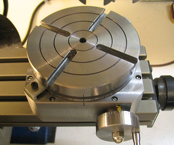
Once you have the slide positioned correctly and bolted down to your fixture, you’ll need to use an indicator to make sure the slide is perfectly straight. Adjust the straightness on your rotary table until there"s no run-out along the x axis.
Start machining the radius by using the rotary table to move the slide rather than the x/y movement of your table. Do so in 5000th increments. Machine it closer and closer to the 3 inch radius in these small increments.

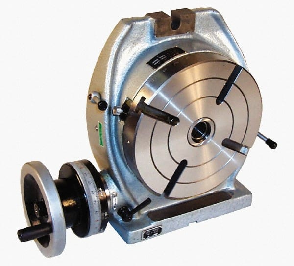
This is an accurate designed table for milling, boring and other machine tools. This table allows indexing, facing and other work to be carried out rapidly with extreme precision. Tiliting range 0-90 degrees fromread more...

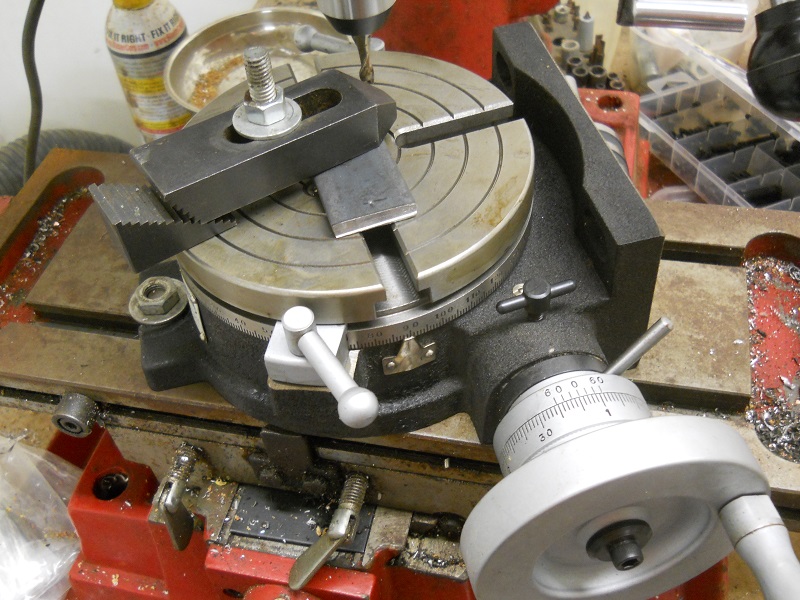
1. Build a fixture that will locate the aluminum on the rotary table so I can repeatedly use the same setup without indicating for each of the 4 corners on each piece and each of the pieces in the lot. The fixture will also hold the work piece about 1/4" above the table surface to keep it from being damaged during machining.
3. Bolt that fixture to the rotary table such that each piece to be cut will be located with the center-line of the corner radius right on top of the rotational center of the table.
7. Advance the table further left some to avoid taking too big of cut and drop the quill down so the end mill will cut the entire thickness of the 1/4" aluminum on each pass.

As for tightness of everything that is debatable as many of the Chinese imports don"t mate up part correctly. You need to make sure everything is well fitted on the mill and rotary table. This means properly fitted gibs on linear slides and a rotary table mechanism that properly mates up.
I might ask how does the mill work cutting the same material with the same tool without the rotary table. If the machine does better without the rotary then you have a couple of possibilities. The rotary table needs work. Or the hight of the rotary table gives the cutter enough leverage to hi light issues with the linear slides on the mill.
You say you have a rotary table. Use it. Make a setup similar to the photos in RichR"s post. Do conventional milling, which we would find in that last photo where the end mill rotates to the right, and the table would be rotated in a counter clockwise direction, so that the cutter and work are moving in opposite directions. For a plate 3/8 thick I suggest going with a four flute end mill. It will give a fine finish and have less chip load per tooth than a two flute.

The TR160 5 Axis Rotary Tables, manufactured by Haas, consist of dual axis Trunnion rotary table that is capable of tilting up to 160 mm. It also has a scale assessment ...
The TR210 is HAAS"S rotary table developed and configured to be integrated with HAAS"S mills 4th and 5th axis drivers to provide complete and optimum operation. It has a diameter of 210 mm made from trunnion ...
... space with high load capacity. The individual rotary tables are equipped with Harmonic Drive units, which ensure high moment load capacities and high concentricity and axial runout accuracies.
The work table is graduated 360 degrees around its circumference and is driven by a precision Worm and Gear providing a 90:1 reduction ratio. One turn of the Handle moves the Table through 4 degrees. ...
... Tilt-Yaw (A/B) two-axis rotary assembly provides high-speed machining capabilities for complex 3D part geometries. The precision-aligned system allows accurate positioning on a hemispherical surface. ...
... ) MDR two-axis rotary assembly provides high-speed machining capabilities for complex 3D part geometries. The precision-aligned system allows accurate positioning on a hemispherical surface. Uses cost-effective ...
... ) MDR two-axis rotary assembly provides high-speed machining capabilities for complex 3D part geometries. The precision-aligned system allows accurate positioning on a hemispherical surface. Uses cost-effective ...
Our FÖRSTER swivel welding tables offer maximum working comfort for all-round welding of complex assemblies. Ideal for all tasks due to a variable arrangement of our patented T-slot system.
The hydrostatic rotary tables from ZOLLERN impress with their durability and a high concentricity and axial runout accuracy. Thanks to the ZOLLERN bearing clearance compensator, the optimal pocket pressure ...
... the table is the rotation, the user may require the rotary table for drilling operations and milling. Using the servo drives in conjunction with the machine CNC control ...

Thread milling uses a standard G02 or G03 move to create the circular move in X-Y, then adds a Z move on the same block to create the thread pitch. This generates one turn of the thread;
Outside Diameter (O.D.) Thread MillingO.D. Thread Milling Example, 2.0 diameter post x 16 TPI: [1] Tool Path [2] Rapid Positioning, Turn on and off cutter compensation, [3] Start Position, [4] Arc with Z.
For many applications, (approximately 99.735% of the time, actually) you can simply allow for a radius to be in the corner. Typically this isn’t a big deal, so unless there is a very specific reason as to why having a normal radius is impossible, just go this route.
Ok, so let’s say that simply putting a radius on the inside corners won’t work for you. Maybe there’s a mating part that’s square and it needs to fit in that pocket that we were using as an example above.
Now in these examples, there is no clearance. If the mating part has a broken edge, this isn’t a problem. If it’s a sharp edge, I like to add a bit of clearance on that corner undercut to make sure it will always cut cleanly. Something like 0.010″ on a 0.25″ radius undercut usually works perfectly fine.
Here’s a pro tip: If you’re wanting something CNC machined, make the radius slightly oversized from the intended tool diameter. What this does is reduce the contact area of the cutter against the finished part geometry, and will result in a better surface finish.
My favorite way of designing this is to add the radius to match the exact cutter diameter, then offset the surface by the 0.010″ or 0.015″ – that way you get both your smooth, chatter-free surface finish and the extra corner clearance to make it work every time.
What’s basically going on here is that the practical radius of the inside corner is heavily related to the length of the tool required to cut it. So if you need a deep pocket cut, you’ll need a long tool.
Rotary broaching is really cool – it’s a way of making internal polygon geometry, and it can be done extremely quickly in a CNC mill or lathe. It can also be done for making external geometry, such as splines and hexes.
The downside to rotary broaching is that the units themselves are very expensive, so they’re typically only practical for medium or high-volume production.
Technically, you won’t get true square corners – you’ll get a tiny radius that’s equal to the radius of the wire (plus a little extra for something called a spark gap). Typically this will be in the neighborhood of 0.005″-0.006″, although it can be smaller.
You still won’t have perfect square corners, since the laser has a diameter and the kerf is a little larger than the laser, but usually this radius is so small that it’s negligible.


 8613371530291