
milling radius without rotary table pricelist
The TR160 5 Axis Rotary Tables, manufactured by Haas, consist of dual axis Trunnion rotary table that is capable of tilting up to 160 mm. It also has a scale assessment ...
The TR210 is HAAS"S rotary table developed and configured to be integrated with HAAS"S mills 4th and 5th axis drivers to provide complete and optimum operation. It has a diameter of 210 mm made from trunnion ...
... space with high load capacity. The individual rotary tables are equipped with Harmonic Drive units, which ensure high moment load capacities and high concentricity and axial runout accuracies.
The work table is graduated 360 degrees around its circumference and is driven by a precision Worm and Gear providing a 90:1 reduction ratio. One turn of the Handle moves the Table through 4 degrees. ...
... Tilt-Yaw (A/B) two-axis rotary assembly provides high-speed machining capabilities for complex 3D part geometries. The precision-aligned system allows accurate positioning on a hemispherical surface. ...
... ) MDR two-axis rotary assembly provides high-speed machining capabilities for complex 3D part geometries. The precision-aligned system allows accurate positioning on a hemispherical surface. Uses cost-effective ...
... ) MDR two-axis rotary assembly provides high-speed machining capabilities for complex 3D part geometries. The precision-aligned system allows accurate positioning on a hemispherical surface. Uses cost-effective ...
Our FÖRSTER swivel welding tables offer maximum working comfort for all-round welding of complex assemblies. Ideal for all tasks due to a variable arrangement of our patented T-slot system.
The hydrostatic rotary tables from ZOLLERN impress with their durability and a high concentricity and axial runout accuracy. Thanks to the ZOLLERN bearing clearance compensator, the optimal pocket pressure ...
... the table is the rotation, the user may require the rotary table for drilling operations and milling. Using the servo drives in conjunction with the machine CNC control ...
You say you have a rotary table. Use it. Make a setup similar to the photos in RichR"s post. Do conventional milling, which we would find in that last photo where the end mill rotates to the right, and the table would be rotated in a counter clockwise direction, so that the cutter and work are moving in opposite directions. For a plate 3/8 thick I suggest going with a four flute end mill. It will give a fine finish and have less chip load per tooth than a two flute.
CAD and a ro"tab are overkill for that port. ( It"s just a lever. No cam or follower surface evident. ) I hate indicating in a ro"tab. Radius gages and freehand grinding to a scribe line are often economical and money making.
For more exact work and for a "machined" look I use the following method. Measure the hole spacings or for a one-off use a transfer punch. Radius gauge the outside curve or insert a wood plug in the hole and pickup the radius using dividers. Rough the blank on the band-saw then drill, bore, and ream the holes. Make a pin for each of the hole diameters. It"s useful if the pins have a tapped hole in the end for a hold-down clamp. Clamp a pin in a V in the soft jaws on the vise. Slip a washer then the part over the pin. Use big vise grips to hold and rotate the part on the pin. Mill radius using reverse spiral end-mill, sneaking up on the radius. ( This takes a touch as the part wants to bounce and grab. ) Don"t go past the tangent to the sides. Leaving the ends of the radius a little short from the tangent help to avoid grabbing and looks fine when you blend. It helps to mill in two sweeps starting from the end of the radius and milling into the center then flip the part and mill the other end. Now, to blend the sides into the radii you just mount the part, side up, in the mill vice and level the part so the radii on each end of the segment are even with each other. This does not have to be exact. Just eyeball it. Slide wedges under the part to take the downward milling force. Cut the side down till it blends with the radius. Repeat for the other sides.
This is an accurate designed table for milling, boring and other machine tools. This table allows indexing, facing and other work to be carried out rapidly with extreme precision. Tiliting range 0-90 degrees fromread more...

I have used it in the vertical position to cut a 107 tooth gear which isn"t covered by any of the dividing head wheels I"ve got. I set up an excel spreadsheet with the angle required for each tooth which isn"t as easy as it sounds as the rotary table is calibrated in degrees/minutes/seconds rather than decimal degrees so it took a bit of figuring out how to do it.

The milling machine is the workhorse of the machine shop. In essence, a vertical mill is like a drill press, except it is fitted with sturdy bearings capable of handling side as well as end loads. Normally up to 85% of machining jobs will require a mill rather than a lathe. Unlike a lathe that spins the material, a mill holds the material firmly while the part is moved across a spinning tool or the spinning tool is brought down into the part. The part is moved very accurately by means of a table that can be controlled in two directions (X-axis = left/right and Y-axis=in/out). The third axis is provided by a vertical spindle (Z-axis) that moves up and down. The mill can be used for milling slots, holes or pockets, drilling, profiling, boring, and surfacing. Most milling is done using “end mills” that look much like a drill bit except they are capable of cutting on the sides as well as on the end. They are held in an end mill holder and can cut slots, pockets or flat surfaces. A drill chuck can be used for holding drill bits. For larger surfaces, a “fly cutter” is used. It is a single-pointed tool that spins in a large arc and is brought across the surface of the part to flatten it.
The 4th axis of a milling machine is the rotary axis (called the A-axis) provided by an optional rotary table. A mill with a rotary table is a powerful combination. Technically, a mill with a rotary table is the minimum combination of tooling required to reproduce itself: that is, make another mill and rotary table.
Leadscrew—The threaded screws that move the table left/right and in/out as well as the vertical axis up and down. They are driven by handwheels marked in .001” or .01 mm increments.
Leadscrew Locking Lever—Located on the back side of the vertical column, this locking lever locks against the saddle nut to prevent unwanted movement of the Z-axis during machining operations. Manual machines are fitted with a standard on/off locking lever. CNC machines are fitted with an adjustable locking lever that can be used to control backlash in the Z-axis. This function is available as an option on any manual mill as well. (P/N 4017U inch or 4117U metric)
X-axis Locking Screw—A screw that goes through the barrel lock on the front of the saddle to lock the table in place during machining operations where movement is not required or desired.
Backlash Locks—The lock works like tightening two nuts against each other on a threaded shaft to reduce play in the threads. Backlash is the pause in travel when changing the direction of rotation of any threaded crew. Because both sides of the thread don’t rub on the nut at the same time (they would quickly wear out), one surface is pulling or pushing the nut when the screw is turned. When you stop and change directions, the screw turns a slight amount while the thread picks up the other side and begins to move the nut in the other direction. The looser the fit of the threads, the more “backlash” occurs. In essence, it is the amount you can turn the handwheel in the reverse direction before movement occurs on an axis. An adjustment is provided on the X- and Y-axes to reduce the leadscrew backlash. Backlash is not a “fault” of a machine; it is simply a physical reality that must be taken into account when machining. You adjust to a known or acceptable amount using the locks and then remove it from the machining operation by always approaching your cut from the same direction with the backlash already eliminated before the cut begins.
Alignment Key—A precision ground key that fits in a slot in the column saddle to keep the headstock aligned straight up and down. A second slot is also provided to locate the headstock at 90° for horizontal milling. Removing this key and rotating the headstock allows bevels to be cut at any angle. An approximate angle scale is laser-engraved into the saddle for reference.
Rotary Column Attachment—This function allows the vertical column to be rotated from side to side to do angled milling or drilling. It is included in the design of the 2000-series mills or can be added as an option (P/N 3700) to 5000/5400-series mills.
Adjustable “Zero” Handwheels—On base model machines, plain handwheels are used. They are laser engraved with 50 marks (inch) or 100 marks (metric) and numbers for reference. Adjustable zero handwheels allow you to stop at any given point, loosen a knurled wheel in the center of the handwheel and rotate the laser engraved collar back to the zero mark before starting the next cut without moving the position of the handwheel. This means each time you are starting from zero rather than from a random number, making your depth and cut calculations easier. This eventually means fewer mistakes. 4400- and 4500-series lathes and 5400- and 2000-series mills include these upgraded handwheels as standard equipment.
4th Axis—In milling, in addition to the X-, Y- and Z-axis, the 4th axis is called the A-axis or rotary axis and is provided by an optional rotary table. Sherline offers manual (P/N 3700) or CNC (P/N 8700 or 8730) rotary tables.
End Mills—They look like drill bits but are sharpened on the sides as well as the ends. Held in an end mill holder, they are used to cut slots, pockets or surfaces. End mills are normally flat but “ball end” mills are also available that have a round end for leaving a radius in the corner of a pocket or a round-bottomed slot. End mills can have two, three or four flutes (spiral cuts) in the sides. Generally, fewer flutes are better for softer materials like aluminum because they don’t clog as easily, while more flutes (and slower cutting speeds) are better for steels that don’t allow as aggressive a cut and produce fewer chips per cut.
Mill Vise—A small vise that is clamped to the mill table and holds parts for milling. It is different from the more common drill press vise in that it tightens with a pull-down function that helps hold the part down as well as in to counter the forces of milling. It is also accurately machined so it can be aligned in the machine for accurate cuts.
Hold-down Set—A series of adjustable clamps that are used to hold parts to the mill table for milling. They can be used on large or uneven parts like castings.
Thread milling uses a standard G02 or G03 move to create the circular move in X-Y, then adds a Z move on the same block to create the thread pitch. This generates one turn of the thread;
Outside Diameter (O.D.) Thread MillingO.D. Thread Milling Example, 2.0 diameter post x 16 TPI: [1] Tool Path [2] Rapid Positioning, Turn on and off cutter compensation, [3] Start Position, [4] Arc with Z.
Rapid-position the tool to the center of the circle. To remove all the material inside the circle, use I and Q values less than the tool diameter and a K value equal to the circle radius. To cut a circle radius only, use an I value set to the radius and no K or Q value.
These G codes assume cutter compensation, so you do not need to program G41 or G42 in the program block. However, you must include a D offset number, for cutter radius or diameter, to adjust the circle diameter.

That is precisely the way a CNC mill works and it will get the job done if the steps are small enough and you have enough patience. I once had to mill a .012" square hole in a piece of brass shim for an optical application. I used a .005" diameter end mill and worked under a microscope to see what was going on. The individual steps were very apparent at that level. Obviously a larger end mill will make the steps less apparent. I think I would get looking for a rotary table though, it"s gonna take a lot of time to create an arc with that technique.

The Taig Micro Mill is an “overbuilt” miniature milling machine. The liberal use of steel in its construction affords superior rigidity and the ability to work on hard metals. It is equipped with a 6-speed pulley system, which yields spindle speeds from 525–5,200 rpm on the manual machine, or 1,000–10,000 RPM on the CNC and CNC-ready models.
The shortbed is 15.5″ long, with a travel of 9.5″ in the x axis. The longbed is 18.4″ long, with 12″ travel in x. The table size is 3.5″ × 15.5″ for the shortbed mills or 3.5″ × 18.5″ for the longbed mills. The longbed is particularly handy if you’re using Taig’s 4th axis attachment, which takes up some space on the bed. Most people think the extra x travel is worth the extra money, but if someone is very tight on space, or only works on very small projects, they might opt for the shorter bed.
By using a longer screw and adding a spacer between the column and base, it is possible to add an extra inch of travel to the y axis, which can be critical for certain projects. The standard y axis travel is 5.5″; this modification extends that to 6.5″. It’s important to note, though, that using this extra travel will require affixing a plate to the mill bed (not supplied) that projects out over the front edge of the bed to support the workpiece, if it’s not capable of supporting itself during the milling process. This option is not available on shortbed mills based on the 2018. The option is slightly cheaper on mills with leadscrews.
1030 4-Jaw Chuck: This 3¼″ diameter all-steel chuck has 4 heat-treated reversable steel jaws that can move independently and are tightened with an Allen key, allowing square rectangular, octagonal, or round stock to be centered precisely and held firmly. Its internal ¾″-16 tpi threads match the rotary table adapter. If you’re only buying one chuck to use with the rotary table, this is the one we usually recommend. Note: these chucks are only used on certain lathes and the rotary table; their internal threads don’t match the 22mm–1.5mm threads of the ER spindle.
1050 3-Jaw Scroll Chuck: This 3-jaw chuck can hold round and hexagonal stock. Its internal ¾″-16 tpi threads match the rotary table adapter. Unlike the 4 jaw chuck, the jaws on the 3-jaw chuck all move at the same time, allowing the user to load and unload parts very quickly, using the supplied “Tommy” bars. The soft aluminum jaws on this chuck can be easily machined for greater concentricity to the rotary table’s rotation, or to fixture special parts. Additional soft jaw sets (part 1151) can be purchased if needed. Note: these chucks are only used on certain lathes and the rotary table; their internal threads don’t match the 22mm–1.5mm threads of the ER spindle.
1060 4-Jaw Scroll Chuck: This 4-jaw chuck is good for holding square, round, or octagonal stock, and can quickly load and unload parts. Its internal ¾″-16 tpi threads match the rotary table adapter. It holds more firmly than the 3-jaw scroll chuck and its aluminum soft jaws can also be machined for greater concentricity or for fixturing special parts. Additional soft jaw sets (part 1161) can be purchased if needed. Note: these chucks are only used on certain lathes and the rotary table; their internal threads don’t match the 22mm–1.5mm threads of the ER spindle.
End Mills: End mills are the tools normally used to cut metal with a milling machine. There are lots of variations in these, but this is a good starter set consisting of five double-ended cutters with flat ends. Sizes are ¹⁄₁₆″ ³⁄₃₂″ ⅛″ ⁵⁄₃₂″ ³⁄₁₆″.
Edge Finder: When machining parts precisely, it’s helpful to know exactly where the edge of the workpiece is. Using this ¼″ shank edge finder, you can do that without damaging your tool or your part. Just touch off the side of the edge finder to the edge of your workpiece, subtract the .1″ radius of the tip, and you’ve got it.

Rotary Milling Tableoffered comes in quality metal construction finish and is made available at competitive prices. These full size milling tables come developed using high strength resin sand casting as well as feature 3-axis line rail and high speed spindle unit. Some of its features include separate hand wheel support; turntable style tool magazine; pneumatic broach system; adjustment support for shim and screw; automatic intermittent lubrication.
A rotary desk is the revolving plate at the rig"s drill ground that turns the drill string in a clockwise course. The rotary table surrounds the 4 or six-sided kelly bushing and kelly force to which the drill string is hooked up, moving the strength from the rig"s force device to the drill string and bit.
The rotary table hyperlinks the rig"s strength deliver to the drill string, it may be described as a capture. most rigs have a rotary desk due to the fact the top mover for the drill string, however, top strength structures that permit continuous rotation of the drill string have changed the rotary desk, the kelly bushing and the kelly strain in a few rigs, because of changes in trenchless construction requirements.
The rotary force table is familiar in pinnacle-pressure rigs, that is, those who have their pressure motor at the top of the rig. Drill string sections are first linked to the bottom hole assembly. As drill string sections bypass into the bore, extra sections of drill string are connected to the pinnacle strain motor and to sections inside the bore, constructing the drill string from the top. the ones sections of drill string screw collectively the usage of a clockwise movement. The rotary desk -- which turns clockwise -- is used to tighten the segments of the drill string.

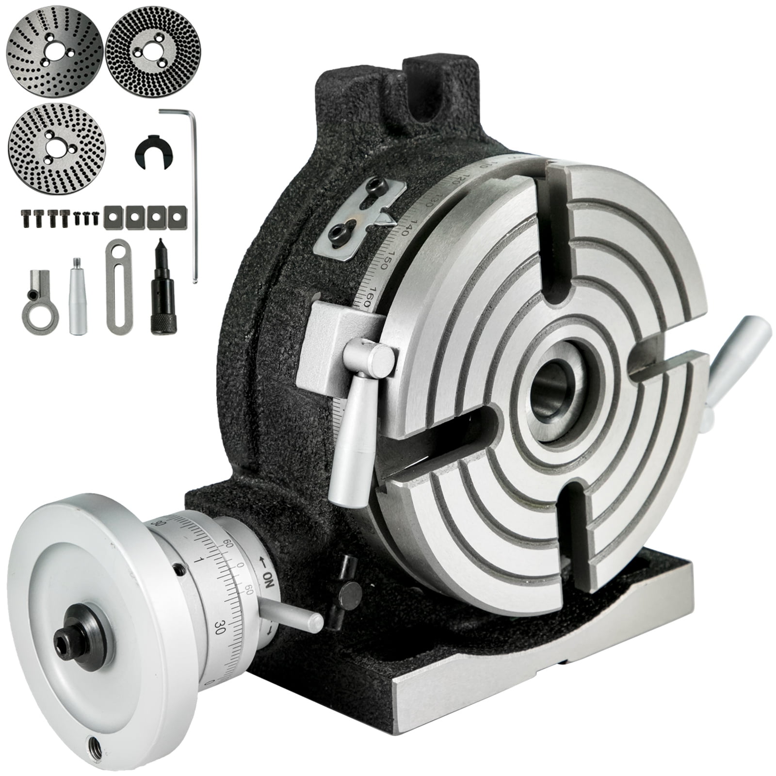
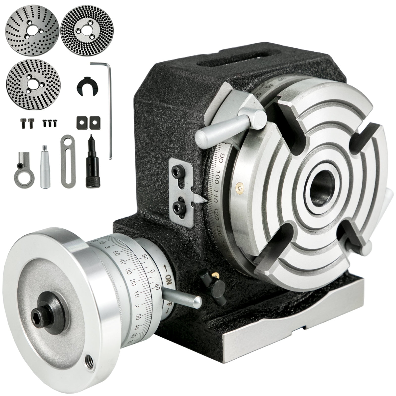
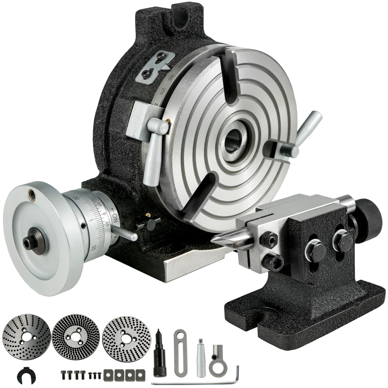
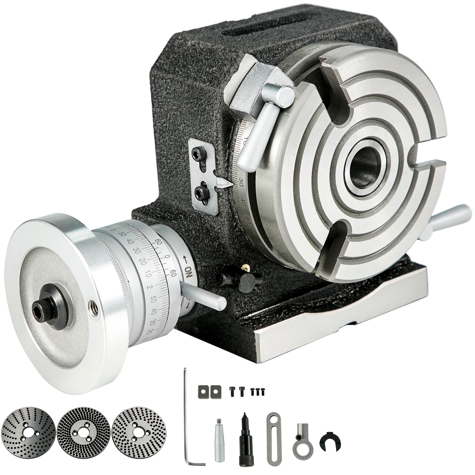
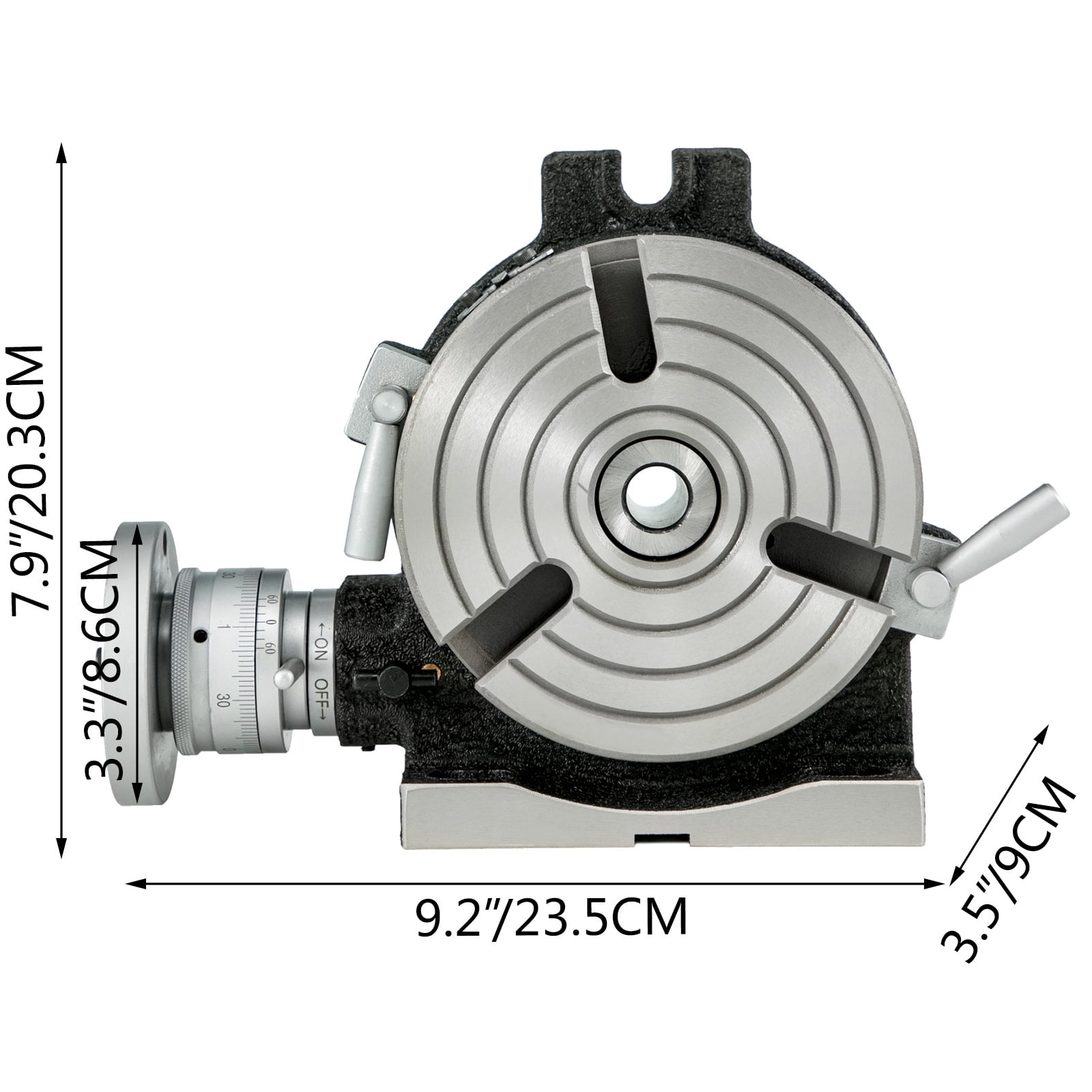
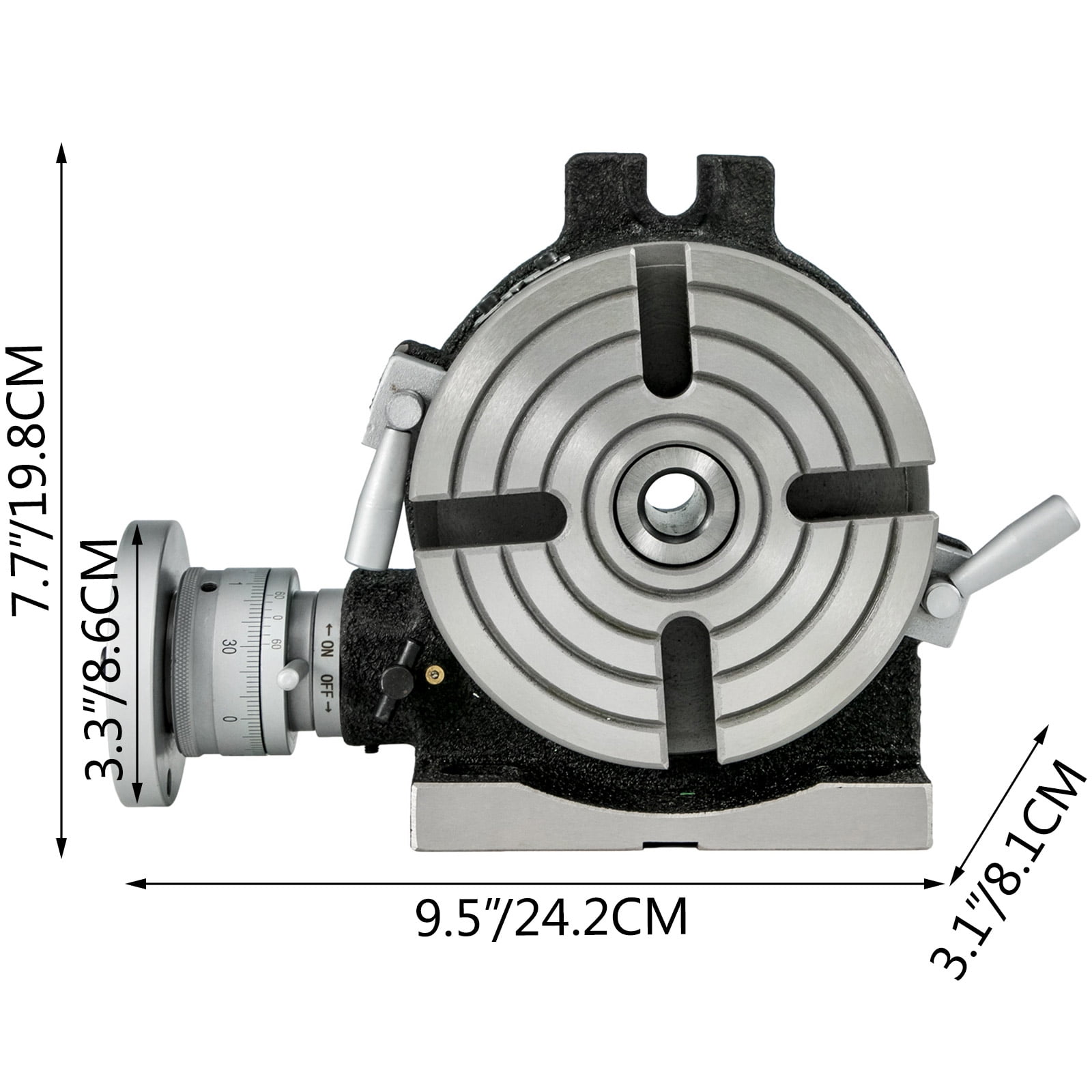
The vertical & horizontal rotary table, one of the main accessories of the milling machine, is a precision work positioning device. This machine is widely used in metalworking, enabling the operator to drill or cut work at exact intervals around a fixed axis.
It can be mounted "flat," with the table rotating around a vertical axis, in the same plane as the cutter of a vertical milling machine. Or, mounted the rotary table on its end (or mount it "flat" on a 90° angle plate) so that it rotates about a horizontal axis. In this configuration, a tail stock can also be used, thus holding the workpiece "between centers."
It"s not difficult for you to adjust the rotary table milling machine. What you should do is to adjust the handle to the position where you want because the precise scale is marked on the dial.
Except for the 5.9""(150 mm) rotary machine table, we also offer you four locating blocks. The center can be corrected quickly and accurately by the Key guide block.


 8613371530291