
api safety valve free sample

DATA SHEET PRESSURE SAFETY VALVClient :Location :Service :Qty : TECHNICAL SPECIFICATIOTag NumberService DescriptionLine Number / ScheduleP&ID NumberManufacturerModel NumberSerial NumberFull / Semi NozzleSafety or Relief or Safety ReliefType (Conv, Bellows, Pilot Op.)Bonnet TypeQuantity CONNECTIONSize Inlet OutletFlange Rating or ScrewedType of Facing FLUID DATA RELIEF CONDITION BLOCKED OUTLETFluid & StateMol. Wt. Op. Sp Gr.Op. Pres. (psig) Set Pres. (psig)Op. Temp. (F) Relieving Temp. (F)Des. Pres. (psig) Des. Temp. (F)Max. Accumulated Pressure , %Ratio of Specific Heats (Cp/Cv)Vapor Mass Flow Rate/ Liquid Calc.Compressibility FactorVapor Mass Flow Rate/ Liquid Req.Atmospheric PressureOperating Viscosity (cP) DISCHARGE CONDITION Superimposed Allowable Built-Up Back Pressure Total (Max.) Calculated Buit-UpLatent Heat of VaporizationCoefficient of Discharge (Kd)Correction Factor Vapor (Kb) CALCULATIONTotal Rated Flowrate (Valve Capacity)Calc. Valve Area (sq. in)Sel. Valve Area (sq. in)Orifice Designation MATERIALBody BonnetNozzle DiskGuide RingSpring Bellows ACCESSORIESCap : Screwed / BoltedLever : Plain / PackedBonnet Vent Test Gauge BASIS OF SELECTIONCode API RP 520 / ASME VIII / API 526 /API 527Fire (by Process)Failure Case (by Process)Valve Discharge ToEquipment Protected NOTE 0 0
DATA SHEETPRESSURE SAFETY VALVE Data Sheet No. : - Doc. No. : - Tag No. : Page. No. : 3 ofECHNICAL SPECIFICATION

A safety valve must always be sized and able to vent any source of steam so that the pressure within the protected apparatus cannot exceed the maximum allowable accumulated pressure (MAAP). This not only means that the valve has to be positioned correctly, but that it is also correctly set. The safety valve must then also be sized correctly, enabling it to pass the required amount of steam at the required pressure under all possible fault conditions.
Once the type of safety valve has been established, along with its set pressure and its position in the system, it is necessary to calculate the required discharge capacity of the valve. Once this is known, the required orifice area and nominal size can be determined using the manufacturer’s specifications.
In order to establish the maximum capacity required, the potential flow through all the relevant branches, upstream of the valve, need to be considered.
In applications where there is more than one possible flow path, the sizing of the safety valve becomes more complicated, as there may be a number of alternative methods of determining its size. Where more than one potential flow path exists, the following alternatives should be considered:
This choice is determined by the risk of two or more devices failing simultaneously. If there is the slightest chance that this may occur, the valve must be sized to allow the combined flows of the failed devices to be discharged. However, where the risk is negligible, cost advantages may dictate that the valve should only be sized on the highest fault flow. The choice of method ultimately lies with the company responsible for insuring the plant.
For example, consider the pressure vessel and automatic pump-trap (APT) system as shown in Figure 9.4.1. The unlikely situation is that both the APT and pressure reducing valve (PRV ‘A’) could fail simultaneously. The discharge capacity of safety valve ‘A’ would either be the fault load of the largest PRV, or alternatively, the combined fault load of both the APT and PRV ‘A’.
This document recommends that where multiple flow paths exist, any relevant safety valve should, at all times, be sized on the possibility that relevant upstream pressure control valves may fail simultaneously.
The supply pressure of this system (Figure 9.4.2) is limited by an upstream safety valve with a set pressure of 11.6 bar g. The fault flow through the PRV can be determined using the steam mass flow equation (Equation 3.21.2):
Once the fault load has been determined, it is usually sufficient to size the safety valve using the manufacturer’s capacity charts. A typical example of a capacity chart is shown in Figure 9.4.3. By knowing the required set pressure and discharge capacity, it is possible to select a suitable nominal size. In this example, the set pressure is 4 bar g and the fault flow is 953 kg/h. A DN32/50 safety valve is required with a capacity of 1 284 kg/h.
Coefficients of discharge are specific to any particular safety valve range and will be approved by the manufacturer. If the valve is independently approved, it is given a ‘certified coefficient of discharge’.
This figure is often derated by further multiplying it by a safety factor 0.9, to give a derated coefficient of discharge. Derated coefficient of discharge is termed Kdr= Kd x 0.9
Critical and sub-critical flow - the flow of gas or vapour through an orifice, such as the flow area of a safety valve, increases as the downstream pressure is decreased. This holds true until the critical pressure is reached, and critical flow is achieved. At this point, any further decrease in the downstream pressure will not result in any further increase in flow.
A relationship (called the critical pressure ratio) exists between the critical pressure and the actual relieving pressure, and, for gases flowing through safety valves, is shown by Equation 9.4.2.
Overpressure - Before sizing, the design overpressure of the valve must be established. It is not permitted to calculate the capacity of the valve at a lower overpressure than that at which the coefficient of discharge was established. It is however, permitted to use a higher overpressure (see Table 9.2.1, Module 9.2, for typical overpressure values). For DIN type full lift (Vollhub) valves, the design lift must be achieved at 5% overpressure, but for sizing purposes, an overpressure value of 10% may be used.
For liquid applications, the overpressure is 10% according to AD-Merkblatt A2, DIN 3320, TRD 421 and ASME, but for non-certified ASME valves, it is quite common for a figure of 25% to be used.
The ASME/API RP 520 and EN ISO 4126 standards, however, require an additional backpressure correction factor to be determined and then incorporated in the relevant equation.
Two-phase flow - When sizing safety valves for boiling liquids (e.g. hot water) consideration must be given to vaporisation (flashing) during discharge. It is assumed that the medium is in liquid state when the safety valve is closed and that, when the safety valve opens, part of the liquid vaporises due to the drop in pressure through the safety valve. The resulting flow is referred to as two-phase flow.
The required flow area has to be calculated for the liquid and vapour components of the discharged fluid. The sum of these two areas is then used to select the appropriate orifice size from the chosen valve range. (see Example 9.4.3)
The primary purpose of a safety valve is to protect life, property and the environment. Safety valves are designed to open and release excess pressure from vessels or equipment and then close again.
The function of safety valves differs depending on the load or main type of the valve. The main types of safety valves are spring-loaded, weight-loaded and controlled safety valves.
Regardless of the type or load, safety valves are set to a specific set pressure at which the medium is discharged in a controlled manner, thus preventing overpressure of the equipment. In dependence of several parameters such as the contained medium, the set pressure is individual for each safety application.

The primary purpose of a pressure relief valve is to protect life, property and the environment. Pressure relief valves are designed to open and release excess pressure from vessels or equipment and then close again.
The function of pressure relief valves differs depending on the main type or loading principle of the valve. The main types of pressure relief valves are spring-loaded, weight-loaded and controlled pressure relief valves.
Regardless of the type or load, pressure relief valves are set to a specific set pressure at which the medium is discharged in a controlled manner, thus preventing overpressure of the equipment. In dependence of several parameters such as the contained medium, the set pressure is individual for each safety application.

Surface-controlled subsurface safety valves (SCSSVs) are critical components of well completions, preventing uncontrolled flow in the case of catastrophic damage to wellhead equipment. Fail-safe closure must be certain to ensure proper security of the well. However, this is not the only function in which it must be reliable—the valve must remain open to produce the well. Schlumberger surface controlled subsurface safety valves exceed all ISO 10432 and API Spec 14A requirements for pressure integrity, leakage acceptance criteria, and slam closure.
Through decades of innovation and experience, Schlumberger safety valve flapper systems are proven robust and reliable. The multizone dynamic seal technology for hydraulic actuation of subsurface safety valves is a further improvement in reliability performance when compared with traditional seal systems in the industry.
The multizone seal technology is currently available in the GeoGuard high-performance deepwater safety valves, which is validated to API Spec 14A V1 and V1-H.
![]()
Safety valves and pressure relief valves are crucial for one main reason: safety. This means safety for the plant and equipment as well as safety for plant personnel and the surrounding environment.
Safety valves and pressure relief valves protect vessels, piping systems, and equipment from overpressure, which, if unchecked, can not only damage a system but potentially cause an explosion. Because these valves play such an important role, it’s absolutely essential that the right valve is used every time.
The valve size must correspond to the size of the inlet and discharge piping. The National Board specifies that the both the inlet piping and the discharge piping connected to the valve must be at least as large as the inlet/discharge opening on the valve itself.
The connection types are also important. For example, is the connection male or female? Flanged? All of these factors help determine which valve to use.
The set pressure of the valve must not exceed the maximum allowable working pressure (MAWP) of the boiler or other vessel. What this means is that the valve must open at or below the MAWP of the equipment. In turn, the MAWP of the equipment should be at least 10% greater than the highest expected operating pressure under normal circumstances.
Temperature affects the volume and viscosity of the gas or liquid flowing through the system. Temperature also helps determine the ideal material of construction for the valve. For example, steel valves can handle higher operating temperatures than valves made of either bronze or iron. Both the operating and the relieving temperature must be taken into account.
Back pressure, which may be constant or variable, is pressure on the outlet side of the pressure relief valve as a result of the pressure in the discharge system. It can affect the set pressure of the upstream valve and cause it to pop open repeatedly, which can damage the valve.
For installations with variable back pressure, valves should be selected so that the back pressure doesn’t exceed 10% of the valve set pressure. For installations with high levels of constant back pressure, a bellows-sealed valve or pilot-operated valve may be required.
Different types of service (steam, air, gas, etc.) require different valves. In addition, the valve material of construction needs to be appropriate for the service. For example, valves made of stainless steel are preferable for corrosive media.
Safety valves and relief valves must be able to relieve pressure at a certain capacity. The required capacity is determined by several factors including the geometry of the valve, the temperature of the media, and the relief discharge area.
These are just the basic factors that must be considered when selecting and sizing safety valves and relief valves. You must also consider the physical dimensions of the equipment and the plant, as well as other factors related to the environment in which the valve will operate.
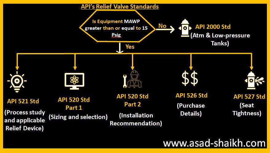
**Update to this article, June 7, 2022 : If you found this article helpful, here is a link to another article I recently found that does a nice job explaining the topic: ENGINEERS BEWARE: API vs ASME Relief Valve Orifice Size – Petro Chem Engineering (petrochemengg.com)
NOTE: this article is written to an audience that is familiar with PSVs, PSV sizing, and API and ASME standards at a basic level. I initially wrote this article in early 2017, and due to some great input and questions made significant revisions to increase clarity in mid-2018. I hope it is helpful to you, please send me a message with any comments/questions!
If you"ve ever sized/selected a Pressure Safety-Relief Valve (PSV) using vendor sizing programs or good-old hand calculations, you"ve probably run into a very strange anomaly: Why does a PSV orifice size change between American Petroleum Institute (API) and American Society of Mechanical Engineers (ASME) data sets? What is an "effective" orifice area? How do I know which standard to use when selecting a PSV?
Usually, this issue is one of curiosity and doesn"t affect the end result of what valve is chosen. Common practice is to default to API sizing equations and parameters, and only use ASME data sets for situations outside of the API letter-designations. But what if I told you that approach is likely causing you to oversize about 10% of your PSVs and their respective piping systems?
Most of the time simply using API data sets is fine. And I should note that this is a conservative approach, so you won’t make a mistake doing this. But did you know that PSVs are certified to ASME capacities, not API? And did you know those ASME capacities are nearly always higher than the API ones? I’m guessing you don’t, because there are very few resources available that speak to this topic. I’ve found it common for engineers to understand API 520 quite well, but have a very limited working knowledge of how the ASME BPVC comes into play.
Too often, we leave that third part out of the process, and simply calculate relief loads and select valves using API techniques, without ever checking our selection against certified ASME data. Proper application of these standards is the first key point of this article:
Initial sizing and valve selection is done using API equations, and final valve selection and certification is done using ASME-certified coefficients and capacities.
When sizing a PSV, the sizing equations are always API 520. When a PSV is certified, it is always certified to ASME BPVC (whether one “selects” ASME certification or not!) It"s important to remember that the ASME BPVC is the "code", the standard to which we must design. API 520/526 are "recommended practices" which were developed to give engineers a tool to meet the ASME requirements. Another way to look at it: ASME BPVC sets the goal, API 520/526 provide the instructions, and ASME has the final say.
The BPVC is an enormous code, and not reviewed in detail here. On the subject of PSVs, it basically says that a PSV must be capable of relieving the required load, and it must be tested in a specific manner to be certified to do so. If a valve is tested per the specific directions in the BPVC, it will be ASME certified and receive an ASME UV stamp.
The first thing API does is attempt to standardize physical PSV sizes and design, and it does so in API RP 526, which is targeted at PSV manufacturers. API provides pre-defined valve sizes, with letter designations D through T (API 526). It also defines other details directed toward valve manufacturers (such as temperature ratings). All of this is intended as minimum design standards, and manufacturers are free to exceed these parameters as they wish.
The second thing API does is provide standardized equations and parameters to use when trying to figure out just what size of a PSV one needs for a particular scenario. The equations account for design parameters that ASME doesn"t speak to, such as specific fluid properties, backpressures, critical flow, two-phase flow, and many other aspects of fluid dynamics that will affect the ability of a particular valve to relieve a required load.
API sizing equations are by nature theoretical, standardized, and use default or "dummy" values for several sizing parameters that may or may not reflect the actual values for any specific valve.
API RP 520 very clearly talks about this, and emphasizes that the intended use of its equations is to determine a preliminary valve size, which should be verified with actual data. API intends PSV sizing to be a two-step process, but we are often unaware of this because we (gasp) don’t read the full standard, and/or rely solely on vendor sizing software that hides the iteration from us. See API 520, part 1, section 5.2 for further explanation.
When valves are built, they are built to the API RP 526 standard, however, as one might imagine, when valves are actually tested and certified, the results don’t match up identically to the theoretical values that were calculated. This is where API and ASME intersect; we switch from calculations (API) which were used as a basis to design the valve, to actual empirical data (ASME) to certify the valve. When a valve manufacturer gets the UV code stamp that certifies the valve orifice size and capacity, it is based on actual test results, not API sizing standards. And ASME (which came first) does not have tiered letter designations. The typical D, E, F, etc. sizes we refer to are strictly an API tool, and ASME’s capacity certifications are completely independent of them!
3. A third-party Engineer (you), trying to select a PSV, runs a sizing calculation using API 520 equations on ABC Valve Company"s sizing software, gets a result that requires 4.66in2 to relieve the load, and is now thoroughly confused on what size valve to select.
If one selects the API data set on the sizing software in this example, it will automatically eliminate N-orifice valves as an option, and bump the user up to a P-orifice. However, if one simply selects the ASME data set, the N-orifice valve magically reappears as an option. How can this be? Will the N-orifice work or not?
The short answer is yes, it is certified to an actual area of 4.90in2. So the “N” orifice for this specific PSV will work, and is certified to do so, in this application. Remember: use API to get you close, and ASME to confirm the final answer.
Digest that for a moment. If you’ve sized and purchased more than a dozen PSVs, chances are you have inadvertently selected a PSV a full size larger than you needed to, in a situation much like our example, simply because you chose a PSV based on its API “rating” rather than its real, certified, stamped ASME rating. If that was a small valve, impact was probably nil. But what if this happened on a valve that resulted in selecting a 8x10 PSV when you could have used a 6x8?
If you’re like me, that answer isn’t very satisfying. Why on earth is this so confusing? How can you simply hit a button on the sizing program and a different size of valve is suddenly acceptable? The key lies how the main coefficient of discharge, Kd, is handled, and how capacities are determined.
There are several K values used in API calculations, all of which have generic values defined in API 520 that can be used for preliminary sizing. These are the numbers used in initial sizing calculations to get us close, then (if we do this correctly) replaced with the actual/tested/empirical/ASME values when we get a certified valve. Remember, anytime you hear “certified” or “stamped”, think ASME.
Let’s take the numbers from the example above, which came from an attempt to size a valve for liquid relief. API says to use a value of Kd=0.65 for liquid relief. If one uses the API data set on the vendor software, then the calculation stops here, and you get a required area of 4.66in2. When you select a valve, you’re comparing that to the API effective (actual) area of an N orifice, which is 4.34 in2, which is obviously too small and you’d logically step up to a P orifice. However….
Remember that the API N-orifice area is just the benchmark, a minimum requirement, and may or may not (most likely not) reflect the actual area of a real-life PSV. Once a valve is selected, all of those K values and capacities should be replaced with actual ASME-certified K values, also determined by testing, that are specific to each valve model, and the calculations performed again.
Normally, ASME-certified K-values are smaller than the API dummy values, driving up the required orifice area. So valve manufacturers have to over-design their valves to make up for it, resulting in ASME-certified areas and capacities that typically exceed the benchmark API ones. The end result of all this?
It (almost) all boils down to one sneaky little sentence in the ASME BPVC which mandates a 10% safety factor on the empirically-determined Kd that “de-rates” the valve (see ASME BPVC Section VIII, UG-131.e.2). This tidbit seems to be a little-known fact that is key to proper PSV sizing and selection, because as engineers we often pile safety factors upon each other and oversize our equipment. I cannot highlight this enough:
I mentioned above that ASME K values are nearly always lower than API values, due to this 10% de-rating. The PSV in our example scenario has a determined Kd of 0.73, which is adjusted down by 10% for a final AMSE Kd of 0.66, slightly higher than the dummy API value (that just means that this particular valve proved it could do about 11% better than the minimum theoretical flow calculated by API when it was tested). So, for our valve in question, the Required ASME area is slightly less than the API area. This is atypical, but not unheard of, and again points to the importance of checking the ASME ratings of any valve you select, and comparing against the API benchmarks.
When you choose to use the ASME data on a specific valve, it’s not just the Kd sizing factor that changes; the actual orifice area and therefore the capacity of the valve also adjusts to empirical, certified values. You can generally expect both values to increase over the API values.
Why is this? Simply that any given real-world valve is usually over-designed so that it will meet and exceed the required minimum capacity of its corresponding API size. What a simple concept, but so often overlooked by engineers!
Back to our example scenario: even though the ASME Kd, and hence required area, adjustment had a negligible effect, the actual ASME orifice area, and hence capacity, is significantly higher than the listed API area and capacity for an N-orifice. Below is a summary:API N Orifice: 4.340 in2
*Note: this is data from a real case; the specific PSV make/model is omitted. Did you catch the result? The actual, certified capacity of this valve is nearly 13% higher than the generic N-orifice valve, and that includes its 10% safety factor!
With this adjusted orifice area, we can compare to the ASME certified area (which is always going to be larger than the API area), and we have our final answer for the valve size. Often this will not result in a different choice of valve, but sometimes, as in the example case, it will allow us to use a valve with an API letter designation that did not appear large enough based on its API effective area. This can save time and money for our plants by preventing over-sizing valves, leading to smaller piping systems to support them. And remember, the ASME values are empirical and have a 10% safety factor built in, so we don’t need to worry about cutting the design too close; the conservatism is already built in to the method. We can choose the Brand X N-orifice valve and sleep well at night!
Avoid simply defaulting to the API data set for the final “rating” or data sheet when selecting a PSV. Use API sizing calculations as they are intended: for preliminary valve selection. Then switch to the ASME data set. This will often (but not always, remember, it"s valve-specific) result in two differences:
1. An actual orifice area that is greater than the standard API letter-designated orifice area. This is ok; it just means the PSV selected performs slightly better, or is slightly larger, than the minimum design conditions for its API letter designation.
2. A required orifice area that is greater than the one calculated by API. This is also ok, and is usually due to the 10% de-rating on Kd that ASME requires.


 8613371530291