
api safety valve in stock
DISCLAIMER: The publishers endeavour to ensure the accuracy of the contents of Valveuser Magazine. However, the publishers do not warrant the accuracy and completeness of the material in Valveuser and cannot accept responsibility for any error and subsequent claims made by any third parties. The contents of Valveuser should not be construed as professional advice and the publishers disclaim liability for any loss, howsoever caused, arising directly or indirectly from reliance on the information in Valveuser.
COPYRIGHT©: All rights reserved. All material (including without limitation photographs) in Valveuser, unless clearly indicated to the contrary, may not be reproduced in any format and in any circumstances without the prior written consent of the publishers.

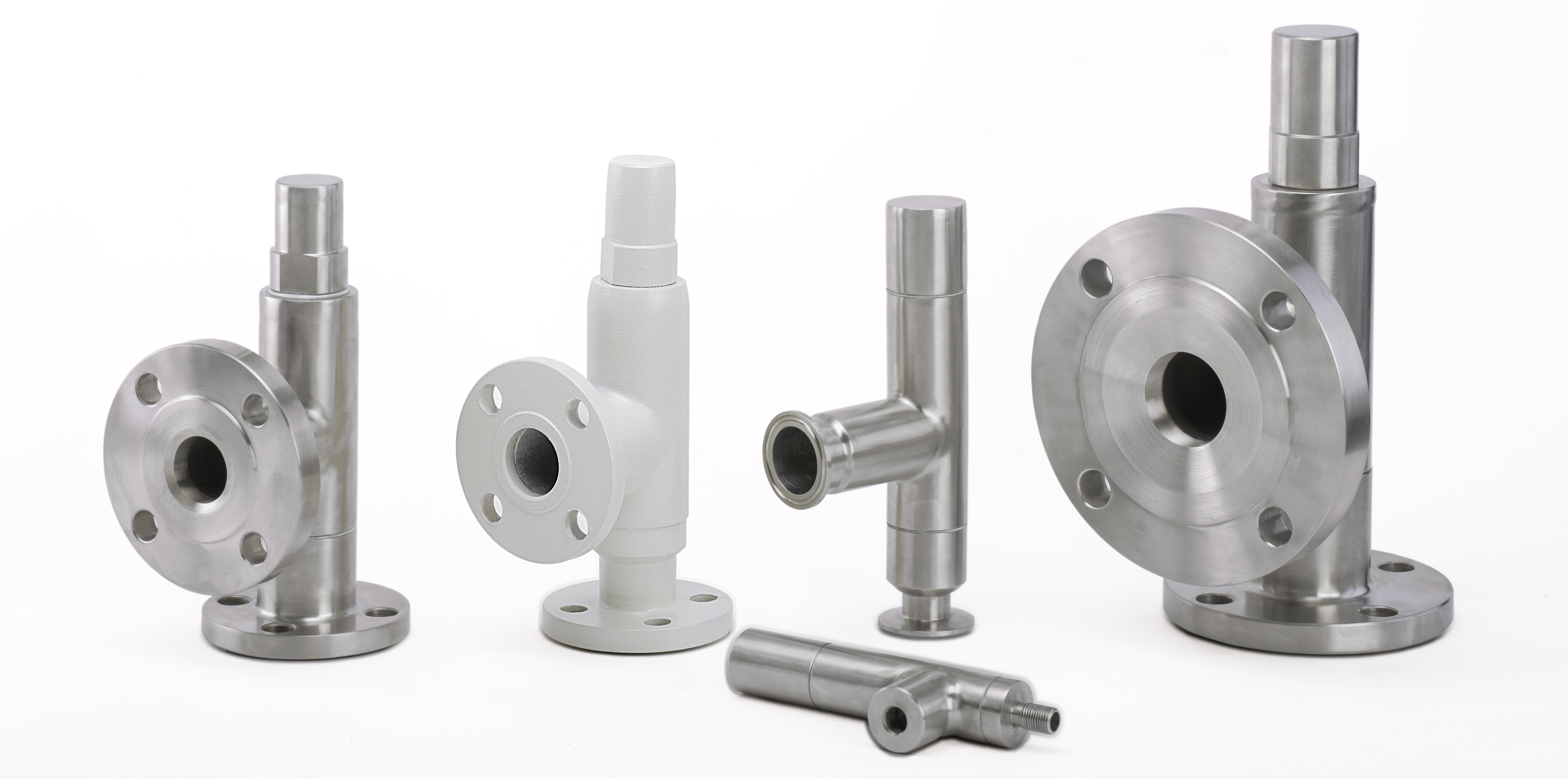
Our products are recognised globally for their exceptional quality and reliability, in recent years Seetru has worked hard to maximise the efficiency of our manufacturing processes, to ensure that we’re able to meet demands for supply and distribution. We now hold a large variety of safety valves in stock, allowing customers to purchase certain quantities from our website, and see them despatched on the same day.
Currently, Seetru offer atmospheric safety valves and pipped discharge safety valves in brass or stainless steel. The Seetru LGS® range of pressure relief valves (for liquid, steam, and gasses) are available in bronze construction, with open-lever and sealed-cap options. These valves can be fitted with PTFE or EPDM seals, with both types having the WRAS approval - for installation on public water supply systems.
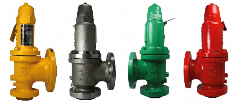
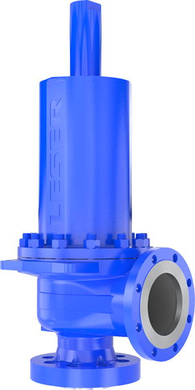
For customers who require larger valves with flanged connections, the LESER API safety valve offers ultimate protection against overpressure and it represents a safe solution for heavy duty applications, such as crude oil extraction, transportation, and processing (available from LESER UK Limited).
Given the huge success of our same day despatch service for safety valves, we are planning to make more valve types and models eligible for the quickest available delivery.
In addition to our same day despatch service for pressure relief devices, Seetru has also introduced a standardised three-day-despatch delivery service across our entire range of valves. Customers who choose to buy safety valves from Seetru will now benefit from the supply and distribution improvements we have put in place. The Seetru same-day-despatch, and three-day-despatch services for pressure relief valve delivery are available worldwide. We advise that customers purchase valves from our website where possible, however our sales team are always available to talk, should you wish to discuss your particular PSV needs in detail – we also recommend that you contact us if you’re looking for very large quantities of safety valves.
With our partner specifications archives, six on-site lathes, technical know-how and 35,000 in-stock valves, we’ve got your valve repairs covered. Valves are quickly repaired and set following exact specifications, and if they’re irreparable, chances are we’ve got a replacement in stock.
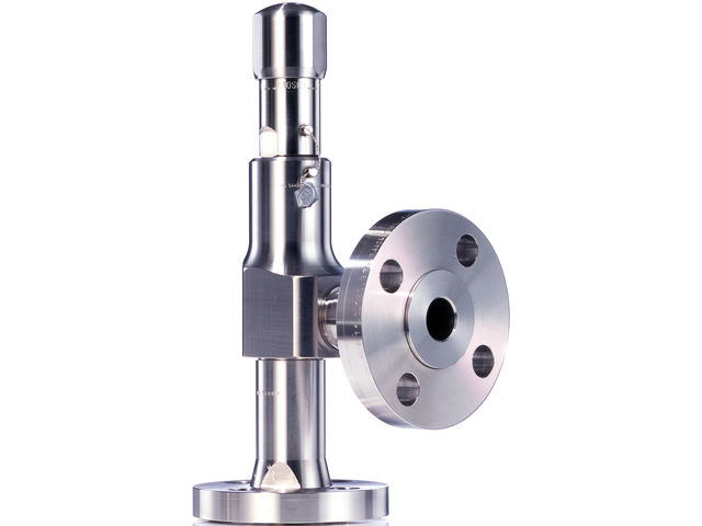
The TH series subsurface safety valves are tubing retrievable surface controlled subsurface safety valves used for high pressure environment. When installed, the safety valve is connected to the surface through the control line. The pressure from surface is transmitted through the control line, acts upon the piston of the safety valve and controls the opening and the closing of the safety valve. This series of products includes self-equalizing and non-equalizing types.

Surface-controlled subsurface safety valves (SCSSVs) are critical components of well completions, preventing uncontrolled flow in the case of catastrophic damage to wellhead equipment. Fail-safe closure must be certain to ensure proper security of the well. However, this is not the only function in which it must be reliable—the valve must remain open to produce the well. Schlumberger surface controlled subsurface safety valves exceed all ISO 10432 and API Spec 14A requirements for pressure integrity, leakage acceptance criteria, and slam closure.
Through decades of innovation and experience, Schlumberger safety valve flapper systems are proven robust and reliable. The multizone dynamic seal technology for hydraulic actuation of subsurface safety valves is a further improvement in reliability performance when compared with traditional seal systems in the industry.
The multizone seal technology is currently available in the GeoGuard high-performance deepwater safety valves, which is validated to API Spec 14A V1 and V1-H.
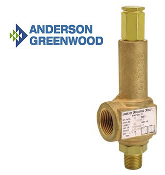
About AG’s 63B Safety ValveType 63B valves are direct spring-operated safety valves suitable for medium set pressure gas, vapor and liquid or gas thermal relief applications. Specific valve types are available for gas, vapor, liquid; gas or liquid thermal relief, steam, cryogenic and chemically active applications.
The 63B’s brass construction offers an economical valve for carbon dioxide, natural gas and general gas or vapor services. Yet, these relief valves use special internals and soft seals to provide optimum accurate performance.
About Seal Tightness Performance SpecsAll pressure relief valves are checked for seal leakage per procedures outlined in API 527. The following operating pressures will allow for bubble-tight seat sealing performance.

The primary purpose of a safety valve is to protect life, property and the environment. Safety valves are designed to open and release excess pressure from vessels or equipment and then close again.
The function of safety valves differs depending on the load or main type of the valve. The main types of safety valves are spring-loaded, weight-loaded and controlled safety valves.
Regardless of the type or load, safety valves are set to a specific set pressure at which the medium is discharged in a controlled manner, thus preventing overpressure of the equipment. In dependence of several parameters such as the contained medium, the set pressure is individual for each safety application.

The primary purpose of a pressure relief valve is to protect life, property and the environment. Pressure relief valves are designed to open and release excess pressure from vessels or equipment and then close again.
The function of pressure relief valves differs depending on the main type or loading principle of the valve. The main types of pressure relief valves are spring-loaded, weight-loaded and controlled pressure relief valves.
Regardless of the type or load, pressure relief valves are set to a specific set pressure at which the medium is discharged in a controlled manner, thus preventing overpressure of the equipment. In dependence of several parameters such as the contained medium, the set pressure is individual for each safety application.

blow-down systems and long pipework sections. The LESER Type 526 combines the requirements of the API standards and the ASME Code with the tried and tested service reliability of the LESER range.
Industry leading pressure and safety relief valve designs with over 140 years of technical and application expertise providing custom engineered solutions for O&G, Refining, Chemical, Petrochemical, Process and Power applications. Our designs meet global and local codes and standards (API 526; ASME Section I, IV & VIII; EN ISO 4126; PED & more). Gain insight into the performance of your pressure relief valves with wireless monitoring.
Providing you the best range of cast steel safety relief valves, open bonnet safety relief valve, stainless steel safety relief valve, flange end pressure relief valves, safety relief valve and pressure safety valve with effective & timely delivery.
The specification and purchase of valves in general can be a very complicated task depending on the time available that the instrumentation engineer has in a project and his own experience in developing this task. It starts with the fact that academic training, at least in Brazil, has very few courses aimed at industrial instrumentation and goes through the fact that each valve is, in essence, an engineering solution dedicated to an exclusive application. The probability of using a valve that has been specified and purchased incorrectly in another application is very low.
The need for use, selection, sizing, specification and, lastly, the purchase of valves usually arise within a multidisciplinary project; where several other very important instruments and equipments are allocating human resources that may even be working on parallel and independent projects and almost always with very lean HH. The result of this combination of factors is little time to sizing and specify a valve, be it for control or safety. This leads many engineers not to question why they adopt some requirements, especially when it is clear in the standard of the final customer that you have to follow it. When it comes to adopting API STD 526 in relation to the specification of safety valves, it is not very different.
Petrobras, which is one of the biggest motivating companies for the development of engineering in Brazil, has defined in its instrumentation standard N-1882D - Criteria for Elaboration of Instrumentation Projects; that safety valves must, among several requirements:Have the discharge orifices according to API STD 526;
API STD 526 requires the same above mentioned, so it´s clear that N-1882 was elaborated using as a basis, the API STD 526 guidelines and the adoption of this constructive standard proves to be practical since it meets at least four items of the N-1882D. This generated a culture within Brazilian engineering to adopt API STD 526 as a requirement in the design of the safety valve at least as a recommended practice.
The purpose of this short article is to present what the API 526 is about; why we must adopt and use this standard and also, because we must not follow blindly the requirements and guidelines of this standard. By reading this article you will be able to answer the following questions:What is the scope of API STD 526?
API STD 526 is a standard with the objective of guiding engineers, manufacturers, end users and buyers in the selection, specification, manufacturing standardization and purchase of safety valves. These valves can be operated by spring with or without balancing bellows (conventional or self-operated); or operated by a pilot valve (pilot-operated).
All valves according to API STD 526 must have inlet and outlet flanged connections in accordance with ASME B16.5. The pressure and temperature limits are defined in tables 3 to 16 for spring-operated valves and in tables 17 to 30 for pilot-operated valves. It is worth noting that, even though the flanges are in accordance with ASME B16.5; we must not adopt the pressure x temperature limits of this standard, because these limits are higher than those defined by API STD 526.
It refers to the possibility of exchanging the safety valve of one manufacturer for another without compromising the protection of the equipment or requiring greater interference in the equipment or pipeline. This is possible for a few reasons.
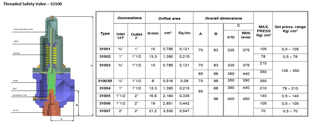
The first one is the standardization of the discharge orifice areas, which defines maximum flow capacity values very close even for different manufacturers. The orifices are designated by letters that start in "D" and go up to "T". If one manufacturer “A” presents as a protection solution for an equipment, a safety valve 1D2 (one inch for inlet connection, orifice D and two inches for outlet connection) and manufacturer “B” presents another valve 1D2; we can say that “A” and “B” have interchangeable solutions.
Another reason that allows interchangeability is that API STD 526 also defines the distance from the face of the input flange to the center of the output flange; the distance between the face of the outlet flange and the center of the inlet flange and the connection patterns of the inlet and outlet flanges including the diameters and pressure classes themselves. In this way, it is possible to replace one valve with another with practically zero impacts on the piping and on existing equipment. Example: To replace a 1D2 valve from manufacturer A with a 1D2 valve from manufacturer B, there is no need to change flanges or pipe rearrangements.
Interchangeability also brings the benefit to the end user not being dependent on a single supplier that could, for different reasons, stop its commercial operations in a country, complicating or stopping the supply of valves or spare parts.
It is worth noting that, different manufacturers supplying interchangeable valves for the same application; may have different maximum certified discharge flow rates. The discharge orifice area calculations for API STD 526 valves are according to API STD 520 Part 1, but these are preliminary calculations that use recommended discharge coefficient (Kd) in the equations described in the items 5.6 to 5.10 of API STD 520 Part 1 as a starting point for making calculations possible. Each manufacturer has its certified discharge coefficient. Fortunately, most manufacturers have a certified discharge coefficient lower than that determined by the standard, which results in an area larger than the effective one defined by API STD 526. However, as not all manufacturers are; it is prudent then, when purchasing the valve, the instrumentation engineer requires the sizing report with the value of the maximum discharge flow certified from the manufacturer that is selling the solution.
API STD 526 defines the materials that must be used in the main parts of the safety valve such as body, bonnet, spring, flange and nozzle depending on the temperature and pressure that the valve is subjected at the opening moment.
Materials that are normally used in the manufacture of valves of all types such as carbon steel ASME SA-216 Gr. WCB and stainless steel ASME SA-351 Gr. CF8M are placed as minimum requirements for safety valves to be used in certain parts of the valve like body and the bonnet. This guarantees valves with similar performance, weight, mechanical strength and corrosion resistance from different manufacturers.
The requirements above does not restrain any supplier from adopte another material to produce his valve, that for many reasons, may be economically more attractive, since, it has higher pressure x temperature limits than those materials standardized by API STD 526. After all, the Instrumentation Engineer has to evaluate any material used regarding chemical compatibility with the process fluid.
API STD 526 also establishes that valves manufactured in accordance with this standard, must also comply with API STD 527. This last standard deals with the seat lekage while the valve is closed; or in other words; while the pressure scenario in the vessel or pipe is normal. All valves from all suppliers that will be involved in a purchasing process will have the same performance related to the seat leakage.
Although API STD 526 standardizes important parts of the valve, it does not defines all parts. It is still possible to find opportunities for innovation to deliver to the user, the best cost-benefit solution without neglecting the pressurized system protection that is so important.
The scope of the standard makes it clear that API STD 526 is a standard that should be used to purchase a safety and/or relief valve and defines minimum criteria to be met in order to be successful.
By standardizing all these criteria and requiring all suppliers of safety valves to produce a large amount of valves in accordance with API STD 526, a favorable scenario for bidding is created, cause the solutions become very similar. This way, the manufacturers will compete to get the lowest price.
It also facilitates the analysis of the engineer who always spends a good HH with the technical advice of the valve supply proposals. With a wide standardization, the time and cost necessary to evaluate, adjust and approve technical solutions is reduced. The standard itself presents in its appendix A, a data sheet containing the minimum information that must be specified in order to allow a technical and commercial consultation to manufacturers for the supply of spring and pilot operated safety valves. Annex B shows the minimum information that must appear on the nameplate.
Standardization allows the manufacture and strategic stock of nozzles, flanges, bonnets, bellows, caps and other components. In this way, it´s possible to assemble, test and ship the safety valve in the shortest possible time. It is not always necessary to cast parts or make more complicated adjustments that are not foreseen in the standard.
For small equipments such as pump sealing systems, pump recycles, air tanks for control valves, pig receivers and launchers, among others, that have a small volume of fluid to be relieved to normalize their pressure; using compact small valves is advantageous as they are easier to install. Usually threaded with ¾ ”NPT inlet and 1” NPT outlet, they are cheaper and have a discharge orifices with areas smallers than the D equivalent of API STD 526, which avoids making use of a oversized valve just to meet a construction standard. Oversized pressure safety valve can lead the valve to chattering, as the flow may be too small to be able to open the safety valve at once and the disc will again hit the inlet nozzle seat repeatedly, damaging the assembly and compromising the tightness or worse, compromising performance expected at the time of opening.
With simple design and with fewer parts, the safety valves for thermal relief (or compact), allows a good cost reduction. Since others legal requirements such as the National Board flow certificate and / or the ASME authorization certificate for the manufacturing site be part of the supply documentation; there is no greater cause for concern for the end user.
If the user still wants to replace an existing safety valve that does not comply with API STD 526, with another one according to API STD 526, he will have to evaluate whether the installation follows the recommendations of API RP 520 Pt 2. This evaluation that already has a cost, can lead to the conclusion that the pipes and connections need to be replaced and / or rearranged which would mean even more costs.
If costs is always an important factor in the projects; we can also verify that a valve according to API STD 526 does not always present the best cost benefit for the customer.
There are some good reasons for large companies to adopt API STD 526, if not as a requirement, at least as a recommended practice. All the criteria to be followed and the advantages presented, make API STD 526 kind of a guide to acquire a safety valve with the best cost benefit. It should not be forgotten, however, that the ultimate purpose of a safety valve is to open to guarantee the relief of a system that is in a pressurization scenario and to close when the situation is normalized. The construction according to API STD 526 does not replace the correct sizing and the need for ASME authorization certificates for the factory and the National Board certificate regarding the flow capacity of the tested model for the manufactured site.
**Update to this article, June 7, 2022 : If you found this article helpful, here is a link to another article I recently found that does a nice job explaining the topic: ENGINEERS BEWARE: API vs ASME Relief Valve Orifice Size – Petro Chem Engineering (petrochemengg.com)
NOTE: this article is written to an audience that is familiar with PSVs, PSV sizing, and API and ASME standards at a basic level. I initially wrote this article in early 2017, and due to some great input and questions made significant revisions to increase clarity in mid-2018. I hope it is helpful to you, please send me a message with any comments/questions!
If you"ve ever sized/selected a Pressure Safety-Relief Valve (PSV) using vendor sizing programs or good-old hand calculations, you"ve probably run into a very strange anomaly: Why does a PSV orifice size change between American Petroleum Institute (API) and American Society of Mechanical Engineers (ASME) data sets? What is an "effective" orifice area? How do I know which standard to use when selecting a PSV?
Usually, this issue is one of curiosity and doesn"t affect the end result of what valve is chosen. Common practice is to default to API sizing equations and parameters, and only use ASME data sets for situations outside of the API letter-designations. But what if I told you that approach is likely causing you to oversize about 10% of your PSVs and their respective piping systems?
Most of the time simply using API data sets is fine. And I should note that this is a conservative approach, so you won’t make a mistake doing this. But did you know that PSVs are certified to ASME capacities, not API? And did you know those ASME capacities are nearly always higher than the API ones? I’m guessing you don’t, because there are very few resources available that speak to this topic. I’ve found it common for engineers to understand API 520 quite well, but have a very limited working knowledge of how the ASME BPVC comes into play.
Too often, we leave that third part out of the process, and simply calculate relief loads and select valves using API techniques, without ever checking our selection against certified ASME data. Proper application of these standards is the first key point of this article:
Initial sizing and valve selection is done using API equations, and final valve selection and certification is done using ASME-certified coefficients and capacities.
When sizing a PSV, the sizing equations are always API 520. When a PSV is certified, it is always certified to ASME BPVC (whether one “selects” ASME certification or not!) It"s important to remember that the ASME BPVC is the "code", the standard to which we must design. API 520/526 are "recommended practices" which were developed to give engineers a tool to meet the ASME requirements. Another way to look at it: ASME BPVC sets the goal, API 520/526 provide the instructions, and ASME has the final say.
The BPVC is an enormous code, and not reviewed in detail here. On the subject of PSVs, it basically says that a PSV must be capable of relieving the required load, and it must be tested in a specific manner to be certified to do so. If a valve is tested per the specific directions in the BPVC, it will be ASME certified and receive an ASME UV stamp.
The first thing API does is attempt to standardize physical PSV sizes and design, and it does so in API RP 526, which is targeted at PSV manufacturers. API provides pre-defined valve sizes, with letter designations D through T (API 526). It also defines other details directed toward valve manufacturers (such as temperature ratings). All of this is intended as minimum design standards, and manufacturers are free to exceed these parameters as they wish.
The second thing API does is provide standardized equations and parameters to use when trying to figure out just what size of a PSV one needs for a particular scenario. The equations account for design parameters that ASME doesn"t speak to, such as specific fluid properties, backpressures, critical flow, two-phase flow, and many other aspects of fluid dynamics that will affect the ability of a particular valve to relieve a required load.
API sizing equations are by nature theoretical, standardized, and use default or "dummy" values for several sizing parameters that may or may not reflect the actual values for any specific valve.
API RP 520 very clearly talks about this, and emphasizes that the intended use of its equations is to determine a preliminary valve size, which should be verified with actual data. API intends PSV sizing to be a two-step process, but we are often unaware of this because we (gasp) don’t read the full standard, and/or rely solely on vendor sizing software that hides the iteration from us. See API 520, part 1, section 5.2 for further explanation.
When valves are built, they are built to the API RP 526 standard, however, as one might imagine, when valves are actually tested and certified, the results don’t match up identically to the theoretical values that were calculated. This is where API and ASME intersect; we switch from calculations (API) which were used as a basis to design the valve, to actual empirical data (ASME) to certify the valve. When a valve manufacturer gets the UV code stamp that certifies the valve orifice size and capacity, it is based on actual test results, not API sizing standards. And ASME (which came first) does not have tiered letter designations. The typical D, E, F, etc. sizes we refer to are strictly an API tool, and ASME’s capacity certifications are completely independent of them!
3. A third-party Engineer (you), trying to select a PSV, runs a sizing calculation using API 520 equations on ABC Valve Company"s sizing software, gets a result that requires 4.66in2 to relieve the load, and is now thoroughly confused on what size valve to select.
If one selects the API data set on the sizing software in this example, it will automatically eliminate N-orifice valves as an option, and bump the user up to a P-orifice. However, if one simply selects the ASME data set, the N-orifice valve magically reappears as an option. How can this be? Will the N-orifice work or not?
The short answer is yes, it is certified to an actual area of 4.90in2. So the “N” orifice for this specific PSV will work, and is certified to do so, in this application. Remember: use API to get you close, and ASME to confirm the final answer.
Digest that for a moment. If you’ve sized and purchased more than a dozen PSVs, chances are you have inadvertently selected a PSV a full size larger than you needed to, in a situation much like our example, simply because you chose a PSV based on its API “rating” rather than its real, certified, stamped ASME rating. If that was a small valve, impact was probably nil. But what if this happened on a valve that resulted in selecting a 8x10 PSV when you could have used a 6x8?
If you’re like me, that answer isn’t very satisfying. Why on earth is this so confusing? How can you simply hit a button on the sizing program and a different size of valve is suddenly acceptable? The key lies how the main coefficient of discharge, Kd, is handled, and how capacities are determined.
There are several K values used in API calculations, all of which have generic values defined in API 520 that can be used for preliminary sizing. These are the numbers used in initial sizing calculations to get us close, then (if we do this correctly) replaced with the actual/tested/empirical/ASME values when we get a certified valve. Remember, anytime you hear “certified” or “stamped”, think ASME.
Let’s take the numbers from the example above, which came from an attempt to size a valve for liquid relief. API says to use a value of Kd=0.65 for liquid relief. If one uses the API data set on the vendor software, then the calculation stops here, and you get a required area of 4.66in2. When you select a valve, you’re comparing that to the API effective (actual) area of an N orifice, which is 4.34 in2, which is obviously too small and you’d logically step up to a P orifice. However….
Remember that the API N-orifice area is just the benchmark, a minimum requirement, and may or may not (most likely not) reflect the actual area of a real-life PSV. Once a valve is selected, all of those K values and capacities should be replaced with actual ASME-certified K values, also determined by testing, that are specific to each valve model, and the calculations performed again.
Normally, ASME-certified K-values are smaller than the API dummy values, driving up the required orifice area. So valve manufacturers have to over-design their valves to make up for it, resulting in ASME-certified areas and capacities that typically exceed the benchmark API ones. The end result of all this?
It (almost) all boils down to one sneaky little sentence in the ASME BPVC which mandates a 10% safety factor on the empirically-determined Kd that “de-rates” the valve (see ASME BPVC Section VIII, UG-131.e.2). This tidbit seems to be a little-known fact that is key to proper PSV sizing and selection, because as engineers we often pile safety factors upon each other and oversize our equipment. I cannot highlight this enough:
I mentioned above that ASME K values are nearly always lower than API values, due to this 10% de-rating. The PSV in our example scenario has a determined Kd of 0.73, which is adjusted down by 10% for a final AMSE Kd of 0.66, slightly higher than the dummy API value (that just means that this particular valve proved it could do about 11% better than the minimum theoretical flow calculated by API when it was tested). So, for our valve in question, the Required ASME area is slightly less than the API area. This is atypical, but not unheard of, and again points to the importance of checking the ASME ratings of any valve you select, and comparing against the API benchmarks.
When you choose to use the ASME data on a specific valve, it’s not just the Kd sizing factor that changes; the actual orifice area and therefore the capacity of the valve also adjusts to empirical, certified values. You can generally expect both values to increase over the API values.
Why is this? Simply that any given real-world valve is usually over-designed so that it will meet and exceed the required minimum capacity of its corresponding API size. What a simple concept, but so often overlooked by engineers!
Back to our example scenario: even though the ASME Kd, and hence required area, adjustment had a negligible effect, the actual ASME orifice area, and hence capacity, is significantly higher than the listed API area and capacity for an N-orifice. Below is a summary:API N Orifice: 4.340 in2
*Note: this is data from a real case; the specific PSV make/model is omitted. Did you catch the result? The actual, certified capacity of this valve is nearly 13% higher than the generic N-orifice valve, and that includes its 10% safety factor!
With this adjusted orifice area, we can compare to the ASME certified area (which is always going to be larger than the API area), and we have our final answer for the valve size. Often this will not result in a different choice of valve, but sometimes, as in the example case, it will allow us to use a valve with an API letter designation that did not appear large enough based on its API effective area. This can save time and money for our plants by preventing over-sizing valves, leading to smaller piping systems to support them. And remember, the ASME values are empirical and have a 10% safety factor built in, so we don’t need to worry about cutting the design too close; the conservatism is already built in to the method. We can choose the Brand X N-orifice valve and sleep well at night!
Avoid simply defaulting to the API data set for the final “rating” or data sheet when selecting a PSV. Use API sizing calculations as they are intended: for preliminary valve selection. Then switch to the ASME data set. This will often (but not always, remember, it"s valve-specific) result in two differences:
1. An actual orifice area that is greater than the standard API letter-designated orifice area. This is ok; it just means the PSV selected performs slightly better, or is slightly larger, than the minimum design conditions for its API letter designation.
2. A required orifice area that is greater than the one calculated by API. This is also ok, and is usually due to the 10% de-rating on Kd that ASME requires.
ASME section VIII “UV” stamp | PED “CE” mark | DOT, API | Marine IGC, ABS, BV, DNV-GL, LR | ISO 9001:2015 | Canadian CRN Approval (all provinces/territories)


 8613371530291