
burst safety valve free sample

Changes in the law and ever stricter environmental regulations are forcing plant owners to reduce their emission levels. This also applies to pressure relief devices such as safety valves. To avoid having to use far more expensive valves – which are often difficult to retrofit – it is a good idea to install a rupture disc upstream of the safety valve.
The first step towards fulfilling the regulations was to try and find better safety valves, which were simple to build into the design of new valves. However, substantial investments were necessary to upgrade the older designs of existing plants with newer ones – not an economical choice in the majority of cases. Even with new plants, there was a significant increase in safety valve costs in the endeavour to meet the lower emission levels required for certification and permits, to be allowed to start up a plant or continue operating it.
Although the capabilities of safety valves were expanded considerably, they were still not able to comply with the requirements envisaged for future zero targets. In fact, it was believed that they never would do and so an alternative solution was needed.
Rupture discs have been around for decades but have always been seen as a second-choice alternative for overpressure compared to safety valves – the poor relation of the safety valve industry, as it were, a title they do not deserve. This lack of understanding of rupture discs continues to this day. Discs are a “problem”: they open and let the pressure out, when in fact that is exactly what they are designed to do. Many operators remain blissfully unaware that when the disc performs correctly, this is not the problem but the solution.
So how do rupture discs help safety valves perform better in use? Well, when it comes to isolation, they partner safety valves and deliver the superior performance needed to realise zero emissions which a stand-alone safety valve cannot provide. Although safety valves can achieve good performance levels on their own, one hundred percent isolation and better operational stability require the use of rupture discs. For several years now, rupture discs have been regularly installed upstream of safety valves. Operators are starting to appreciate that a properly engineered rupture disc will help lower their operating costs and increase plant uptime. The belief that this arrangement adds more cost to a project has been proven to be false; in fact, the opposite is true and the costs actually come down.
Let us take a typical installation where the safety valve faces a process condition with a high concentration of corrosive materials, elevated temperatures and an operating pressure close to the valve’s set pressure. The safety valve’s limits are put to the test, leading to poor performance below the expected levels for operational stability and leakproofness. High maintenance costs are incurred to keep the valve as close as possible to the original specs, along with increased downtime for routine valve servicing and/or repairs and higher manpower costs to handle the work.
The solution suggested by safety valve manufacturers is a valve with a higher specification, more exotic materials with higher capex costs and more expensive spares for maintaining the valves. In an average petrochemical plant with several hundred safety valves, this capex translates into a dramatic increase in valve inventory costs.
Rupture discs fitted upstream of the safety valve, in a material that will isolate and withstand the process conditions, let the plant owner install lower grade materials in the valve while still meeting all the design requirements, though with a significant reduction in the safety valve capex.
The costs for the rupture disc and holder are negligible compared to the capex for an exotic or higher-specification safety valve. If account is also taken of the lower expenditure on maintenance, the disc and holder are free of charge. In fact, this is a win-win path with more production uptime, less emissions, greater safety, lower overall maintenance costs and reduced inventory.
Yet, we still see safety valves with an upstream rupture disc failing, needing maintenance and stopping production or causing safety issues. So what went wrong? Remember that a safety valve also has an outlet. In many cases, this outlet is not a separate line to discharge but is manifolded together with other parts of the plant, allowing process gases or vapour to enter it and provoke safety valve failures. This is something easily eliminated by a downstream rupture disc, which prevents any process gases from entering the safety valve on the outlet side. The rupture disc will also block any back pressure attempting to enter the safety valve and eliminate such concerns during valve selection.
With burst sensors installed both upstream and downstream, rupture discs can be monitored and connected back to the control room for system reporting across the plant, so that operators know instantly which valves and discs are in a green or red state.
The rupture disc manufacturer can collaborate with design and process engineers to select the discs giving the best possible safety and isolation performance. Unfortunately, this is still a rarity and is a factor in the rupture disc being blamed for poor performance when all it is actually doing is what it was designed to do, namely be the most important safety device in the plant – the only fail-safe device that always opens when faced with an overpressure situation.
Rembe was approached by a refinery to help overcome serious issues with its safety valves due to process conditions attacking the metal structure. The requirement was to enable the plant to be operated for three years without having to remove the safety valves for servicing and recertification except in an emergency. When the safety valves were removed during a scheduled shutdown, several of them were found to have broken or cracked springs while others were corroded to failure point. Bellows were corroded and broken. Several safety valves were so badly affected that the disc and nozzle were corroded solidly together and the valve was unable to open. This raised major safety concerns that the plant could no longer meet its three-year maintenance-free plan and it was decided to return to the old test method of regular safety valve removal and replacement.
An analysis carried out in conjunction with Rembe showed that aggressive process gases were present both upstream and downstream of the valves, and that isolation with rupture discs in a suitable material would offer the best protection. What’s more, the user would stand a more realistic chance of meeting the three-year target, with the ultimate goal of extending this to five years.
In addition, the use of KUB V rupture discs allows for in-situ lift testing of the safety valves on site during the three-year period, to ensure that they are still operational. As a further benefit, the costs are lower because the Rembe rupture discs can be removed, inspected and reused, and are still in serviceable condition.

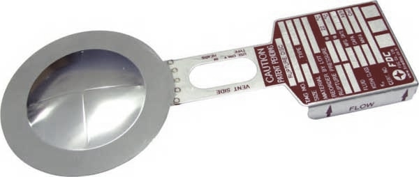
This assembly consists of a thin, circular membrane usually made of metal, plastic, or graphite that is firmly clamped in a disk holder. When the process reaches the bursting pressure of the disk, the disk ruptures and releases the pressure.
Rupture disks are commonly used in series (upstream) with a Relief valve to prevent corrosive fluids from contacting the metal parts of the valve. In addition, this combination is a reclosing system.
A rupture disk is a sensitive relief device designed to rupture at a pre-determined pressure and temperature. It is a means of providing protection for personnel and equipment. As such, it must be a fail-safe device. Rupture disks are used where instantaneous and full opening of a pressure relief device is required. These devices are also utilized where "zero" leak-age is required of a relief device. These devices can also be used in series as "quick opening" valves.
Rupture disks may be used either in primary relief, in secondary relief, in series with a Relief valve, or for other functions like "quick opening" valves.
When used in a secondary relief capacity, the rupture disk provides a backup vent to a primary relief device, usually a Relief valve. Its purpose here is usually to provide additional protection against an unlikely but possible major event that would exceed the capacity of the primary relief device.
When used in series with a pressure Relief valve, the rupture disk is usually installed upstream of the valve. The disk will protect the valve from process media that can corrode or plug it. The disk can also act as a seal, preventing any leakage through the valve unless the disk is ruptured.
The space between the rupture disk and the pressure Relief valve must have a pressure gauge, try cock, free vent, or suitable telltale indicator. The normal configuration is an excess flow valve in combination with a pressure gauge. This arrangement is to eliminate the possibility of, or facilitate the detection of, a backpressure build up. Because a disk responds to the differential pressure across it, it will not burst at its rated pressure if a back pressure is allowed to exist in this cavity.
A low-pressure rupture disk can be used on the downstream side of a Relief valve that discharges into a common manifold to prevent exposure of the valve to process or corrosive media discharging through the common manifold. The space between the Relief valve outlet and the rupture disk must be vented to prevent the accumulation of pressure, which could adversely affect the Relief valve set pressure. An excess flow valve will suffice for this feature.
Due to the small inertia characteristics of a rupture disk, the opening time, i.e., from a closed and sealed condition to a full open condition, is less than one half of one millisecond (0.0005 sec.). This characteristic allows a rupture disk to function as a "quick opening" valve.

The primary purpose of a safety valve is to protect life, property and the environment. Safety valves are designed to open and release excess pressure from vessels or equipment and then close again.
The function of safety valves differs depending on the load or main type of the valve. The main types of safety valves are spring-loaded, weight-loaded and controlled safety valves.
Regardless of the type or load, safety valves are set to a specific set pressure at which the medium is discharged in a controlled manner, thus preventing overpressure of the equipment. In dependence of several parameters such as the contained medium, the set pressure is individual for each safety application.

Usually, the rupture disc is installed upstream the safety valve. However, there are also applications where rupture discs can be installed downstream a safety valve, whereas a rupture disc-safety valve-rupture disc arrangement is also possible in accordance with AD 2000 Merkblatt. Bursting pressure of rupture disc is equal to the set pressure of the safety valve.
Based on ISO 4126-3 standard, a length not exceeding five (5) times the nominal size of the inlet piping will have to exist between the rupture disc and the safety valve inlet.
- A space monitoring device, typically a pressure indicator, must be provided between the rupture disc and the safety valve so as to have a clear indication whether the disc has ruptured but also to ensure that the space between the 2 devices is properly ventilated: without ventilation, back pressure could increase and this could change the set pressure of the rupture disc.
- Inlet lines and rupture discs upstread safety valves shall be designed in such a way that the pressure drop in the inlet line to the safety valve must not exceed 3% of the set pressure.
- For rupture discs installed upstream of safety valves, non-fragmenting rupture elements are recommended to be used so as not to damage the safety valve downstream.

Safety valves and pressure relief valves are crucial for one main reason: safety. This means safety for the plant and equipment as well as safety for plant personnel and the surrounding environment.
Safety valves and pressure relief valves protect vessels, piping systems, and equipment from overpressure, which, if unchecked, can not only damage a system but potentially cause an explosion. Because these valves play such an important role, it’s absolutely essential that the right valve is used every time.
The valve size must correspond to the size of the inlet and discharge piping. The National Board specifies that the both the inlet piping and the discharge piping connected to the valve must be at least as large as the inlet/discharge opening on the valve itself.
The connection types are also important. For example, is the connection male or female? Flanged? All of these factors help determine which valve to use.
The set pressure of the valve must not exceed the maximum allowable working pressure (MAWP) of the boiler or other vessel. What this means is that the valve must open at or below the MAWP of the equipment. In turn, the MAWP of the equipment should be at least 10% greater than the highest expected operating pressure under normal circumstances.
Temperature affects the volume and viscosity of the gas or liquid flowing through the system. Temperature also helps determine the ideal material of construction for the valve. For example, steel valves can handle higher operating temperatures than valves made of either bronze or iron. Both the operating and the relieving temperature must be taken into account.
Back pressure, which may be constant or variable, is pressure on the outlet side of the pressure relief valve as a result of the pressure in the discharge system. It can affect the set pressure of the upstream valve and cause it to pop open repeatedly, which can damage the valve.
For installations with variable back pressure, valves should be selected so that the back pressure doesn’t exceed 10% of the valve set pressure. For installations with high levels of constant back pressure, a bellows-sealed valve or pilot-operated valve may be required.
Different types of service (steam, air, gas, etc.) require different valves. In addition, the valve material of construction needs to be appropriate for the service. For example, valves made of stainless steel are preferable for corrosive media.
Safety valves and relief valves must be able to relieve pressure at a certain capacity. The required capacity is determined by several factors including the geometry of the valve, the temperature of the media, and the relief discharge area.
These are just the basic factors that must be considered when selecting and sizing safety valves and relief valves. You must also consider the physical dimensions of the equipment and the plant, as well as other factors related to the environment in which the valve will operate.
A rupture disc is a non-re-closing pressure relief device that protects a pressure vessel, equipment or process piping system from over-pressurization or potentially damaging vacuum conditions. Rupture discs are, next to pressure safety valves, the most commonly used pressure protection devices in industrial plants. A rupture disc has a one-time-use membrane that fails at a predetermined differential pressure, either positive or vacuum. Rupture discs provide instant response to over-pressurization or under-pressurization in process piping system, but once the disc has ruptured it will not reseal. Major advantages of the application of rupture discs compared to using pressure relief valves include fail-safe performance, leak proof and most economical (cost-wise).
Rupture disc can be used for isolating the high-cost valves from the process in case of over-pressurization, thereby saving on valve maintenance and replacement.
Rupture discs can be used to specifically protect installations against unacceptably high pressures or can be designed to act as one-time valves or triggering devices to initiate with high reliability and speed a sequence of actions required.
In the case of over-pressurization, if the pressure safety valve fails to operate or unable to relieve excess pressure fast enough, the rupture disc will come into action and burst controlling the pressure.
Usually pressure safety valves tend to leak more after being triggered for the first time. Rupture discs can be used upstream of the pressure safety valve to ensure a perfect leak proof seal.
In case of corrosive, adhesive, polymerizing or viscous fluid in the process piping system, rupture disc in upstream helps in safeguarding the functionality and reliability of pressure safety valves. Due to this reason less expensive pressure safety valve material can be used with corrosive fluid. Also It is cheaper to replace a rupture disc than a pressure safety valve.
Pressure safety valves can be tested without removing from the process piping system. To do this, the space between the rupture disc and the valve stroke is pressurized. As the rupture disc have almost double back pressure resistance, the rupture disc remains undamaged while the safety valve is being inspected.
The combination of a rupture disc prior to a safety valve is becoming more and more important. Rupture discs provide protection for safety valves while at the same time saving money on maintenance and re-engineering.
Reverse acting rupture discs are installed with the domed side of the rupture disc facing the process system. As the burst pressure rating of the disc is reached, the compression loading on the rupture disc causes it to reverse and open disk by a predetermined scoring pattern. It is also called as Compression loaded type disk.

In any complex piping system, one of the most serious scenarios considered during a safety or HAZOP study is over-pressurization. If the pressure in the system reaches a high enough pressure, rupture can occur, leading to expensive repairs, significant system downtime, and even loss of life. In most cases, proper use of relief valves can mitigate or avoid pressure-induced rupture. Fortunately, AFT software can be used to easily and accurately model relief valves in a variety of scenarios, assisting engineers in designing safe and reliable systems.
All three major AFT products – AFT Fathom, AFT Arrow, and AFT Impulse – are capable of modeling relief valves for the conditions each are designed for. AFT Fathom and AFT Arrow can help show if the steady state scenario will ever reach the relief valve set point, and how that system will operate after the relief valve is opened. AFT Impulse can help understand how the valve will behave during both steady state and transient operation, and how the system as a whole will respond to various transient events.
To model relief valves, AFT Impulse provides four valve profile templates plus a general profile option that allows the user to specify a unique valve design, and are outlined in red in Figure 1 below. These four profiles include: Passive: the valve opens and closes based on pressure forces. Typical passive valves are constructed using a spring to keep the valve closed below the set point and to close it as the pressure is lowered.
Pilot Operated: the valve opens and closes based on pressure forces. Typical Pilot Operated Relief Valves (PORVs) use a hydraulic fluid on the back side of the valve to hold the valve closed. This fluid can either be a separate system or connected to a remote location in the network.
Rupture Disk: the valve opens at a set pressure and does not close. Rupture disks are often used when quick response is needed to avert an infrequent but serious over-pressurization scenario.
Surge Anticipator: the valve opens and closes based on pressure forces. Typical surge anticipating valves are operated similarly to a remote sensing pilot operated valve, with the system working to dampen pressure waves traveling through a system.
The General Profile option allows the user to create their own valve, allowing it to open and close instantaneously, along a defined time-Cv path, or based on pressure forces. With this General Profile option, when the user selects "Time" for the opening or closing profile, they are then able to go to the Transient tab, where they can enter information to define that transient profile.
Below the Profiles section, the Valve Setpoints section allows the user to define operating points of the valve. The Set Pressure defines the pressure at which the valve begins to open, the Overpressure defines when the valve is fully open, and the Blowdown Pressure defines when the valve closes.
Furthermore, all types of relief valves modeled in AFT Impulse can be modeled as either hydraulically balanced (with constant backpressure) or not. When the valve is balanced, the valve mechanism is independent of downstream pressure, and the set points can be defined based on the actual upstream pressure. When the valve is not balanced, the backpressure on the valve is not constant, and the set points are based on pressure differential with the downstream conditions.
The rest of the input for relief valves in AFT Impulse is similar to any other valve junction in the software. Users can input loss modeling information for their valve, allowing AFT Impulse to accurately determine flow through the relief valve while it is open. They can also add in Design Alerts, notifying the engineer if any set of events happens to the valve including it opening or reaching a specific pressure or flow rate.
With these options, virtually any relief valve design can be modeled during transient events, allowing their effects on the rest of the system to be accurately determined. Let"s take a look at how different relief valves affect a system in AFT Impulse.
The system we"ll look at, depicted in Figure 2 above, has pump J2 trip with inertia 5 seconds into the simulation, while valve J4 closes linearly over the first 2 seconds of the simulation. Notice that pipe P2 is 10,000 feet long, meaning the pressure wave generated in the system takes some time to travel back and forth, allowing us to see pressure surges relatively spaced out.
First, let"s look at how the system operates with and without a relief valve. Figure 3a below shows the inputs used for the relief valve in the system, while Figure 3b plots the static pressure just upstream from valve J4 over a 30 second period. As the graph shows, not including a relief valve in the system could subject the valve to serious forces, while a relief valve and surge tank system is able to keep the pressure close to the normal operating conditions.
Next, let"s look at how different types of relief valves affect the system. Figure 4 below, compares two different relief valves: a rupture disk set to 300 psia and the same passive relief valve shown in Figure 3a. As the graph shows, both systems rapidly pressurize and open after only a few seconds. However, because the system with a rupture disk releases most of the system pressure when the system first passes 300 psia, the pressure quickly drops towards the system pressure and experiences substantially reduced pressure variations at later times.
As evidenced by these two examples, modeling relief valves in AFT Impulse gives engineers the ability to analyze and understand which types and designs are best for their system. It allows them to understand how a relief valve will perform in the context of potential over-pressure events, during system design, and before those events happen during operation.
This discussion of relief valve design gives a good starting point for effectively and accurately creating models in all AFT software products. As with any aspect of system modeling, this topic has far more nuance and complexity than discussed here. For further help with relief valves – or any other topic – reach out to AFT"s support group at This email address is being protected from spambots. You need JavaScript enabled to view it..

Safety is of the utmost importance when dealing with pressure relief valves. The valve is designed to limit system pressure, and it is critical that they remain in working order to prevent an explosion. Explosions have caused far too much damage in companies over the years, and though pressurized tanks and vessels are equipped with pressure relief vales to enhance safety, they can fail and result in disaster.
That’s also why knowing the correct way to test the valves is important. Ongoing maintenance and periodic testing of pressurized tanks and vessels and their pressure relief valves keeps them in working order and keep employees and their work environments safe. Pressure relief valves must be in good condition in order to automatically lower tank and vessel pressure; working valves open slowly when the pressure gets high enough to exceed the pressure threshold and then closes slowly until the unit reaches the low, safe threshold. To ensure the pressure relief valve is in good working condition, employees must follow best practices for testing them including:
If you consider testing pressure relief valves a maintenance task, you’ll be more likely to carry out regular testing and ensure the safety of your organization and the longevity of your
It’s important to note, however, that the American Society of Mechanical Engineers (ASME) and National Board Inspection Code (NBIC), as well as state and local jurisdictions, may set requirements for testing frequency. Companies are responsible for checking with these organizations to become familiar with the testing requirements. Consider the following NBIC recommendations on the frequency for testing relief valves:
High-temperature hot water boilers (greater than 160 psi and/or 250 degrees Fahrenheit) – pressure test annually to verify nameplate set pressure. For safety reasons, removal and testing on a test bench is recommended
When testing the pressure relief valve, raise and lower the test lever several times. The lever will come away from the brass stem and allow hot water to come out of the end of the drainpipe. The water should flow through the pipe, and then you should turn down the pressure to stop the leak, replace the lever, and then increase the pressure.
One of the most common problems you can address with regular testing is the buildup of mineral salt, rust, and corrosion. When buildup occurs, the valve will become non-operational; the result can be an explosion. Regular testing helps you discover these issues sooner so you can combat them and keep your boiler and valve functioning properly. If no water flows through the pipe, or if there is a trickle instead of a rush of water, look for debris that is preventing the valve from seating properly. You may be able to operate the test lever a few times to correct the issue. You will need to replace the valve if this test fails.
When testing relief valves, keep in mind that they have two basic functions. First, they will pop off when the pressure exceeds its safety threshold. The valve will pop off and open to exhaust the excess pressure until the tank’s pressure decreases to reach the set minimum pressure. After this blowdown process occurs, the valve should reset and automatically close. One important testing safety measure is to use a pressure indicator with a full-scale range higher than the pop-off pressure.
Thus, you need to be aware of the pop-off pressure point of whatever tank or vessel you test. You always should remain within the pressure limits of the test stand and ensure the test stand is assembled properly and proof pressure tested. Then, take steps to ensure the escaping pressure from the valve is directed away from the operator and that everyone involved in the test uses safety shields and wears safety eye protection.
After discharge – Because pressure relief valves are designed to open automatically to relieve pressure in your system and then close, they may be able to open and close multiple times during normal operation and testing. However, when a valve opens, debris may get into the valve seat and prevent the valve from closing properly. After discharge, check the valve for leakage. If the leakage exceeds the original settings, you need to repair the valve.
According to local jurisdictional requirements – Regulations are in place for various locations and industries that stipulate how long valves may operate before needing to be repair or replaced. State inspectors may require valves to be disassembled, inspected, repaired, and tested every five years, for instance. If you have smaller valves and applications, you can test the valve by lifting the test lever. However, you should do this approximately once a year. It’s important to note that ASME UG136A Section 3 requires valves to have a minimum of 75% operating pressure versus the set pressure of the valve for hand lifting to be performed for these types of tests.
Depending on their service and application– The service and application of a valve affect its lifespan. Valves used for clean service like steam typically last at least 20 years if they are not operated too close to the set point and are part of a preventive maintenance program. Conversely, valves used for services such as acid service, those that are operated too close to the set point, and those exposed to dirt or debris need to be replaced more often.
Pressure relief valves serve a critical role in protecting organizations and employees from explosions. Knowing how and when to test and repair or replace them is essential.


 8613371530291