
burst safety valve brands
... -start valve with Series MX2 air treatment units without the need for additional connection interfaces. The soft-start valve is positioned upstream of the safety valves, ...
Two hands safety valve, which allows a safety use of two hands pneumatic controls (for example two push-button 3/2 N.C. to a certain distance) excluding false signals in case of push-button ...
The SI2 safety valve prevents the allowed operating pressure from being exceeded by more than 10%. If, after opening, the adjusted response pressure falls ...
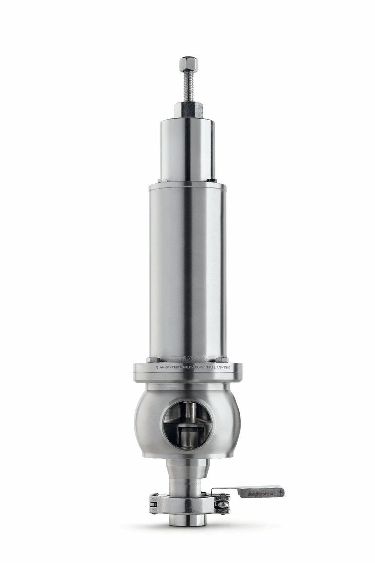
... stainless steel full-lift clean service safety valve designed to AD Merkblatt A2 and TRD 421 standards and suitable for pure steam, vapour and inert gases.
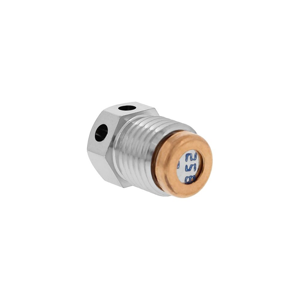
Insert style flow control valves are comprised of a precision orifice in parallel with a check valve, combined into a single component. Each is designed for easy installation into metal housings using ...
Press-in style flow control valves are comprised of a precision flow orifice in parallel with a check valve, combined into a single component. Each part is designed for easy installation into plastic ...
If you have been searching for a safety release valve that you can use to reduce short-term pressure surges successfully and diminish the effects of gas leaks, this is the product for you. With a pe of ...
... have been type tested as well. These pressure regulators have safety valves which will slam shut in the event of emergencies, such as the gas reaching too high a pressure level. The valve ...
This product has hydraulically actuated class A gas safety valves to EN 161 used for automatic shut-off. It shuts off when unstimulated for gas and air, or even biologically produced methane. It has AISi ...
The S 104 Safety Shut Off valve is mainly used to avoid any damage to components as well as to avoid too high or too low pressure in the gas train. This could cause high financial losses and/or injured ...
The S50 Safety Shut Off valve is mainly used to avoid any damage to components as well as to avoid too high or too low pressure in the gas train. This could cause high financial losses and/or injured ...
The S100 Safety Shut Off valve is mainly used to avoid any damage to components as well as to avoid too high or too low pressure in the gas train. This could cause high financial losses and/or injured ...
... Pressure Safety Valve + Rupture Disk is protected and may be utilized autonomously as essential security gadgets or in conjunction. There are 3 possible combinations. The first combinations ...
Excavator pipe-rupture valves prevent uncontrolled cylinder movement in the event that a pipe or hose bursts. The ESV valve fulfills all of the requirements of the ISO 8643 and EN 474-5 standards for ...
Material: Body- CF8M; Valve Seat- CF8M Métal Seat, PTFE Soft Seat available Orifice Size: fc"(15mm), 3/4M(20mm), l"(25mm), l1/4,’(32mm)I ltë”(40mm), ...
The Safety valves from ATOS are designed to guarantee protection for application on various devices, especially those that monitor spool position. They are also recommended for hydraulic ...
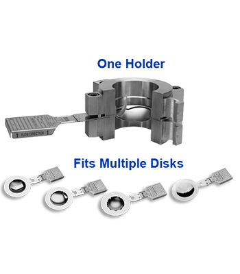
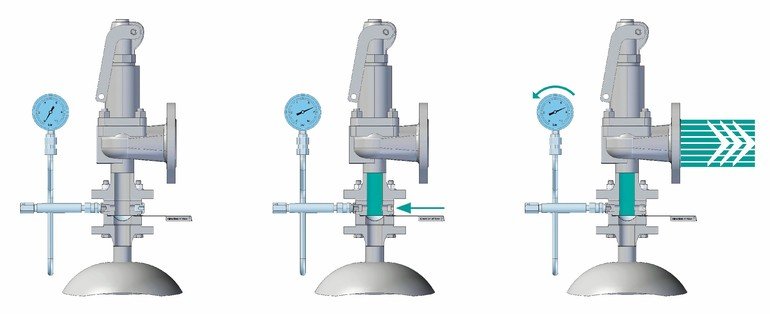
Normally, safety valves have to be removed in order to test whether they are functioning correctly. This is time-consuming and expensive. However, in combination with REMBE® rupture discs, you can test your safety valves without moving them anywhere. To do this, the space between the rupture disc and the valve stroke is pressurised.
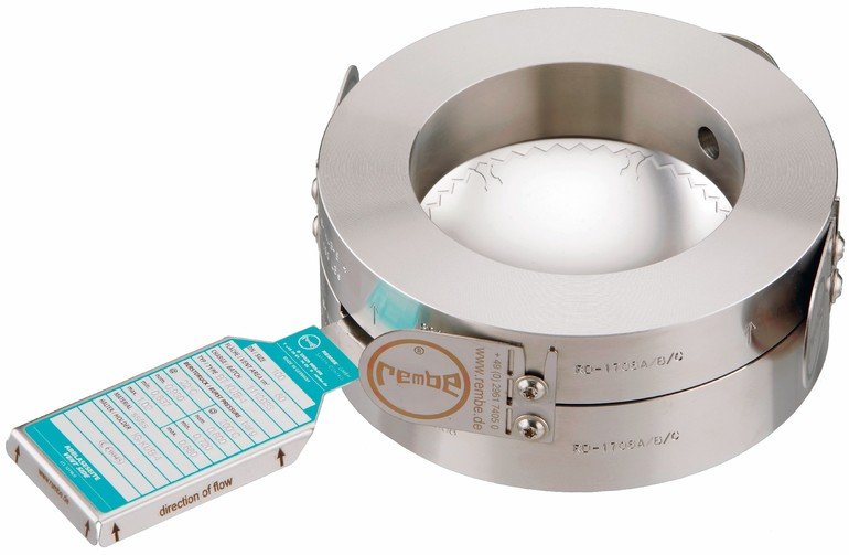
As KUB® has a back pressure resistance of 135 %, the rupture disc remains undamaged while the safety valve is being inspected. If in-house regulations nonetheless require the safety valve to be removed for inspection, the rupture disc can be left in position in a separate flange connection in order to close the opening while this work is being performed.
In-situ test: The space between the rupture disc and the safety valve is pressurised in order to test whether the safety valve is functioning correctly.
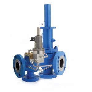
SEMCOR is proud to offer an extensive selection of rupture pin valves from Rupture Pin Technology. What separates Rupture Pin valves from competing products is the uniquely designed and carefully crafted rupture pin that ensures consistent, accurate valve performance within extremely tight tolerances. The patented pin technology also ensures maximum safety during even your most hazardous applications. We also work closely with the staff at Rupture Pin Technology to provide superior customer support for our customers.
Please take a closer look at our complete selection of reliable, high-performing pressure relief valves from Rupture Pin Technology. Feel free to contact us for additional information or to request product literature. Our staff can also help you select the best pressure relief valves for your applications.
The Rupture Pin valve relieves pressure at a specific set point with predetermined accuracy and dependability. This system consists of a piston and seat, restrained from movement by a slender round pin, known as the buckling pin. The piston and seat exhibit a bubble-tight seal while under pressure. The pin will buckle at the predetermined set point from an axial force applied by the system pressure acting on the piston. Each valve is self-contained and self-actuating. Upon buckling of the pin, the valve is left fully open in a matter of milliseconds. The pin is external to the protected system and is tightly held in place at both ends.
Rupture Pin and Buckling Pin valves can be designed to sense system pressure or differential pressure, unlike rupture discs, which can only sense differential pressure.
These systems can also be designed to handle corrosive and dangerous fluids and gases with minimal operating expense and no environmental concerns. This is possible because the systems’ integrity is not compromised during the reset of a Rupture Pin or Buckling Pin Valve.
The exterior of a Rupture Pin relief valve can also be a quarter-turn ball or butterfly valve. Regardless of casing style, all varieties of Rupture Pin valves will adjust to a full open position in only milliseconds.
Certification tests are completed on all valves prior to exiting our facility. ASME standard calls for set point variation of +5%, but rarely deviates over +3% from set point, +1% is common. After successful valve testing, three pins are tested on the Tinius Olsen machine to determine a load vs time curve for the archives. This ensures consistency between pin material lots.
Special machines are used to cut the pins to length perpendicular to the pin axis and polish the cut ends. Every pin is tagged with all pertinent information required to match each pin to its corresponding valve. All valves are stamped with a serial on the bonnet and valve label. New pins may be ordered using only the valve serial number.
Rupture Pin valves have many uses where a non-resetting pressure relief valve is desired and this technology easily replaces existing rupture disc valves. The Rupture Pin relief valve will save on time, operational expenses, and eliminate environmental concerns.
The Rupture Pin valve offers an immediate visual indication that a relief action has occurred, eliminating the need to disassemble your system – as is necessary with disc valve technology. Unlike Rupture Pin Technology, broken disc indicators are unreliable.
This type of valve is easily reset, returning systems to operational in a matter of minutes while eliminating losses due to down-time and added manpower as would occur with rupture disc technology. Rupture Pin technology also allows systems to operate closer to maximum pressures alleviating the fear of premature failure associated with rupture discs.
Many relief valves have been replaced in various system applications with Rupture Pin technology in order to minimize problems associated with mandatory yearly valve testing requirements. For example, spring loaded relief valves are known to leak near set pressure point and pilot operated relief valves tend to get clogged, resulting in a false sense of security. Comparatively, Rupture Pin valves provide a bubble-tight seal until the pin buckles. Unlike spring loaded relief valves, Rupture Pin relief valves offer full opening port at set point.
The Rupture Pin valve offers substantial savings in operating and maintenance costs by eliminating premature failures, preventing the need to break the integrity of the system to institute a reset, avoiding exposure to environmental concerns, and enabling a quick and easy reset when the pin does require changing.Upon conducting a comparison between Rupture Pin, Rupture Disc, and conventional technology for overall return on investment, Rupture Pin wins on every metric (even with a slightly higher initial cost). In terms of ease of use and cleanliness, long-term performance, reliability, problem resolution, and cost savings, Rupture Pin valves have proven to provide greater value than any other technology on the market.
Taylor Valve Technology® is a manufacturer leader in high-quality industrial valves. We deliver safety relief, high-pressure relief, and back pressure relief valves. Our wide array of choke and control valves and pilot-operated valve products are second to none. Products are designed for demanding industrial needs, meeting quality API and ASME Code requirements. High-demand oil & gas industry, chemical plants, power generators, and the processing industry depend on our valves for consistency and durability. Get effective flow control of liquid, steam, and gas. Valves ship from the Taylor Valve Technology, Inc. United States facility. Delivering worldwide, you can depend on quick turnaround times.
Allied Valve is the industry leader in valve sales, service, and distribution. Driven by three key principles – safety, reliability, and quality – Allied Valve is a leading supplier of pressure relief valves, control valves, rupture discs, conservation vents, flame arresters, blanket gas regulators, back pressure valves, actuation, and valve services in the upper Midwest. Helping your business meet tight production schedules and reduce downtime with 24/7/365 services delivered on-time, on-site, and in-person, Allied Valve is your trusted partner to keep your business running seamlessly.
Our factory-trained, OEM-certified technicians deliver time-tested solutions that reduce downtime and costs while maintaining the integrity of your safety program. With locations in IA, IL, IN, MN, ND, OH, and WI, our 100+ certified service technicians are at your service. We operate five Consolidated Green Tag Centers, two authorized Kunkle Assemblers plants, and five Masoneilan™ Authorized Repair Center (MARC™), dedicated to providing quality products.

As with the single safety relief valve installations employing a rupture bursting disc, the double safety valve combinations may also be protected by installing this useful device directly before the inlet connection of the pressure relief valves. The bursting disc prevents the operating medium from having contact with the PRV’s inlet and so avoids contamination or corrosion of the safety valves.
The inlet and outlet diameters for the pressure relief valves are from DN 10 (3/8’’inch) to DN100 (4’’ inch). The performance ratings for flow – pressure drop – and many more information you will find by using our selection software ValveCalc and our operation instructions.
The set pressure ranges for the safety relief valves begin at 4 bar and have a maximum level at 63 bar. The lowest working temperature is at -60 C° (- 76 F°) and the highest operating temperature is 180 C° (356 F°).
For the manufacture of safety relief valves and for the pressure relief valve combinations we offer housing bodies from a range of various materials. These include carbon steel (CS), stainless steel (SS), low temperature steel (LTCS). The choice of valve bodies offered may be of a welded tube fabrication type, a casting or a forging.
The connections include all flange types, welded joints and threaded connections. The pressure relief valve stem sealing system employs neoprene or PTFE seals.
Safety valve model ZV is a high lift safety valve with stainless steel seat, valve body and internals suitable for use on steam, air and water. ZV is a pressure relief valve actuated by rapid opening or pop-action.
The safety valve is normally set at a pressure which is 10% above the working pressure of the system. This is referred to as the set pressure, at which the oozing of the steam starts.When the system pressure reaches blow off pressure the safety valve opens to its full lift to discharge full capacity. The valve closes at reset pressure.
Project: Gas mixing panel Gas: Oxygen Pressure Safety Valve Size: G3/8” or ½” + Material: Brass or Equivalent suitable oxygen service + Set pressure: 170 bar + Working pressure: 150 bar + Q’ty: 1 Pc - Document request: + Detail drawing with a material component + Certification oxygen cleaned + Certificate type approval for Oxygen
Because a safety valve is often the last device to prevent catastrophic failure under pressure conditions, it is important that the valve works at all times i.e. it must be 100% reliable.
Safety valves should be installed wherever the maximum allowable working pressure of a system or pressure containing vessel is likely to be exceeded, in particular under fault conditions due to the failure of another piece of equipment in the system.
The term “Safety Valve” and “Relief Valve” are generic terms to describe a variety of pressure relief devices. A wide range is available based on the application and required performance criteria. The different designs are required to meet numerous national standards.
The images below show the devastating results of a failed Safety valve (due to poor maintenace) or ones which have been incorrectly sized, installed or maintained.
A spring-loaded pressure relief valve which is designed to open to relieve excess pressure and to reclose and prevent the further flow of fluid after normal conditions have been restored. It is characterised by a rapid-opening "pop" action or by opening in a manner generally proportional to the increase in pressure over the opening pressure. It may be used for either compressible or incompressible fluids, depending on design, adjustment, or application.
Relief valve - A pressure relief device actuated by inlet static pressure having a gradual lift generally proportional to the increase in pressure over opening pressure.
Safety relief valve - A pressure relief valve characterised by rapid opening or pop action, or by opening in proportion to the increase in pressure over the opening pressure, depending on the application, and which may be used either for liquid or compressible fluid.
Safety valve - A valve which automatically, without the assistance of any energy other than that of the fluid concerned, discharges a quantity of the fluid so as to prevent a predetermined safe pressure being exceeded, and which is designed to re-close and prevent further flow of fluid after normal pressure conditions of service have been restored.
The images below show a standard Relief valve and a standard Safety valve from a well-known UK manufacturer. Each manufacturer does things slightly differently however all of the basic components and principles of operation are the same. As described previously, a safety valve differs from a relief valve in that it opens rapidly once the set pressure has been reached. For the same inlet size and with the valve in the closed position, the surface area that the pressure on the inlet side will see is the same. When the set pressure is reached and the valve starts to open, the disk on a Safety valve is larger (see the diagrams below) and hence the same pressure then sees a much larger surface area and consequently the force increases greatly causing the valve to open quickly and hence the characteristic pop action.
The image below shows the above Safety valves and Relief valves dismantled. The disk diameter on the 1" (DN25) Safety valve is only 7mm larger than on the Relief valve which doesnt sound like much, but when you calculate the areas it is an increase of 36%.
This diagram represents a Safety valve in its very simplest form. The force acting on the inlet side of the disk is acting against the force applied by the spring plus the force applied by the back pressure on the top of the disk.
The valve remains closed when(PI x Ab) < Fs + (PB x At), is in equilibrium when(PI x Ab) = Fs + (PB x At) and opens when(PI x Ab) > Fs + (PB x At) were PI = Inlet pressure, PB = Back pressure, At = Top of disk area, Ab = Bottom of disk area. Things to notice from this design are that if PB is variable and quite large relative to PI, then this will cause the pressure at which the valve opens to vary which is undesirable. The following two designs (Fig 3 & Fig 4) are available that eliminate the effect of back pressure on the set pressure.
The bellows prevents backpressure acting on the top side of the disk. In relation to the piston there is no top side within the main body of the valve hence again the back pressure cannot affect the set pressure. Bellows failure is an important concern in critical applications where a very precise set pressure is required. In these cases some mechanism to detect a leak of process medium out of the top vent would be implemented. Piston designs are not usually found in conventional Safety valves but are more common in Pilot Operated Safety valves.
API 520 Practice Guidelines: a conventional design should not typically be used when the built-up backpressure is greater than 10% of the set pressure at 10% over pressure. European standard EN ISO 4126: the built-up backpressure should be limited to 10% of the set pressure when the valve is discharging at the certified capacity.
Overpressure is the percentage over the set pressure by which the valve is fully open. The blowdown is the percentage below the set pressure by which the valve is fully closed.
The basic elements of the design are right angle pattern valve body, inlet can be either a full nozzle or a semi-nozzle type. With a full nozzle design has the “wetted” inlet tract formed from one piece (as per figure 6) with the seat integrated into the top of the nozzle. The internal bore of the nozzle and the disc is the only part of the valve that is exposed to the process fluid with the valve in the closed position. A semi-nozzle design consists of a seating ring fitted into the body.The disc is held onto the seat by the stem, with the downward force coming from the compression on the spring mounted in the bonnet. The amount of compression on the spring is adjusted by the spring adjuster under the cap.
Unless bellows or diaphragm sealing is used, process fluid will enter the spring housing (or bonnet). The amount of fluid depends on the particular design of safety valve. If emission of this fluid into the atmosphere is acceptable, the spring housing may be vented to the atmosphere - an open bonnet. This is usually advantageous when the safety valve is used on high temperature fluids or for boiler applications as, otherwise, high temperatures can relax the spring, altering the set pressure of the valve. However, using an open bonnet exposes the valve spring and internals to environmental conditions, which can lead to damage and corrosion of the spring.
When the fluid must be completely contained by the safety valve (and the discharge system), it is necessary to use a closed bonnet, which is not vented to the atmosphere. This type of spring enclosure is almost universally used for small screwed valves and, it is becoming increasingly common on many valve ranges since, particularly on steam, discharge of the fluid could be hazardous to personnel.
A lifting mechanism is recommended to test for correct valve operation at all times where corrosion, caking, or any deposit could prevent the opening operation.
Foreign particles can lodge under the seat of the valve when it discharges. The lifting lever allows you to lift the valve and flush the obstruction. Pressure relief valves for Section VIII require a lift lever on all air, steam, and hot water valves used at temperatures over 60 degC. Typically used where periodic testing of the valve in location is desired to assure its operation. With an Open lifting lever design, when the valve discharges, fluid media will escape into the atmosphere around the open lifting lever assembly. If this is not desirable or when back pressure is present you would select a Packed Lifting Lever design.
As described above, this type is selected where leakage of the media to the atmosphere during valve discharge or during back pressure would be un-desirable. A packed lever design is a completely sealed assembly.
Under certain circumstances i.e. under the start-up conditions of a plant or to pressure test the system in a controlled environment, it may be required that the valve is prevented from opening.This is achieved by screwing the bolt (shown on the wire) into the cap which screws down onto the stem and prevents it lifting. Obviously it is important that test gags are removed prior to placing the valve into service.
The bellows is designed to cover the same area on the back of the disc equal to the seat area hence the back pressure will have no effect on the set pressure. See the previous section “Basic Safety Valve Principles”. Bellows also protects the spindle, spindle guide and spring from the process medium.
A disc is held against the nozzle by a spring, which is contained in a cast bonnet. The spring is adjusted by a compression screw to permit the calibration of opening or set pressure. An adjustable nozzle ring, threaded onto the nozzle, controls the geometry of the fluid exit control chamber (also known as a huddling chamber). The control chamber (huddling chamber) geometry is very important in controlling valve opening and closing pressures and stability of operation. The nozzle ring is locked into position by a ring pin assembly as shown in Figure 15 below.
Under normal system operation the valve remains in the closed position because the spring force (Fs) is greater than the system pressure acting on the internal nozzle seating area (PA). If system pressure increases to a point when these forces are equal, then the set pressure is reached. The disc lifts and fluid flows through the valve. When pressure in the system returns to a safe level, the valve closes.
Just prior to reaching set point, the pressure relief valve leaks system fluid into the huddling chamber. The fluid now acts on a larger area of the disc inside the huddling chamber (PAh), causing the valve to experience an instantaneous increase in the opening force. Refer to the figure 16 above to see relationship between Nozzle Area (A) and the Huddling Chamber Area (Ah). System pressure acting on the larger area will suddenly open the safety relief valve at a rapid rate.
Although the opening is rapid and dramatic, the valve does not open fully at set point. The system pressure must increase above set point to open the valve to its full lift and capacity position. Maximum lift and certified flow rates will be achieved within the allowable limits (overpressure) established by various codes and standards. All pressure relief ales are allowed an overpressure allowance to reach full rated flow. The allowable over pressure can vary from 10% to 21% on unfired vessels and systems, depending on the sizing basis, number of valves, and whether a fire condition is encountered.
Once the valve has controlled the pressure excursion, system pressure will start to reduce. Since the huddling chamber area is now controlling the exit fluid flow, system pressure must reduce below the set point before the spring force is able to close the valve. The difference between the set pressure and the closing pressure is called blowdown, and is usually expressed as a percentage of set pressure. The typical blowdown can vary from 7% to 10%, the industry standard.
The nozzle ring adjustment changes the shape and volume of the huddling chamber, and its position will affect both the opening and the closing characteristics of the valve. When the nozzle ring is adjusted to its top position, the huddling chamber is restricted to its maximum. The valve will usually pop very distinctly with a minimum simmer (leakage before opening), but the blowdown will increase. When the nozzle ring is lowered to its lowest position, minimal restriction to the huddling chamber occurs. At this position, simmer increases and the blowdown decreases. The final ring position is somewhere between these two extremes to provide optimal performance.
On liquid service, a different dynamic situation exists. Liquids do not expand when flowing across orifices, and a small amount of fluid flow across the nozzle will produces a large local pressure drop at the nozzle orifice. This local pressure drop causes the spring to reclose the valve if the fluid flow is minimal. Liquids leaking into the huddling chamber can quickly drain out by gravity and prevent fluid pressure from building up in the secondary area of the huddling chamber. Liquid relief valves are thus susceptible to a phenomenon called chatter, especially at low fluid flow rates. Chatter is the rapid opening and closing of the pressure relief valve and is always destructive.
Because of the difference in the characteristics of gases and liquids, some valve designs require a special liquid trim in order to meet ASME Code Section VIII performance criteria of full rated liquid flow at 10% overpressure. With liquids since no visible or audible pop is heard at set point, the set pressure is defined as the pressure when the first heavy flow occurs (a pencil sized steady stream of water that remains unbroken for approximately one inch).
If you have a system that is shut down for annual maintenance then this is an ideal time to remove your Safety valves and have them inspected and recertified.
For systems that can only be off for short periods of time, it is sensible to keep a spare valve to swap over and then the removed valve can be inspected and recertified.
For systems that cannot be shut down, you will need to use a changeover valve which allows you to swap between Safety valves allowing one to be removed for inspection and testing.
For larger Safety valves on systems that run continuously, you may consider using in-situ testing. This method does have some limitations however since you cannot visually inspect the inside of the valve, but it will tell you if the valve is opening at the correct set pressure.
(a) A valve passing (leaking) on the outlet side when the valve is supposed to be closed. This can happen to valves of any age (new or old) and occurs if debris contained in the medium passes through the valve at a point when the valve lifts, and the debris either traps or damages the internals of the valve. On soft seated valves, hard particles may embed themselves in the soft material causing re-sealing issues. If your valve has a lifting lever and it is safe to do so, then it is worth lifting the handle for a few seconds which will hopefully clear any debris allowing the valve to reseal correctly. If this isn’t an option or it doesn’t cure the problem, then the valve will need to be removed and returned for maintenance and recertification. The time we often see this the most is during the startup of a system and there is a pressure spike, hence this is why it is extremely important that a system is flushed out well before hand.
Of all the challenges you face keeping your customers’ plants operating at full capacity, safety and relief valves shouldn’t be one of them. NASVI’s job is to give you the confidence that your valve supply chain is rock solid regardless the pressure it’s under.

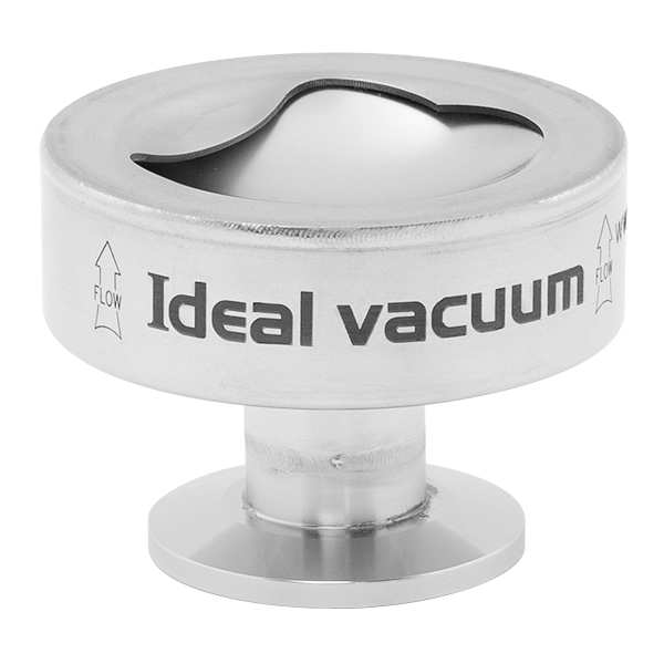
Stainless Steel Safety Relief Valve is a safety mechanism deployed in applications to prevent them from bursting under pressure. Suraj Metal Corporationis a leading manufacturer and supplier of the different types such as the Brass Safety Valveand others in various sizes and dimensions. The valves are fitted with the pipelines in a way that when the pressure goes above the threshold level, the Stainless Steel Air Safety Valveopens up and relieves the system of pressure.
This is important to prevent the pipes from being damaged or bursting under high pressure. The Stainless Steel Safety Exhaust Ball Valveis used in the exhaust systems where the temperature plays major role. When the temperature exceeds certain point, it increases pressure and the safety valve opens and balances the pressure in the system. The spring loaded boiler safety valveis used in boilers and heat exchanger systems where steam and hot water are circulated through pipes. There are different gas safety valvetypes and each of these differ in their purpose and functions. Please feel free to contact us for more information on the different types of air compressor pressure relief valveand others with pricing.
We Keep Bulk Stock of CF8 stainless steel Pressure Safety Valve at our stockyard, contact us for Free Sample & stock list, View Brass Safety Valve Dimension chart
find Stainless Steel Safety Exhaust Ball Valve Dimensions, price list, size chart here, Buy ASTM A351 CF8M 316 temperature safety valve at best price in India
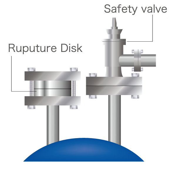
Changes in the law and ever stricter environmental regulations are forcing plant owners to reduce their emission levels. This also applies to pressure relief devices such as safety valves. To avoid having to use far more expensive valves – which are often difficult to retrofit – it is a good idea to install a rupture disc upstream of the safety valve.
The first step towards fulfilling the regulations was to try and find better safety valves, which were simple to build into the design of new valves. However, substantial investments were necessary to upgrade the older designs of existing plants with newer ones – not an economical choice in the majority of cases. Even with new plants, there was a significant increase in safety valve costs in the endeavour to meet the lower emission levels required for certification and permits, to be allowed to start up a plant or continue operating it.
Although the capabilities of safety valves were expanded considerably, they were still not able to comply with the requirements envisaged for future zero targets. In fact, it was believed that they never would do and so an alternative solution was needed.
Rupture discs have been around for decades but have always been seen as a second-choice alternative for overpressure compared to safety valves – the poor relation of the safety valve industry, as it were, a title they do not deserve. This lack of understanding of rupture discs continues to this day. Discs are a “problem”: they open and let the pressure out, when in fact that is exactly what they are designed to do. Many operators remain blissfully unaware that when the disc performs correctly, this is not the problem but the solution.
So how do rupture discs help safety valves perform better in use? Well, when it comes to isolation, they partner safety valves and deliver the superior performance needed to realise zero emissions which a stand-alone safety valve cannot provide. Although safety valves can achieve good performance levels on their own, one hundred percent isolation and better operational stability require the use of rupture discs. For several years now, rupture discs have been regularly installed upstream of safety valves. Operators are starting to appreciate that a properly engineered rupture disc will help lower their operating costs and increase plant uptime. The belief that this arrangement adds more cost to a project has been proven to be false; in fact, the opposite is true and the costs actually come down.
Let us take a typical installation where the safety valve faces a process condition with a high concentration of corrosive materials, elevated temperatures and an operating pressure close to the valve’s set pressure. The safety valve’s limits are put to the test, leading to poor performance below the expected levels for operational stability and leakproofness. High maintenance costs are incurred to keep the valve as close as possible to the original specs, along with increased downtime for routine valve servicing and/or repairs and higher manpower costs to handle the work.
The solution suggested by safety valve manufacturers is a valve with a higher specification, more exotic materials with higher capex costs and more expensive spares for maintaining the valves. In an average petrochemical plant with several hundred safety valves, this capex translates into a dramatic increase in valve inventory costs.
Rupture discs fitted upstream of the safety valve, in a material that will isolate and withstand the process conditions, let the plant owner install lower grade materials in the valve while still meeting all the design requirements, though with a significant reduction in the safety valve capex.
The costs for the rupture disc and holder are negligible compared to the capex for an exotic or higher-specification safety valve. If account is also taken of the lower expenditure on maintenance, the disc and holder are free of charge. In fact, this is a win-win path with more production uptime, less emissions, greater safety, lower overall maintenance costs and reduced inventory.
Yet, we still see safety valves with an upstream rupture disc failing, needing maintenance and stopping production or causing safety issues. So what went wrong? Remember that a safety valve also has an outlet. In many cases, this outlet is not a separate line to discharge but is manifolded together with other parts of the plant, allowing process gases or vapour to enter it and provoke safety valve failures. This is something easily eliminated by a downstream rupture disc, which prevents any process gases from entering the safety valve on the outlet side. The rupture disc will also block any back pressure attempting to enter the safety valve and eliminate such concerns during valve selection.
With burst sensors installed both upstream and downstream, rupture discs can be monitored and connected back to the control room for system reporting across the plant, so that operators know instantly which valves and discs are in a green or red state.
The rupture disc manufacturer can collaborate with design and process engineers to select the discs giving the best possible safety and isolation performance. Unfortunately, this is still a rarity and is a factor in the rupture disc being blamed for poor performance when all it is actually doing is what it was designed to do, namely be the most important safety device in the plant – the only fail-safe device that always opens when faced with an overpressure situation.
Rembe was approached by a refinery to help overcome serious issues with its safety valves due to process conditions attacking the metal structure. The requirement was to enable the plant to be operated for three years without having to remove the safety valves for servicing and recertification except in an emergency. When the safety valves were removed during a scheduled shutdown, several of them were found to have broken or cracked springs while others were corroded to failure point. Bellows were corroded and broken. Several safety valves were so badly affected that the disc and nozzle were corroded solidly together and the valve was unable to open. This raised major safety concerns that the plant could no longer meet its three-year maintenance-free plan and it was decided to return to the old test method of regular safety valve removal and replacement.
An analysis carried out in conjunction with Rembe showed that aggressive process gases were present both upstream and downstream of the valves, and that isolation with rupture discs in a suitable material would offer the best protection. What’s more, the user would stand a more realistic chance of meeting the three-year target, with the ultimate goal of extending this to five years.
In addition, the use of KUB V rupture discs allows for in-situ lift testing of the safety valves on site during the three-year period, to ensure that they are still operational. As a further benefit, the costs are lower because the Rembe rupture discs can be removed, inspected and reused, and are still in serviceable condition.
Emerson Crosby brand has maintained its leadership in overpressure protection. The direct spring-operated safety and pressure-relief valves PRV are among the world’s most widely used for oil and gas production and refining, petrochemical and chemical processing, and conventional and nuclear power. With the Crosby brand, Emerson maintains the industry’s most extensive high-flow facilities for valve testing in air, steam, and water.
In recent years several industries have recognised the need to isolate or protect the inlet of safety valves with rupture discs, but many have missed the opportunity to fully protect the safety valve from the effect of process conditions entering the outlet side of the valve.
The first step was to try and find better safety valves, which for new plants was simple to build into the design. But existing plants were looking at substantial investments to replace older designs with newer ones, not an economical choice in a large majority of cases. Even for new plants there was a significant increase in safety valve costs to try and meet the lower emission levels required for certification and necessary permits to allow start up and be able to continue to run the plants.
While there were increases in the capabilities of safety valves, it was still not ideal or meeting the requirements visualised for future zero targets. The expectation was that safety valves could not meet the requirements and an alternative solution was needed: enter the rupture disc.
Rupture discs have been around for decades and were always seen as the secondary solution for overpressure after safety valves, the second-class citizen of the safety valve industry, a title they do not deserve! The lack of understanding of the rupture disc continues to this day. It is still a mystery to engineers in the mechanical and process disciplines and to the field operatives that install and maintain them, or in a lot of cases ignore them.
Well in the case of isolation it partners the safety valve and brings the superior performance needed to meet zero emissions more than a stand-alone safety valve provides. Yes the safety valve can have good performance levels on its own, but achieving 100% isolation and providing better operational stability requires the use of rupture discs.
For several years now we have regularly seen rupture discs being installed upstream of a safety valve. Operators are now starting to appreciate that a properly engineered rupture disc will help lower their operating costs and increase the up-time for a plant.
Take a typical installation where the safety valve faces a process condition with high concentration of corrosive materials, increased temperatures and an operating pressure close to the safety valve set pressure. This tests the limits of safety valves and we see poor performance below the expected levels needed for operational stability and no leaks. High maintenance costs are needed to keep the valve as close to original specs as possible, increased downtime to the production for routine valve servicing and/or repairs and higher manpower costs to cover the work scopes.
The solution of the safety valve manufacturers is a higher specification valve, more exotic materials with higher CAPEX costs as well as increased cost of spares to maintain the valves.
The use of a rupture disc in front of the safety valve allows for the use of valves in standard materials, isolated from the process by a ‘more exotic’ rupture disc.


 8613371530291