
floor jack safety valve adjustment price
An overload valve of a floor jack primarily exists so that the jack does not exceed the weight limit of the hydraulic press, which might cause it to break down. Overload valves stop the press from lifting further up if the weight limit is crossed.
The floor jack overload valve adjustment process is very straightforward and only requires you to follow a set of simple steps. However, if you’re trying to adjust the overload valve, chances are that your floor jack is having some trouble holding pressure. In that case, we have some solutions for that as well.
An overload valve is a safety measure to protect the hydraulic press from unwanted damage due to excessive pressure. It works by loosening the connection between the jack handle and the hydraulic press.
When we’re talking about adjusting the overload valve, we’re mainly changing the max weight capacity of the floor jack. To do that, you just need the right screwdriver. It varies from model to model, some use Philips heads while others use binding heads.
Once you’ve got the right screwdriver, find the location of the safety valve. There will be a shield on top of it that you’ll have to remove with the screwdriver. Spot the screws and turn them counterclockwise to release the shield.
After you’ve done that, the valve should be exposed to you. There are mainly two types of valves used on floor jacks. The handle valve and the screw valve. Handle valves have a handle, while screw valves have a hole for the screw to go through.
For a handle valve, you just have to hold on to the handle and rotate it to adjust the weight overload on the floor jack. Rotate it clockwise to increase the maximum weight capacity and counterclockwise to decrease it.
These valves are typically very sensitive so a small turn could drastically change the output. So, try it in small amounts and figure out the correct amount for you.
For a screw valve, you will need a corresponding screwdriver. Typically it is the same as the shield’s screws, but according to your model, it could be different.
Safety Note: Before attempting to put pressure after adjustments, check the instruction manual of the floor jack for the maximum supported weight capacity. Normally, the valve will be set to 90% of that max capacity. So, you can at best increase it to 100%. Going beyond that will be very risky as it can damage both the floor jack and your vehicle.
This is a very common issue for which people consider adjusting the overload valve. A loose valve can indeed cause your floor jack to suffer such problems. However, that’s not the only cause.
The hydraulic press will fail to operate if the oil levels are above or below the given margins. Also, if the oil is of low quality, it might cause friction which can also prevent it from working properly. To maintain the proper hydraulic level, you should fill your jack with oil correctly and safely.
To know exactly what types of fluid are used in a floor jack, check out this article where we have explained and recommended the hydraulic fluid to use in your jack.
Hydraulics work by using highly pressurized compressed air. After long-term use, some of that air can leak into other parts of the machine causing havoc. The air mostly gets trapped in the oil chamber. To remove air from the floor jack, you just need to bleed it.
The final most obvious consideration would be that the floor jack is damaged. In most cases, it’s the hydraulic press. Repairing a broken floor jack is not worth the effort and the money. You’re better off getting a new floor jack.
Keep in mind that the overload valve is a safety measurement. So, a floor jack overload valve adjustment should only be done under your own circumstances. To be on the safe side, never exceed the given weight limit of your floor jack.
When was the last time that you had your vehicle"s valves adjusted? Known as a valve adjustment or valve clearance adjustment, it"s a routine form of maintenance recommended for most vehicles with a combustion engine. Unfortunately, it"s also something that many motorists overlook. It"s not until they experience problems with their vehicle that they realize the need for a valve adjustment. To learn more about valve adjustments and how they work, keep reading.
So, what is a valve adjustment exactly? To better understand this maintenance procedure, you must first look at the valve system of a typical combustion engine. The valve system consists of pushrods, lifters and rocker arms. Supported by lifters and rocker arms, the pushrods move up and down to open the intake valve. Over time, however, it"s not uncommon for the clearance between these components to increase (or decrease in some cases). A valve adjustment, however, is designed to move the valves into the appropriate position, thereby eliminating problems associated with excessive clearance.
If your vehicle"s engine needs a valve adjustment, you may hear a loud clanging or clinking sound originating in the engine bay. This occurs because of the valves large clearance space. Since the pushrods aren"t secure in place, they don"t glide smoothly up and down.
Another common sign your vehicle"s engine needs a valve adjustment is rough idling. If the valves don"t open the intake and exhaust at the right time, it will restrict airflow into the engine, which may manifest as rough idling.
Incorrect valve clearance can also lead to oil consumption. If you notice the level on your vehicle"s dipstick gradually lowering, you should consider taking your vehicle to the shop for a valve inspection, and if necessary, a valve adjustment as well.
You should refer to your owner"s manual to find out when, exactly, your vehicle"s valves should be inspected by a mechanic. Some automakers recommend a valve inspection every 60,000 miles, whereas others recommend a valve inspection every 100,000 miles. During an inspection, a professional mechanic will determine whether your vehicle"s engine needs a valve adjustment.
The cost of a valve adjustment varies depending on several factors, including the make and model of your vehicle, the mechanic from whom you purchase the service, your geographic location and more. With that said, the average cost of a valve adjustment is about $150 to $300, assuming no other work or parts are required.

The present invention relates to an improved safety valve structure for a hydraulic jack, particularly to an improved structure of the safety valve inside a pump base of the jack so that high pressure hydraulic fluid can smoothly and accurately flow through the valve and return to a reservoir.
A one-way valve is usually provided between the reservoir and the pump base of a hydraulic jack. The one-way valve is used to control hydraulic fluid flowing from the reservoir into a pump. The valve also cooperates with the up-and-down movement of a lever on the jack so that the hydraulic fluid can be forced into a pressure tank for pushing a piston upward. When the jack is overloaded and the hydraulic pressure inside the jack has reached a predetermined limit, a safety device is needed to discharge the hydraulic fluid back into the reservoir. A conventional safety device uses a steel ball and a safety spring secured by an adjustment screw. The adjustment screw is used to adjust the pressure of the safety spring which presses against the steel ball. When the pressure inside the pressure tank is higher than the pressure of the safety spring set by the adjustment screw, the steel ball will automatically be pushed rearwardly against the force of the safety spring so that the safety spring is compressed, thus enabling the steel ball to disengage from a valve seat. Thus, the path previously closed by the steel ball is opened and the hydraulic fluid can return to the reservoir, thereby lowering the pressure within the pressure tank and preventing the pressure tank from cracking or exploding. However, the operation of the above arrangement is not reliable, since it is easy for the steel ball to deviate from an opening path of movement. Therefore, discharge of the hydraulic fluid is unstable and results in rough operation.
The main object according to the present invention is to provide an improved safety valve structure for hydraulic jacks. The structure is provided with a push pin, a safety spring and an adjustment screw. The end of the push pin is placed inside the axial hole of the adjustment screw. The adjustment screw is used to adjust the compression of the safety spring so as to control the pushing force of the push pin. By such configuration, the push pin can be used to seal the opening as well as to guide the hydraulic flow when the push pin is retracted. Thus, it provides for smooth operation when the hydraulic oil is discharging.
As shown in FIGS. 2 and 3, a safety valve according to the present invention is provided inside a valve body of a one-way valve 1 of a hydraulic jack. The one-way valve 1 is provided inside a pump base 6 of the hydraulic jack and a pump 7 is provided on the pump base 6. The one-way valve 1 includes a cylindrical valve body. The cylindrical valve body has an annular recess or slot 11 formed in an exterior wall thereof.
An L-shaped oil inlet channel 12 defines an oil inlet port 121 at slot 11 and a port opening at the top surface of the one-way valve 1. A filtering screen is provided in the inlet channel 12 at oil inlet port 121. The L-shaped oil inlet channel 12 is a two-step channel having a larger diameter portion at the top and a smaller diameter portion at the bottom. A steel ball 123 and a compressed spring 124 are provided in the larger portion of the channel. The compressed spring 124 engages a projection defining the upper opening so as to be secured without disengaging. Also, the steel ball 123 seals the upper neck opening of the smaller diameter portion of the channel. In addition, the top surface of the one-way valve 1 is provided with an oil discharge port or hole 13, which is a two-step passage or hole having a larger diameter bottom portion and a smaller diameter top portion. The larger diameter portion of the channel is provided with a steel ball 131 and a compressed spring 132. The compressed spring 132 is secured in place by engaging an inwardly extending projection defining a bottom opening. Also, steel ball 131 seals the bottom opening of the smaller diameter portion. In addition, the wall of the annular slot 11 of the one-way valve 1 is provided with a safety oil discharge port or hole 14, which communicates with the smaller channel portion of the oil discharge port or hole 13.
As shown in FIGS. 2 and 3, the safety oil discharge hole 14 is a two-step passage or hole having a smaller diameter portion 141 which communicates with the smaller portion of the oil discharge hole 13. A rearward section of a larger diameter portion 142 is provided with inner screw threads. A push pin 2, as well as a safety spring 3, are placed in the larger portion 142 and an adjustment screw 4 is used to secure the pin 2 and spring 3 in place. A forward portion of push pin 2 is a cone-shaped body 21 and a rearward portion is a two-step rod or post 22, in which a large-diameter portion is inserted into the safety spring 3 in the axial direction, the small-diameter portion is inserted into an axial hole 41 of the adjustment screw 4. In this configuration, the resilient force of the safety spring 3 is applied so that the cone-shaped body 21 of the push pin 2 seals an end of the smaller portion 141 of the safety oil discharge passage 14. An end of safety spring 3 is engaged by adjustment screw 4, which is screwed and secured inside the larger portion 142 of the safety oil discharge hole 14. Also, the force of the safety spring 3 and thus the sealing force of push pin 2, can be adjusted by adjusting the adjustment screw 4 in the larger portion 142 of the safety oil discharge hole 14. In addition, the axial hole 41, provided on top of the adjustment screw 4, is used for discharge of the hydraulic fluid.
By use of the push pin 2, provided in the safety oil discharge hole 14 to cooperate with the safety spring 3 and the adjustment screw 4, the pump 7 can be removed and the one-way valve 1 can be taken out. By turning the adjustment screw 4, the compression ratio of the safety spring 3 can be set and the force of the push pin 2 acting against the smaller portion 141 of the safety oil discharge hole 14 can also be adjusted. Thus, the force from the safety spring 3 pushing against the push pin 2 can be set as the critical value of the hydraulic safety load coefficient. In other words, safety spring 3 and push pin 2 limit the pressure of the hydraulic jack. During operation, when the safety load value of the hydraulic fluid within the jack reaches the limit (i.e., when the load exceeds the setting of the push pin 2), the push pin 2 inside the safety oil discharge hole 14 is displaced backwardly by the hydraulic pressure and compresses the safety spring 3. At this time, the push pin 2 disengages from the smaller portion 141 of the safety oil discharge hole 14 and therefore, the hydraulic circuit is a closed circuit. This means that the hydraulic oil can circulate through the safety oil discharge hole 14, the axial hole 41 of the adjustment screw 4, the annular slot 11 of one-way valve 1 and return into the oil storage tank, allowing the pressure inside the jack to be depressurized. When the pressure inside the hydraulic jack decreases to within the safety load limit, the force from the safety spring becomes higher than the internal hydraulic pressure of the hydraulic jack, and therefore, the safety spring 3 automatically biases the push pin 2 forward so as to seal off the small portion 141 of the safety oil discharge hole 14. By this setup, the safety of the hydraulic jack can be assured and an explosion can be prevented. In addition, the push pin 2 is a linear fluid guide inside the safety oil discharge hole 14. When the latter is discharging, turbulence is prevented and a smooth operation can be assured. It is indeed a compact, practical and modern design.
By use of the above configuration, the flow of the hydraulic oil is described as follows: when the lever 5 is pulled up, the hydraulic oil inside the reservoir is sucked through an inlet 61 inside of the pump base 6. The oil follows the L-shaped oil inlet channel 12 and flows into pump 7. When lever 5 is pressed downwardly, hydraulic oil inside pump 7 is forced out through oil discharge hole 13 of the one-way valve. The oil follows an outlet path 62 of pump base 6 back into the pressure tank of the hydraulic jack so as to drive a piston up for lifting (now shown in Figure). However, if the lifting load of the jack exceeds the maximum design load and a user continues to operate lever 5 to force hydraulic oil into the pressure tank; the pressure could cause the pressure tank to crack or explode. Therefore, when the hydraulic pressure exceeds the safety limit, the improved safety valve structure, according to the present invention, allows the hydraulic pressure to push the push pin 2 inside the safety oil discharge hole 14 backwardly so that the hydraulic oil can follow the path through the annular slot 11 and through the inlet path 61 of the pump base and then return into the oil reservoir. Thus, the pressure inside the pressure tank can be controlled. In addition, the structure of push pin 2 provides a linear fluid guide so that the oil flow is smooth and accurate.

Hydraulic Jacks need to be bled on occasion, This can be account of a Low Oil situation allowing Air to be ingested, Heavy Movement which can allow the oil to slosh around in the Reservoir or a Weak or Poor Pump seal that will extrude Oil/Air into the system. A General rule of thumb is 1st make sure there is sufficient oil in the Reservoir, then simply put the jack in the Release position and Pump the Handle 6-8 times. What this will do is make the circuit between the Reservoir, Through the Valve system, Through the Release vein and back into the Reservoir all the time purging the lines from any Air.
A general Rule of Thumb is on Floor jacks, The oil should rest aprox 5/16" below the fill hole or rest just above the inner cylinder, when peering thru the hole. On bottle jacks the Fill hole is generally on the Reservoir aprox 3/4 of the way up, It should be filled till oil starts to trickle out of the hole when the jack is in the Upright position. Always Check oil levels with the Jack arm lowered or Bottle jack Ram retracted.
2. Unfortunately the Next step requires you to tear into your jack and Inspect the Individual Seals. There are some Tutorials Available to cover some of the Most Popular Models.
1. Now i cant get the Tank Nut off... Grr... Ok first and Foremost, Make sure it is a Threaded Nut, Some Jacks use a Internal C-clip to get to the Ram. If its Threaded The Thread is always been Standard (Lefty Loosey/Righty Tighty). These Tank nuts are Extremely tight, because alot of them (not All) need this torque to seal the Reservoir at both ends (Metal to Metal). First and Foremost, a Proper sized Tool will play dividends, If you dont have the proper sized socket/Wrench you can use a Pipe Wrench on the "Hex" style nuts. It will leave teeth marks, If this bothers you... Go buy the Correct Socket.
2. Next you will need a Vise or Press capable of Holding the Unit while you attempt to unscrew the Nut, Dont be afraid to add Leverage, I keep a 6ft piece of Square tubing that slips over a Breaker bar. I also manufactured a piece that mounts between the floor and the nose of the Unit to keep things on the level while i levy on that cheater bar.
When you adjust the Plug down it compresses the Spring which in turn adjusts the Seating pressure of the Ball/Cone. All of your seals have a Maximum Operating PSI, When the Overload is properly adjusted it is set to OPEN up when the Cylinder PSI exceeds the Working pressure of the Seal. This Setting will Vary from Jack to Jack, Based off of the Cylinder Bore/Spring Tension etc.. Ive found that over the Years these Heavy springs which are compressed for there entire life lose there tension or Backoff and thus lift prematurely. It takes a specialty Press with a gauge and some minor calculations to properly adjust these.. This is why you shouldnt start blindly turning things. IF you feel the need to get into the Overload during a rebuild, I recommend that you first find out the Current setting by adjusting the Nut completely closed, Taking consideration to count the Revolutions. This way when you go back together you can simply tighten it down and back it off apropriately. LET ME BE CRYSTAL CLEAR... A Hydraulic Jack is Only for Lifting the Load, Once its UP, Make sure you use Jack Stands. NEVER.. NEVER trust your life to a Hydraulic Jack, I dont care what the Brand is, What the Tonnage is etc... JACKSTANDS SAVE LIVES.
Generally when you see any Leakage around the Tank nut, This is a good sign that either the Seal has failed or is compromised, Hydraulic Jacks utilize a Seal in the Top end that is supposed to handle any light leakage (Start up leakage). Its not designed to handle High Pressure blow-bye, You also find instances where the Load will Drop over time, Obviously the more severe the seal problem the more Noticable the decent will be.
2. Type of Seal/Material Used, Alot of you Older jacks used HUGE Ucups versus alot of the Smaller ones used today, It seems when combined with Heavy usage those things lasted along time. The Same can be said for Leather Piston Cups.. Ive seen jacks with 40-50 years of service.

!!! Wait !!! I’ve had one of those Craftsman aluminum “racing” floor jacks since I bought it new in 2006. Paid $100 on sale. I liked it because it was rapid pump and weighed less than a steel Jack of the same size.
So fill your Jack one last time, follow the procedure for bleeding out the air inside, then always remember after letting the car down to turn the handle all the way clockwise to “close” it to keep air from getting back in
Whether you need a tool for roadside tire changes or you plan to work on your car’s undercarriage, investing in one of the best car jacks is a good idea. The standard scissor jack or lift jack included in most tire replacement kits can get the job done, but they’re difficult to use and often less safe than alternatives.
If you perform any kind of at-home car repairs or tune-ups, you’ll want to invest in a quality floor jack. These recommendations are a good place to start your search. We’ve made an effort to suggest car jacks with various clearances, ton capacity, and price points.
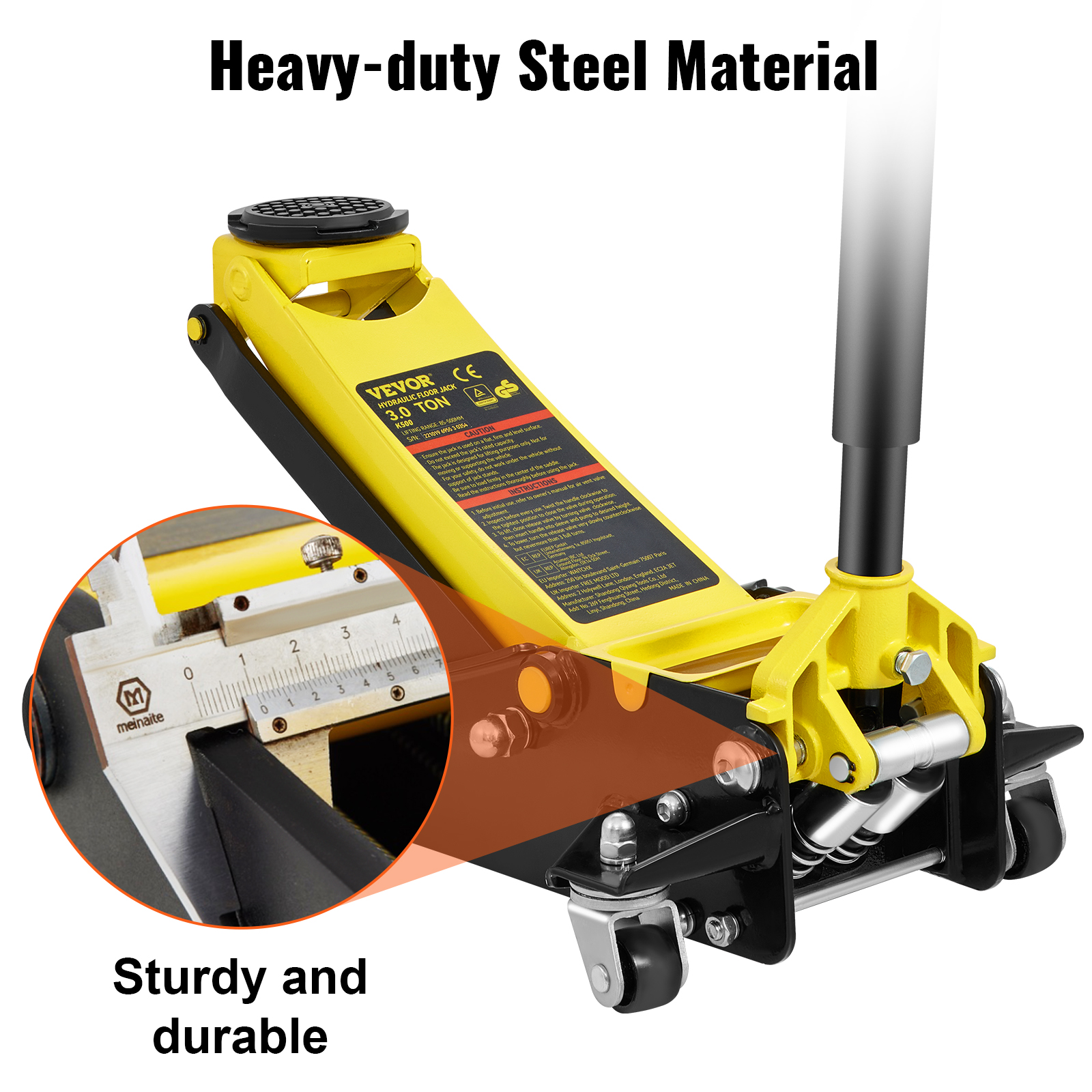
The Torin Blackjack is a low-profile floor jack that is made with heavy-duty steel. A built-in safety overload system prevents lifting beyond load capacity. We like this floor jack because it is very easy to use, rolls nicely on its casters, and is simple to assemble.
While the instructions included with the Blackjack are practically useless, it isn’t too difficult to figure out how to assemble and operate this floor jack. The handle has a comfortable grip, and the low-profile jack easily slid under our test vehicle.
The release valve is integrated into the handle, which you twist when it’s time to lower the pump’s hydraulics. Among the car jacks that we tested, the Blackjack stood out as the strongest, lifting our vehicle with the least effort on our part.
Those who like the Blackjack appreciate its heavy-duty construction and low-profile design. Many are impressed with the value given the relatively low cost of this car jack. It is easy to maneuver with a long handle.
Some people received the Blackjack with parts missing or with broken swivel casters. While this isn’t common, there are multiple complaints on Amazon about this specific issue. There are also reports that customer service is slow and difficult to contact.
This low-cost, low-profile floor jack has a lifting range up to 14.0 inches. It has a 3.5-inch clearance, making it suitable for low-riding vehicles. A built-in safety valve prevents over-pumping and overloading this car jack. We like it for the price and ease of operation.
The F-767 is not as ruggedly built as the Torin Blackjack. However, it is made from alloy steel construction and is generally easy to use. The lever design offers an easy way to raise your vehicle, and this device is ultra low profile (just under 4.0 inches).
Users with low-riding cars especially seem to appreciate this car jack, which is able to neatly slide under such vehicles. The majority of reviews are comments from those who were happy to report that the jack works as advertised with no issues.
There are reviewers who say that they were shipped jacks with missing parts. This appears to be rare, but it can be very annoying if it happens to you. Some also say that it is a little short, and would prefer a jack able to raise their car higher.
The Blackhawk B6350 is a beefy car jack with a weight limit of 3.5 tons for larger vehicles. This steel floor jack has a lifting range of 5.5 to 22.0 inches and built-in safety valves for overload protection. It features an extra-long handle for greater leverage and is the most powerful car jack that we tested.
Operating this hydraulic jack is similar to the other floor jacks that we tested – insert the handle, tighten the release valve, and pump. The included instructions are easy to follow. Generally, we were impressed with the construction and material quality of this car jack. The handle is very long which makes operation easier, and it is covered in a comfortable foam. It has a fast lift speed and is made of high-quality materials.
Though quite heavy, this jack isn’t difficult to maneuver on its wheels. It does take two people to lift, however. This is the least portable jack we tested.
Most are impressed with the high load weight offered by this relatively inexpensive car jack. According to customer reviews, this is a long-lasting jack.
Some have reported poor welds on the handle, which broke for a handful of customers. Aside from that item, the jack is well-constructed. It may ship low on hydraulic fluid (and need to be topped off), but most are satisfied with a jack that can lift 3.5-ton vehicles at this price. The Blackhawk seems to be an especially popular jack for DIY mechanics.
This tiny bottle jack has a 10.0-ton lift capacity (6.0-, 8.0-, 12.0-, 30.0-, and 50.0-ton versions are also available). It can lift vehicles up to 18.13 inches and comes with a one-year warranty. This bottle jack’s small size makes it highly portable, but the design means that it won’t fit under vehicles with low clearance. It did not fit under our first test vehicle (a sedan), so we tested it on an SUV with a higher chassis.
The Big Red hydraulic bottle jack is easy to carry and position, weighing only around 10.7 pounds in total. When first using this jack you must follow the instructions to remove excess air and possibly top up the hydraulic fluid.
The lever is shorter than with floor jacks and doesn’t include a comfortable handle. It also fits together awkwardly – one part slides into the pinched end of the other, and rests that way, somewhat wobbly.
Besides positioning, this jack is harder to use than the standard floor jack, but still not difficult. It has a very high load capacity (10.0 tons) and easily raised the test vehicle.
Many write that this is an excellent option for high-clearance, heavy vehicles. It has a high weight capacity and its portability makes it a popular choice for changing spares. Be sure that it is stored upright, however, as bottle jacks can leak fluid otherwise.
Some have complained about receiving jacks that leak fluid. In the worst case, a few people got packages wet with hydraulic fluid. It’s annoying to need to clean and maintain your new product, but given the shipping distances, this isn’t entirely unreasonable.
The Big Red floor jack is a good low-cost option for a strong car jack. This jack has a maximum lift height of 20.88 inches. It uses a single-piston quick lift pump and is designed with a safety bypass system to prevent overloading.
This car jack comes with an extra-long saddle neck which can save you some pumping when lifting raised vehicles. The neck extension can be removed for lower-clearance vehicles. We found this car jack easy to use if not quite as well-constructed as our other top picks.
What most distinguishes the Big Red floor jack from the other jacks in this review is the neck extension. This positions the jack saddle higher to begin with, meaning less pumping to lift a car. This is helpful if you have a raised car, though is not necessary for low-profile vehicles like our test car.
This car jack is as easy to operate as any well-designed floor jack. However, the handle design doesn’t seem as sturdy or as comfortable as the Blackjack or F-767. Still, we were able to raise and lower our test vehicle with ease using this floor jack.
Happy reviewers like how this jack works, and many mention the extended saddle neck as an appreciated convenience. Several report years of reliable use from this car jack, which is easy to maneuver and pump.
There are some comments about faulty welding on the wheels. Though uncommon, more than one reviewer posted complaints about the wheels failing. Another typical criticism is that the jack lowers too quickly. Some write that when the pressure valve is released the jack falls down very quickly. We did not experience this when we tested the Big Red floor jack, but this issue may be more common with heavier vehicles.
Scissor jacks are accordion-looking contraptions found with many spare tire kits. These jacks use a screw mechanism to raise your vehicle. They are slow and can be difficult to use.
Floor jacks are large and heavy, but stable and easy to use (if more difficult to maneuver). These are the most common type of jack for a garage or workshop.
Bottle jacks are small and bottle-shaped. These often operate with a lever and are easy to use, but can’t lift as high as a floor jack. A bottle jack is a good option for a portable jack but a poor choice for a car with low clearance.
When selecting a jack, you need to pick something that will fit underneath your vehicle before you begin to lift it. Some sports cars and luxury vehicles have especially low clearances, so require a low-profile jack to elevate. When purchasing a jack, consider your vehicle’s clearance compared to the jack’s.
Also, consider a car jack’s maximum lift height. If you have an especially high vehicle like an SUV, smaller jacks may not raise high enough to hoist your car off the ground.
Any car jack is rated to lift a certain tonnage. If you’re buying a car jack to lift your vehicle for repairs, pick something with a weight rating to match the vehicle you’re trying to lift. Keep in mind that to change a tire, you’ll only need to lift half the weight of the vehicle. You should be able to find your vehicle’s weight on the door panel or owner’s manual. The typical sedan weighs around 3,000.0 pounds, while trucks can weigh around 8,000.0 pounds.
How you plan to use your car jack should determine which type of jack you get. If you want to raise your car so you can get under the body to tinker around, you’ll most likely want a floor jack. These are the most stable and provide the best lifting power.
Floor jacks can be large and heavy, so they aren’t reasonable to carry in your trunk at all times, should you get a flat. If you need a car jack for spare tires, a scissor jack or bottle jack will serve you better (keep in mind vehicle clearance if you get a bottle jack, which may not fit under your car unless you have a truck or SUV).
If you need to jack up your vehicle, a floor jack is typically the universal choice for its ability to lift vehicles higher than a bottle jack. Most vehicles also come with a scissor jack that can support the weight of your vehicle but may not be compatible with other car models.
You don’t need to be a professional mechanic to use a car jack, and many jacks are simple to operate. However, there are some steps you’ll want to consider to keep yourself and your car safe. Additionally, drivingtests.org has a detailed guide should our instructions here not suffice.
Before raising your car, you should also have jack stands and wheel chocks. Jack stands support and stabilize your car after it’s been lifted. They are a crucial safety component if you plan to work under your car while it is elevated. Any jack, especially a hydraulic jack, can fail and if that happens jack stands will prevent you from being crushed. Wheel chocks stop your car from rolling while it is elevated.
Before lifting your car from the ground with a car jack, make sure that it is on a level surface, in park, with the engine off, and the emergency brake engaged. If you have wheel chocks, place those behind your wheels.
You don’t want to place the jack just anywhere before lifting your car. If you put it in the wrong spot it can damage your trim or undercarriage. Consult your owner’s manual to find the jack points – typically a reinforced metal plate just behind each front wheel and just in front of each back wheel.
Slide the car jack under your vehicle and start lifting. If you’re using jack stands, set those up once your car has been raised and before you get to work.
Hydraulic floor jacks often need maintenance, sometimes even when new. Before using your jack, be sure to inspect the welds and bolts. Make sure there are no cracks and that every screw is fully tightened. If your car jack isn’t lifting properly it may need bleeding, a fluid top-off, or both.
New car jacks typically don’t need oil replacement for at least a year. However, if the screw or cap covering the oil chamber is loosened or damaged during shipping, your car jack could arrive low on hydraulic fluid.
To determine if your jack is low on fluid, open the oil chamber and inspect the fluid levels. Hydraulic fluid should come up to 1/8 of an inch from the top of the chamber. If you can’t see any oil, you’ll need to add more.
A floor jack like the Torin Blackjack will offer the fastest lifting speed and most stability. However, these jacks are heavy and not something you can store in your trunk for emergencies. For changing a tire, you’ll need a bottle jack like the Big Red Bottle Jack or a scissor jack.
Regardless of which car jack you have, be sure to also use safety equipment like wheel chocks and jack stands. You may not need jack stands just to change a tire, but you should certainly use them if you plan on sliding underneath a raised vehicle.
The automotive jacks in this article went through two rounds of reviews. We started by searching Amazon for top products, looking at customer ratings, Amazon superlatives, and prices. We combed through customer reviews to find a variety of jacks that are consistently rated for quality, durability, and value.
The car jacks that best met these standards were ordered by our team for testing. A team member assembled and tested each jack on a car, lifting it several inches off the ground. Each car jack was given a rating out of 5 stars based on ease of use, durability, and value.
To test each car jack, we unboxed and assembled the jacks according to the instructions (if any were included). We placed each jack under the test vehicle and lifted it several inches off the ground. Our tester was able to note the quality of materials, ease of use, and overall performance.
Based on our testing, we think that Torin, Pro-Lift, Blackhawk, and Big Red are all excellent brands for car jacks. Many car jacks are sold by different companies but manufactured by the same factory, so in some cases, it may be worth buying whichever is cheapest.
Never get under a car that is supported exclusively by a car jack. Even the safest car jack isn’t safe enough to hold a car on its own. While all of the car jacks we recommend (Torin Blackjack, Pro-Lift F-767 Blackhawk B6350, Big Red floor jack, and Big Red bottle jack) are excellent car jacks, you should always place your car on jack stands when working underneath.
Car jacks are reliable for lifting your vehicle, changing tires, or doing work under the chassis. However, no car jack is reliable enough that you should trust it with your life. Whenever working underneath a car be sure to support the vehicle with jack stands and not your jack’s lift arm alone.
A 3.0-ton jack can safely lift up to around 3,500.0 pounds. If the thing you’re lifting is significantly lighter than that, you may not need a 3.0-ton jack. If the thing you’re lifting weighs more than 3,500.0 pounds, you’ll need a stronger jack.
If you’re lifting a car, keep in mind you may only need to lift one side of the vehicle, so if your car weighs 7,000.0 pounds, a 3.0-ton floor jack can raise it enough to change a flat tire or perform oil changes.
A 2.0-ton floor jack can lift vehicles up to around 2,400.0 pounds. This will lift some SUVs, but the typical mid-size SUV can weigh up to 5,000.0 pounds. However, when using a jack, you’re likely only lifting one side of the vehicle, and not the entire car’s weight.
Professional mechanics generally use hydraulic jacks since they can bear the entire weight of a vehicle and allow greater access to work on a variety of issues.
The best car jack stands are best suited for specific maintenance tasks like replacing tires, changing brakes, or working on the underbelly of the vehicle. In other cases, ramps are cheaper and typically safer.

This is a 1 1/4 ton hydraulic floor jack my father passed on to me. He bought it new during the 1970s. It began to leak down a little a few months ago. The lift arm no longer rises when the handle is pumped up and down. (I was able to pull the lift arm up by hand and it settled slowly enough that I could make a photo with the arm partially raised.)
I checked to be sure it was adequately filled with fluid, but that was not the problem. A few months before this problem, there were bubbles coming up through the vents at the filler plug. At that time I raised the lift arm with the handle, released the jack"s valve, and let the arm fall slowly several times to purge air from the system. Finally, one day, the lift arm would not rise at all. If filling with fluid and purging air from the system do not restore function, there is probably internal leakage, even though fluid is not leaking from the jack. From what I have read, forty years of service is a reasonable time for a hydraulic jack to operate before it needs a rebuild.
A word of caution: Rebuilding this jack presented several challenges that seemed almost insurmountable at the occurrence of each. Rebuilding this jack was much more difficult than simply replacing a few "O" rings, and it required more than the very few hours some say are required for rebuilding a jack. Further, I had to make several special tools to get the job done. If you want to attempt rebuilding a jack and you are not a member of Instructables, I would encourage you to pick a password and a screenname, and join. Doing that will allow you to download a PDF of this Instructable for printing, or to view at any time later on your computer, assuming you wish to consult what I have done as a guide.
When putting fluid into a jack never use anything other than hydraulic jack fluid. Do not use motor oil or brake fluid. Brake fluid makes the seals swell.
At this link you will find one man"s description of how he rejuvenated his twenty-five year old jack by flushing its insides with a solvent, letting it dry completely, and filling it with fresh hydraulic jack fluid. It could be worth a try. I did find one manual for a floor jack that said the fluid should be changed every year. The procedure is to place the jack over a large pan, remove the filler plug, turn the jack on its side and let it drain. Then fill it again.
Several firms sell rebuild kits for hydraulic jacks. I found Blackhawk Parts and ordered parts on-line. My jack came with the Fleet brand name. It was sold through NAPA Auto Parts. It should have been easy to find my jack among the listings for Fleet jacks on the Blackhawk Parts web page and order the appropriate rebuild kit, but it was not. So, I sent an e-mail to Blackhawk Parts with the name of the manufacturer and the model number. It is good that I did. The kit I need is not the one I would have thought, but is actually for a Lincoln/Walker jack. Although my jack has the Fleet name, it was actually made by someone else. I paid about $45 for the parts kit, plus $11 shipping. That is a fairly typical price for a rebuild kit.
I decided not to open the parts kit until I was certain the parts it contains match what I see on my jack as I dismantle it. I will have less difficulty exchanging an unopened parts kit than I would have trying to exchange a kit I had opened, in case the wrong one was shipped to me. In the photo you can also see the paperwork that came with the parts kit. It will help, too, if an exchange were necessary. And, I do not want to risk losing any parts by opening the bag early and having something roll out.
The rebuild kit does not include any instructions. The Blackhawk Parts web page offers a few cautionary and a few safety notes, but no helps on the rebuild procedure for the Saturday mechanic. e-How does offer a step-by-step procedure for rebuilding a hydraulic jack in text, but it is quite general. There is avery helpful link at the e-How page that takes you to a set of photos and some useful notes on critical stages for doing work on a low price imported hydraulic floor jack. Some of these things would be very helpful for the proper assembly, too. Floor jacks are remarkably similar, despite small differences. See the next step for information on helpful videos on-line.
The graphic for this step is an exploded diagram of a hydraulic jack and a list of parts. This one is from aHarbor Freight jack. Diagrams like this one are easy to find on the Internet. Just search for "hydraulic jack manual." Diagrams like this one help with the names of parts and with a visual understanding of how the parts fit together. You can enlarge images in your browser to see more detail, or save them in PDF and do the same. But, if you are able to watch the videos linked in step 3, you will see how the parts fit together, too. (The day may come when those videos are no longer available on the Internet.)
There are many videos related to hydraulic jacks at YouTube, but most of those are not really very helpful for a rebuild, even though their titles are enticing. A floor jack is a really a bottle jack laid over onto its side and installed inside a frame equipped with casters, a handle, and a lift arm. This video shows how to remove the bottle jack unit from the frame. The floor jack in the video is my Fleet jack with a different name and paint color on it. Some jacks are the least bit different. You may also want to view this video.
If you do not want to rebuild the bottle jack unit yourself, you can use either of these videos to remove the bottle jack unit from the frame of the jack and simply take it to a repair shop near you. The cost of a rebuild at a shop is said to be around $150 to $200 plus parts. The e-How article linked in step 2 contains a word of caution. If your jack is a cheap import, it may not be worth a rebuild. The machining is not always as good as on the older models made in the USA. Further, the correct parts kit may be impossible to get. You may find it more economical simply to buy a new jack. Classic jacks made in the USA are generally considered worth the expense and effort of a rebuild.
First photo--The halves of the jack frame will need to be spread to get the bottle jack unit out for repair. Loosen the nuts on the axle for the lift arm considerably, but do not remove them. There is one on each side of the jack frame. The nuts on my jack are 15/16 inch in size.
Second photo--Two bolts on each side hold the body of the bottle jack unit to the frame. Remove all four. (One is partially backed out already.) Although the man in the video from step 3 removed the casters, that is not really necessary to access the bolts on this jack. I did fine without removing the casters.
Fourth photo--A universal joint twists to open and close the release valve. The upper end of the universal joint is a piece of hex stock. It fits into a hex socket in the bottom of the handle.
Fifth photo--Lift the jack frame and the bottle jack unit remains on the work surface, even though attached to the lift arm by hinged extensions. Use a pair of pliers to remove the end of the return spring from the pin.
Sixth photo--The rams from the jacks shown in the videos attach to the frame with a cotter pin. On this jack a pin both holds the end of the spring and secures the block in the photo to the top end of the ram. Flip the bottle jack unit over and drive the pin most of the way out with a hammer and a punch.
Place the bottle jack unit into a pan and drain the oil as best you can. On the bottle jack unit in one of the videos it was easy to work the plunger in order to extract more of the oil. The spring on the plunger is too strong for that on this jack. Be aware that additional oil will pour out of the jack in coming steps. Have a pan or newspaper available to catch it and minimize the mess.
The first photo shows the ram and ram nut (or tank nut, also top nut) at the end of the bottle jack. Most ram nuts are hexagonal. This one has two slots for a special spanner wrench. In the video from step 3 showing a man taking the ram nut off of a bottle jack, the ram nut came loose quite easily. On my jack the nut was stuck on very hard. I placed the bottle jack unit into my vise and tried to loosen the ram nut with a very large pipe wrench. I only did a little cosmetic damage to the nut. It would not loosen. I soon realized that my workbench and vise were not equal to the task, either.
The third photo shows the tool in use. Check the yellow text boxes. My vise did not have enough leverage to hold the bottle jack unit, so I bolted it upright into the jack frame and used the jack frame as my own long bar for leverage. In order to make that work, I planted my foot against the end of the frame that is not shown in the photo. I had to strike very hard with a 16 ounce ball peen hammer, but after about five or six strikes, the ram nut began to move. My tool worked and I was able to loosen the ram nut with the ram for removal from the bottle jack unit.
First photo--Unscrew the ram nut until it and the ram can be pulled from the bottle jack unit. The ram nut simply pulls off of the top end of the ram.
The outer shell of the oil tank appears to be securely fastened to the base of the bottle jack unit, but it is not. Press against its side and it tips off to one side immediately. There will be some oil that runs out onto the work surface. Put down some newspaper or a pan to catch it.
Third photo--Unscrew the universal joint assembly for the release valve. Insert a magnetic tool and pull out the cone-shaped plug. The hole from which it came is visible behind the magnet tool.
Fourth photo--Place the bottle jack unit in a vise and use a wrench to remove the plunger mechanism. I had to tap on the end of the wrench with a hammer to loosen it. On my jack a 1 inch wrench was required.
Move your cursor over the text boxes in the first photo. for part names, etc. The cylinder would normally be removed for a rebuild. But, this one is stuck very tightly. Remember how much difficulty there was in removing the ram nut in step 6. It screws to the cylinder, so the cylinder should be difficult to remove, too. It is not as easy as the video linked in step 3. I tried, but could not get it to loosen. There actually are no "O" rings or seals below the cylinder on this jack. Removing it does not give access to any removable parts. I did notice some oil at the bottom of the cylinder appears dirty.
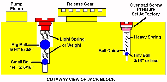
There are two metal plugs in the body of the bottle jack unit. Two large screws are below them. See the text boxes again. This site warns NEVER EVER to open these. It also has a diagram of what is inside. (Scroll down to the middle of the web page.) The author"s concern is that the small balls in the valves can be lost, and the jack would become useless. Get a shallow cardboard box with no holes in the bottom or a large pan and work inside of either one. If any balls roll away, they will be contained inside the box or the pan. Also, extra balls are included in my kit. Even if the balls were not included in the kit, precision steel balls can be purchased at a bicycle shop in a series of sizes. Check the link in this paragraph for the sizes normally used. The ball sizes in my jack are: 5/16 inch (7.94mm), 7/32 inch (5.55mm), and 5/32 inch (3.96mm). I measured them with a caliper through the plastic parts bag. I want to do as complete a rebuild as possible. Dirt may have found its way into the passageways where the balls are. The balls could also have rough surfaces through years of use.
If I turn the jack body back and forth I can hear metal balls rolling inside passageways. I drilled a hole in the center of each of the metal plugs. Then I inserted a slightly larger sheet metal screw into the hole until the threads bound against the hole I drilled. I placed a pair of pliers under the head of the screw and pounded against the pliers with a hammer to pull the metal plug out of the jack"s body. I repeated the process with the other plug. New plugs are included in the parts kit.
The second photo shows the bottle jack unit"s body, but inverted so it was easier to hold while operating the camera. The metal plugs have been removed. Both holes have a large screw inside them. The one on the right is recessed so far that it is not visible. It is the safety overload valve. This valve protects the jack"s seals from failing under a load heavier than the jack"s rating. When the safe range of the jack is exceeded, the safety overload valve opens like a pressure regulator to allow oil to return to the tank rather than entering the chamber for the ram. This screw has to be set so the safe level of pressure is not exceeded. In order to do that at home, I carefully turned this screw and counted by half-turns until it bottomed out. My screw was set to 1 3/4 turns above or looser than the bottoming out point. When it is time for reassembly, I will turn the screw gently until it bottoms out, then I will back it off 1 3/4 turns. The safety overload valve should then be set very close to the original factory calibration. One author noted that some jacks fail because the safety overload screw unscrews itself, which sets the jack"s lifting ability to a much lower threshold, and the arm may not lift what you want to jack. I found this screw turned with enough resistance that it is not likely to shift its position by itself. That same author also said most safety overload screws are about two turns looser than the bottoming out point.
The fourth photoshows another special tool I made. The screw for the check valves is quite tight. I tried the largest screwdriver I had (3/8 inch wide blade) with a wrench on its square shank. The blade on the screwdriver broke! The screw slot is 1/2 inch across the diameter of the screw and almost 1/8 inch wide. I bought a short bolt 5/8 inch in diameter. It is #8 on the hardness scale. Near the end I ground the diameter down until it fit nicely inside the recess for the screw. I kept a cup of cold water near my grinding wheel to avoid softening the bolt with heat. I ground a rough profile by sight. I moved the bolt to a vise and finished cutting the profile of the screw slot by means of a hand file. I checked the dimensions with a digital caliper. When my improvised screwdriver fit the screw and its slot, I tapped on the bolt"s head to be certain it had fully seated in the slot. I used a wrench on the bolt head and the screw came out with no difficulty, at all. I had tried to buy a large screwdriver, but could find none this large. This improvised solution cost me $1.65 for the bolt and a few minutes of time.
The first photo shows a paper towel I pressed into the cylinder and rotated with a screwdriver without letting the screwdriver touch the sides of the cylinder. (Be careful not to scratch the inside of the cylinder. A 1/2 inch dowel pin would have been a safer tool to use.) Jack fluid is clear. The towel shows how much dirt was in my jack"s oil. In addition to sopping up some dirty oil still in the cylinder, I poured a little clean jack oil into the openings and passageways. Most of it collected in the opening for the plunger. At first this oil was cloudy. After a few tries, it was clear. I think this should adequately clean the jack so that it can be reassembled.
Inspect the seats in the bottle jack unit"s body for signs of rust and pitting. The seats need to be clean and smooth. When I let sunlight shine into the recesses where there are seats, I saw more dirt. I used a wooden dowel rod to scrape and break loose any dirt I could find. I poured some jack oil into the holes to flush the dirt away.
Second photo--Clean the groove that receives the tank"s outer shell. It has some brown dried oil residue. Something brass would be ideal. It would be tough enough to remove the residue, but would not scratch the machined surface. Someone said jack oil is a vegetable oil. The oil residue is certainly like what I have seen in the kitchen from vegetable oils.
I kept the bag of parts inside the same shallow pan in which I assembled the bottle jack unit. This is so I am less likely to lose parts, especially the steel balls.
First photo--This shows the plunger body and the plunger parts. At the left three leather seals are shown. My jack does not use these. Several different parts came in more than one version. I think the same parts kit is sold for several similar, but different jacks. I have some parts I will not use on my jack. In the center area of the parts are the steel washer and the locking nut. The other two parts at the right are the old seal I removed. It has an oily sheen. Just below it is the replacement part my jack requires.
Second photo--Coat the new neoprene seal with fresh jack oil. During the installation of all parts, double check for any grit or dirt sticking to the oily parts and remove it before the installation of that part. Install the new neoprene seal, rounded end first. Install the steel washer and the locking nut. I will discuss how tight to tighten the locking nut after treating how to install the spring assembly onto the plunger body. I made a special tool for putting the plunger assembly back together. It is made from steel wire about 1/8 inch in diameter. The wire came from stubs of concrete reinforcement wire broken off from a friend"s foundation for his new garage.
The third photo shows how this special tool is used. I chucked this tool in my small drill press. The circle of wire at the end of the tool fits over the top of the cap for the plunger assembly. The two straight pieces welded crosswise allow the quill of the drill press to exert pressure downward and to collapse the spring so the "C" ring can be attached. Notice that the bottom end of the plunger body presses against wood so the smooth machined surface is not scratched. I used an adjustable pliers to close the "C" ring. My drill press has limited adjustment. I used a couple of pieces of wood on the drill"s base in order to achieve the desired distance between the chuck and the surface supporting the smooth end of the plunger.
Check the plunger for dust and particles of wood. Thread the plunger into the base of the bottle jack unit. Tighten with a wrench and hit the wrench several times with a hammer to make a good seal, since there is no "O" ring or copper washer to make the seal.
First photo--I have a dental pick I can use to remove old seals. This "O" ring shows cracks from age when stretched a little. Match the new "O" ring from the parts kit to the old "O" ring. Coat it with jack oil. Install the new "O" ring.
Second photo--Install the conical metal seal in the hole for the release valve. The pointed end goes in first. Tamp on it with a small screwdriver to make sure it seats at the bottom of the hole. Thread the release valve into the hole.
First photo--The hole for the check valves has a copper sealing washer inside it. The old washer is barely visible in the hole. Note its color. A new copper washer is supplied in the parts kit. The old washer has compressed to fit very tightly. There is no good way to remove it. I did not want to fill the passageways in my jack with copper shavings from digging it out in pieces. I decided simply to place the new washer on top of what is left of the old washer. (This photo was made before the plunger and the release valve were installed.)
Second photo--Install the parts in the order shown in this photo from step 8. (The release valve and the plunger are not shown in this photo.) Use the new balls from the parts kit. Do all of this inside a pan or shallow cardboard box so none of the balls are lost if one gets away from you. Tamp the parts down with a small screwdriver so they settle down as far as possible in their hole. Carefully start the screw plug with a screwdriver. It is easy to crossthread. Use the special screwdriver made from a hardened bolt to tighten the screw plug with a wrench.
Third photo--Install the parts shown in this photo from step 8. Drop the new ball into the hole. Insert the spring into the open end of the cap and drop both into the hole. Insert the screw plug. Carefully turn the screw plug until the valve assembly bottoms out. Back it off 1 3/4 turns.
I chose not to install the metal plugs that close the valve holes yet in case I would need to open one of the valves during testing of the jack to correct a problem.
Coat the inside of the cylinder with jack oil before inserting the ram. You should be able to pull the ram up and push it down with your hand. A seal too large in size makes the ram very difficult to install and to move.
Second photo--Clean the tank shell, both on the edges that mate to make a seal and inside. I found quite a bit of dirt inside mine. The dirt had not entered the jack from the outside, but appeared to be residue that had formed from changes in the oil. I applied some jack oil to the inside of the tank and wiped it with a clean paper towel. I did this several times until I could no longer feel anything gritty with my fingertips.
Retrace what you did in step 4, but in reverse, to bolt the bottle jack unit back into the jack"s frame. (The photo is from that step.) While the bolts are still loose, put the handle"s yoke in place.
I used about 20 ounces of jack fluid. Around 12 ounces was used to fill the jack. The rest was used for cleaning and flushing the bottle jack unit. The fill hole is 1/4 inch in diameter. Even though the bottles for the jack oil have a pointed end, some spurts out while trying to get the bottle end to the hole, and it makes a mess. Get a funnel with a very narrow end. This is one I made specifically for this job from some sheet metal.
I filled the reservoir in small steps. The jack"s release valve was open. Occasionally I pumped the yoke for the handle. When oil was at the level below the plug hole, I pulled the lift arm up and let it fall two or three times. This is to draw oil through the jack. I pumped the yoke between five and ten times to remove any air lock in the check valves. I checked the oil level again a couple of times. Then I returned the reservoir cap. The reservoir cap appears to be open, but actually has a small felt filter inside it.
Update: After using my jack a few times, it tends to throw off extra oil through the felt filter in the reservoir cap. I do not have the original instructions for this jack, so I do not know exactly what the recommended fill level is for it. From what I have read, some jacks are to be filled to the bottom of the hole while the floor jack is level on a floor. Others vary between just covering the cylinder with oil to slightly below the fill hole. At first I thought I might have a leak, but it was just the jack throwing off extra oil. This extra oil may also be due to the jack evacuating air trapped inside the jack. There are bubbles in the oil vented. One source suggested raising the jack fully and lowering it slowly twenty or so times to remove all air that might be trapped inside the jack"s passageways. Check the oil level to keep it at the desired level.
My jack worked as it should immediately. The real test is to lift something heavy with the jack. I left the jack in this position for a few minutes. It did not leak down that I could see. Now I can use a hammer to tap the metal caps into the holes for the safety overload valve and for the check valves. I will check the fluid level again after I have used the jack several times. I will also watch for signs of leakage. It is also a good idea to oil or grease all moving parts on the jack now and regularly in the future.
Troubleshooting--What do you do if you have rebuilt your jack, but it still does not work under load? Be certain the oil level is correct. Here are instructionson properly filling a floor jack. The jack could be air locked. This site says to open the release valve and pump the handle rapidly 10 to 15 times in that case. Here is a link to a document on troubleshooting hydraulic systems, like a jack. If necessary, check to be certain all check valve balls were installed properly. Check for leaks.
Conclusions--I did not find any clearly damaged seals in my jack, other than cracks in an "O" ring on part of the release valve, but it was a non-critical part. I did find dirt in the oil. I expect the seals were just old and less efficient. It feels good to have my jack working again, especially since it once belonged to my father. Rebuilding a hydraulic floor jack was much more difficult and a lot more work than I expected from information I had gathered before I began. I found some parts were not as easy to remove as I expected from videos and other helps that I linked earlier in this Instructable, and I had to make several special tools. I first had to develop those in my mind. Then I had to design them and build them with materials I already had. Fortunately, I have a welder and was able to do that without too much difficulty.
I can easily understand why many suggest a person ought simply buy a cheap jack and replace it with another when it fails. I have a hard time doing that, no matter how much financial sense it might make, That seems like the waste of a good tool containing numerous carefully machined parts. An imported floor jack comparable in capacity to mine lists for around twice the cost of the parts kit I bought, sometimes even less than twice the cost of the parts kit. I do not know if my Fleet jack will last longer than an import jack.
Knowing all I know now, I might suggest flushing out old jack oil every decade and replacing it with fresh, clean fluid. Even then, I am not sure draining the old fluid and refilling the jack with new fluid would have removed all of the dirt I found. Some of it was in places that seemed to hold the dirty oil in that particular place. The oil in the reservoir had always appeared clear and clean. Still, neoprene seals used in hydraulic jacks do harden or crack and will fail to seal properly in time.
Owning and using a hydraulic jack is often a necessity. But, it has costs over time. Those costs mean the eventual repair or replacement of a jack. If you choose to repair your jack, you have the option of doing it yourself or of taking it to a shop. If you choose to do it yourself, you will learn a lot, but it may require more of your time and be more difficult than you expected. If you take it to a shop, there will be a cash outlay that will likely be a fair amount greater than the cost of a new imported jack.
Several times I feared I had ruined a vital part on my jack, or was about to do so, simply because I was without knowledge and experience related to rebuilding a floor jack. It is my hope that this Instructable will enable others who wish to do so to rebuild a hydraulic jack with confidence and without some of the near mishaps I experienced. I wish someone had published this before I began to rebuild my jack. It would have saved me time and trouble.
Thank you. That is what I expected you have. I suppose you could also try to collect names of jacks using those gesrs and inquire of them to see if the gears are available as replacement parts.0
My CRAFTSMAN floor jack has 3 ports (valves)..... could you tell me what each one is and how to set them ? It was made around 2005...... (MADE IN CHINA) model #214.50145
I rebuilt this with new parts no problem...... I just did NOT check the turns for the check valve and safety overload valve and a 3rd one ??? ( factory settings)


 8613371530291