
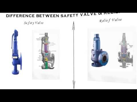
give the difference between safety valve and relief valve for sale

As you already know, there are a multitude of pressure relief valves out there. In the industry, we tend to use terms like safety valve and relief valve interchangeably. And for the most part, this makes sense. Most pressure relief valves are designed to do the same thing — release pressure in a system.
But is there a difference between some of these commonly used terms, and if so, what does it mean for you? Here’s a quick breakdown of two popular terms: safety valve vs. relief valve.
While both terms refer to valves used to release pressure from a pressurized system, their technical definitions are a bit different. In general, the term relief valve refers to a valve within a pressurized system that is used to control pressure for the optimal functionality of the system. Relief valves are designed to help your facility avoid system failures, and protect equipment from overpressurized conditions.
The term safety valve, on the other hand, refers to pressure valves that are designed to protect people, property, and processes. In other words, the term safety valve refers to a failsafe, last resort valve that will release pressure to prevent a catastrophe, usually in the event that all other relief valves have failed to adequately control pressure within a system.
The general purpose of both safety valves and relief valves are the same. Both are pressure relief valves, and they are designed to let off pressure in any situation where a system becomes overpressurized. That said, relief valves and safety valves do function slightly differently:
Relief Valves are designed to control pressure in a system, most often in fluid or compressed air systems. These valves open in proportion to the increase in system pressure. This means they don’t fly all the way open when the system is slightly overpressure. Instead, they open gradually, allowing the system to return to the preset pressure level. When that level is reached, the valve shuts again.
Safety Valves are used for one reason — safety. Instead of controlling the pressure in a system, they’re designed to immediately release pressure in the event of an emergency or system failure. Unlike relief valves, safety valves open immediately and completely to avoid a disaster, rather than to control the pressure of a system.
While both safety valves and relief valves work to release excess pressure, the way they go about it is a little different. Check out this table, courtesy of Difference Between, for a little more information about the differences between the two valves:

Both the terms are used interchangeably in the process industry as every pressurized system requires safety devices to protect life, property, and environment. Relief valves and safety valves are the two principle safety devices designed to prevent overpressure conditions in process industries. Although, both the devices are used almost for the same purpose, the difference lies mainly in how they operate.
Relief valves, or commonly known as pressure relief valves (PRVs), belong to the family of protective devices specifically designed to protect pressure-sensitive systems and equipment from the damaging effects of overpressure conditions. A relief valve device is basically immune to the back pressure effects of a system and is subject to periodic stripdown. Pressure relief valves are one of the most critical parts of a pressure system that are set to open at a preset pressure level in order to avoid system failures. Every pressure system is set with a predetermined design limit called a setpoint, above which the valve begins to open to prevent overpressure conditions.
A safety valve is the last resort of people, property, and processes in the process industry comprising of power plants, petrochemicals, boilers, oil and gas, pharmaceuticals, and many more. It’s kind of a fail-safe device that actuates automatically in order to prevent the accumulation of pressure in a vessel or system beyond a preset limit. The device is so designed so that the safety valve trips automatically when the given pressure is attained. It simply allows the excess pressure to escape in order to prevent any damage to the vessel. Additionally, it also makes sure the pressure remains within the limits in the future. Even a slight increment in pressure lifts the safety valve and it closes as soon as the pressure is reduced to the prescribed limit.
A relief valve, also known as pressure relief valve (PRV) or safety relief valve, is type of a safety valve device used to limit or control the pressure level in a system within a safe threshold limit to avoid an overpressure condition. In simple terms, a relief valve is a device designed to control the pressure in a vessel or system to a specific set level. A safety valve, on the other hand, is a device used to let go excess pressure from a vessel or equipment when the pressure crosses a certain predetermined limit. It simply allows liquids or gases to escape if the pressure gets too high to prevent any damage.
Pressure relief valves are mainly used in hydraulic systems to limit the pressure in the system to a specific preset level and when the pressure reaches the safety design limit, the relief valve responds by releasing the excess flow from an auxiliary passage from the system back to the tank in order to prevent equipment failure. The main purpose of a safety valve is to protect life, property, and environment against failure in the control system pressure. Simply put, a safety valve opens when the pressure exceeds the designed set pressure limit.
For a safety relief valve, the opening is directly proportional to the increase in the vessel pressure. This means the opening of the valve is rather gradual than sudden, allowing it to open only at a preset pressure level and release fluids until the pressure drops to the desired set pressure. A safety valve, on the other hand, will open immediately when the system pressure reaches the set pressure level in order to system failure. It is safety device capable of operating at all times and is the last resort to prevent catastrophic failure in systems under overpressure conditions.
A pressure relief valve is designed to open at a certain pressure level which is generally called as a “setpoint”. A setpoint should not be confused with the set pressure. In fact, a setpoint of a relief valves is adjusted to the lowest maximum pressure rating meaning it is set below the maximum system pressure allowed before the overpressure condition occurs. The valve begins to open when the pressure reaches up to some level above the setpoint. The setpoint is measured in pounds per square inch (PSIG) and must not exceed the maximum allowable working pressure (MAWP). In safety valves, the setpoint is usually set at 3 percent above the working pressure level whereas in relief valves, it is set at 10 percent.
Both relief valves and safety valves are high-performance pressure-sensitive safety devices so designed to control or limit the pressure inside the system or vessel by releasing the excessive pressure from the auxiliary passage out of the system. Although both are common terms used for safety valves, the difference lies mainly in the capacity and setpoint. While the former is operator-assisted and is designed to relieve pressure in order to avoid overpressure condition, the latter is a self-operated device which opens automatically when the maximum allowable pressure is reached. Relief valves are mostly used in fluid or compressed air systems, whereas safety valves are mainly used to release vapor or steam into the atmosphere.
Sagar Khillar is a prolific content/article/blog writer working as a Senior Content Developer/Writer in a reputed client services firm based in India. He has that urge to research on versatile topics and develop high-quality content to make it the best read. Thanks to his passion for writing, he has over 7 years of professional experience in writing and editing services across a wide variety of print and electronic platforms.
Outside his professional life, Sagar loves to connect with people from different cultures and origin. You can say he is curious by nature. He believes everyone is a learning experience and it brings a certain excitement, kind of a curiosity to keep going. It may feel silly at first, but it loosens you up after a while and makes it easier for you to start conversations with total strangers – that’s what he said."

This website is using a security service to protect itself from online attacks. The action you just performed triggered the security solution. There are several actions that could trigger this block including submitting a certain word or phrase, a SQL command or malformed data.

Industrial equipment often uses either safety or relief valves to prevent damaging pressure levels from building up. Though they perform similar functions, there are some critical differences between safety and relief valves. Understanding these two valves’ differences is essential for proper pressure system operation. So here we discuss the pressure safety valve vs pressure relief valve.
A pressure relief valve is a device that releases pressure from a system. The relief valve is generally immune to the effects of back pressure and must be periodically stripped down. Pressure relief valves are one the essential parts of a pressure system to prevent system failures. They are set to open at a predetermined pressure level. Each pressure system has a setpoint that is a predetermined limit. The setpoint determines when the valve will open and prevents overpressure.
Pressure relief valves are typically used in gas or liquid systems where there is a need to prevent excessive pressure from building up. When the pressure in the system reaches a certain level, the valve will open and release the pressure. Pressure relief valves are an essential safety feature in many designs and can help to prevent damage to the system or components.
PRVs are generally considered to be safe and reliable devices. However, before installing a PRV in a system, some potential disadvantages should be considered. Here are five pros and cons of pressure relief valves:
Pros: Pressure relief valves are anessential safety feature in many systems. They protect against over-pressurization by relieving excess pressure from the system. This can help to prevent severe damage or even explosions.
Pressure relief valves can help to improve the efficiency of a system. The system can operate at lower overall pressure by relieving excess pressure and saving energy.
Pressure relief valves can be used as a safety device in systems that are susceptible to overpressurization. By relieving pressure before it builds up to a dangerous level, they can help to prevent accidents and injuries.
Cons: Pressure relief valves can be a potential source of leaks. If not properly maintained, the valve may not seat properly and can allow fluids or gasses to escape.
Pressure relief valves can sometimes cause problems if they do not open or close properly. This can lead to process disruptions and may cause safety issues.
A pressure safety valve is a device used to release pressure from a system that has exceeded its design limit. This safety valve is a fail-safe device. This type of valve is typically used in systems that contain fluids or gasses under high pressure. Pressure safety valves are designed to open and release pressure when the system has exceeded its maximum pressure limit. This helps to prevent the system from rupturing or exploding.
Pressure safety valves are an essential part of many different types of systems and can help keep both people and property safe. If anyone is ever in a situation where they need to release pressure from a system, it is essential to know how to use a pressure safety valve correctly.
A pressure safety valve (PSV) is a type used to relieve a system’s pressure. PSVs are commonly used in chemical and process industries, as well as in some kinds of pressure vessels. There are both advantages and disadvantages to using a PSV. Some of the pros of using a PSV include: PSVs can help to prevent overpressurization, which can be dangerous.
A safety valve is a pressure relief device used to prevent the over-pressurization of a system. On the other hand, a relief valve is a device used to relieve pressure from a system that is already overpressurized. Function Of Pressure Relief Valve Vs Safety Valve
The function of a pressure relief valve is to protect a system or component from excess pressure. A safety valve, on the other hand, is designed to protect from overpressurization. Both types of valves are used in various industries, but each has unique benefits and drawbacks.
Pressure relief valves are typically used in systems where a small amount of overpressure can cause damage. On the other hand, safety valves are designed for systems where overpressurization could be catastrophic. Both valves have advantages and disadvantages, so choosing the right type of valve for the specific application is essential.
Relief valves are usually set to open at a specific pressure and will close once the pressure has been relieved. Safety valves are similar in that they are also used to protect equipment from excessive pressure. However, safety valves are designed to stay open until they are manually closed. This is because safety valves are typically used in applications where it is not safe to have a closed valve, such as in a gas line. Operation Of Safety Relief Valve Vs Pressure Relief Valve
Two types of valves are commonly used in industrial settings: relief valves and safety valves. Both of these valves serve essential functions, but they operate in different ways.
Relief valves are designed to relieve pressure build-up in a system. They open when the system pressure reaches a certain point, which allows excess pressure to be released. On the other hand, safety valves are designed to prevent accidents by preventing system pressure from getting too high. They open when the system pressure reaches a certain point, which allows excess pressure to be released before an accident can occur.
So, which valve is better? That depends on the situation. A relief valve is the better option to protect the system from pressure build-up. If anyone need to protect the system from accidents, then a safety valve is the better option Setpoint Of Pressure Relief Valve Vs Safety Relief Valve
The relief valve is made to open when it reaches a specific pressure, commonly described as a “setpoint”. Setpoints shouldn’t be misinterpreted as the pressure set. A setpoint on a relief valve is set to the lowest possible pressure rating, which means it is set to the lowest system pressure before an overpressure situation is observed. The valve will open as the pressure increases to a point higher than the setpoint. The setting point is determined as pounds per square inch (PSIG) and should be within the maximum allowed operating pressure (MAWP) limits. In safety valves, the setpoint is typically placed at about 3 percent over the working pressure level, whereas relief valves are determined at 10 percent.
No, the safety valve and relief valve can not be used interchangeably. Though both valves are seal butterfly valve and used for safety purposes, they serve different functions. A safety valve relieves excess pressure that builds up in a system, while a relief valve regulates the pressure in a system.
Knowing the difference between these two types of valves is essential, as using the wrong valve for the intended purpose can potentially be dangerous. If unsure which type of valve to use, it is always best to consult with a professional.
A few key points help us understand the safety valve vs pressure relief valve. Safety valves are designed to relieve pressure in a system when it gets too high, while relief valves are designed to relieve pressure when it gets too low. Safety valves are usually set to open at a specific pressure, while relief valves are generally open at a particular vacuum. Safety valves are typically intended for one-time use, while relief valves can be used multiple times. Choose the trusted valve manufactureraccording to the specific business needs.

Safety valves and relief valves have similar structure and performance, both of which discharge internal media automatically when the pressure exceeds the set value to ensure the safety of the production device. Because of this essential similarity, the two are often confused and their differences are often overlooked as they are interchangeable in some production facilities. For a clearer definition, please refer to the ASME boiler and pressure vessel specifications.
Safety Valve: An automatic pressure control device driven by the static pressure of the medium in front of the valve is used for gas or steam applications, with full open action.
The basic difference in their operating principle: The safety valve relieves the pressure into the atmosphere i.e. out of the system, it can be a pressure relief device of fluid vessels, when the set pressure value reached then the valve opens almost fully. On the contrary, relief valve relieves the pressure by relieving the fluid back into the system, that’s the low-pressure side. Relief valve opens gradually if the pressure increased gradually.
The difference is also generally shown in capacity and setpoint. A relief valve is used to relieve pressure to prevent an overpressure condition, the operator may be needed to assist in opening the valve in response to a control signal and close back once it relieves the excess pressures and continues to operate normally.
A safety valve can be used to relieve the pressure that does not need a manual reset. For example, a thermal relief valve is used to bleed off pressure in a heat exchanger if it is isolated but the possibility of thermal expansion of the fluid could cause overpressure conditions. The safety valve on a boiler or other types of fired pressure vessels must be capable of removing more energy that is possible to be put into the vessel.
In short, Safety valves and relief valves are the two most commonly used types of control valves. The safety valve belongs to the pressure release device, which can only operate when the working pressure exceeds the allowable range to protect the system. The relief valve can make the high-pressure medium quickly to meet the pressure requirements of the system and its working process is continuous.
Thus, its operation is automatic; it will open only to release the pressure and not exceed the liquid force; therefore, its use is more common with fluids (although, they can also be used with vapours or moderate gases). In terms of capacity, they can withstand low pressures and their processes are continuous.
Whenever a gas or liquid is used as a working fluid for a machine, it is transported under pressure, regardless of its size. Sometimes the pressure in these systems and interconnecting pipes can be so large that a rupture can cause catastrophic damage or even death. This was the main cause of the failure of steam operating systems (such as large boilers) in the 19th century. In order to regulate the pressure in the system and in the pipe, equipment must be introduced to automatically reduce the pressure by allowing the working fluid in the system to escape when the system reaches its critical limit.
The safety valve and the relief valve are two types of equipment that fall into the pressure relief valve (PRV) category and are operated on the basis of the use of static inlet pressure to drive the equipment.
When the critical pressure is reached, the pressure relief valve, which is controlled by the inlet static pressure, opens completely. This is what we called “THE SAFETY VALVE”. The opening of the valve is accompanied by a popping sound caused by a sudden opening, which is a feature of this type of valve.
Safety Valves are commonly used in systems that use compressible gases, such as steam and air, as working fluids. When connected to a pressurized system (such as a boiler), static pressure within the system presses the valve against the spring-loaded mechanism. When internal pressure exceeds the critical value, the disc is separated from the seat, exposing the pressure to a larger surface area of the disc. This larger area results in a larger force applied to the spring mechanism, and as a result, the valve is fully open.
The pressure relief valve used in a liquid system with the same function as the safety valve is called the RELIEF VALVE. Its primary function is to control or limit the internal pressure of the system or container and prevent the system from reaching the critical limit due to abnormal process, instrument or equipment failure or fire. In contrast to the Safety Valve, the relief valve opens gradually.

Whenever we talk about the pressure in the process industries we come across two types of safety equipments and that is the safety v/v and the relief v/v.
Most of us think that both are same thing but that’s not the case. Though their functions are same yet there are certain differences among them. Both of them are used in the industry to prevent the accumulation of excess pressure, but there are operational differences between them.
Relief valves which are also known as Pressure relief valves are one of the protective devices which are used to protect a pressurize working system and equipments from getting damaged due to an over-pressure or excessive pressure conditions.
In every pressurized working system there is a set pressure under which the system works properly and efficiently, this set pressure is known as set point and when the pressure is above set point the relief valve opens and the excess pressure is released.
It is made very sensitive such that even for a slight increment in the pressure lifts the safety valve and gets closed quickly as soon as the pressure is released to maintain the desired pressure in the vessel.
1. A relief valve is a device used to limit the pressure in the system within certain specified limit or a set level.A safety valve is a device designed to actuate automatically when the pressure becomes excess.
2. The opening of a relief Valve is directly proportional to the increase in the vessel pressure.2. A safety valve opens almost immediately and fully in order to prevent over pressure condition.
3. A relief valve opens when the pressure reached the specific limit and it is usually operated by an operator.3. The purpose of the safety valve is mainly to safeguard people, property and the environment. It operates without any human intervention.
4. The set point of a relief valve is usually set at 10% above working pressure.4. The set point of safety valve is usually set at 3 % above working pressure.
5. Relief valves are categorized into pop-type, direct-operated, pilot-operated, and internal relief valves.5. Safety valves are divided into wide variety of types based on their applications and performance in different areas of use.
From the definition of both the valves we can conclude that the relief v/v which is also known as the pressure relief v/v is a safety device which is used to maintain a proper preset pressure in the vessel or the system within a prescribed limit condition to prevent a situation of over pressure.
On the other hand, the safety valve is a protective device which is used in a system to control the pressure inside the system under a predetermined limit.
The pressure relief valves are generally used in the hydraulic systems to control the pressure within specified limit and when the pressure increases than the preset value.
It lifts up and provide an escape of the excess pressure through an alternate channel or bypass provided in the system back to the source from where the input is coming or may be a different chamber provided to accept the excess of the liquid.
On contrary in case of safety valve, the main function of the safety valve is to provide safety to the property, life, and the environment which can get damaged due to failure of the system because of the excess pressure.
The pressure relief valves are generally used in the hydraulic systems to control the pressure within specified limit and when the pressure increases than the preset value, it lifts up and provide an escape of the excess pressure through an alternate channel or bypass provided in the system back to the source from where the input is coming or may be a different chamber provided to accept the excess of the liquid.
On contrary in case of safety valve, the main function of the safety valve is to provide safety to the property, life, and the environment which can get damaged due to failure of the system because of the excess pressure.
We used the set point in case of the relief valve, the “Set Point” basically refers to a point set to the lowest maximum pressure rating which means that the pressure is set below the maximum operative pressure which is allowed for a system to operate without being get into the state of overpressure.
In Simple words we can say that the relief valve pressure is set to maintain and control the pressure inside the system, the set pressure is dependent on the working pressure of the system.
On the other hand , the pressure of safety valve is set on the basis of various factors of consideration like the material used, the environment in which it has to be used, the type of work it has to perform.
The boilers material used for 6 Bar will have the materials which can withstand upto 12 Bar (it depends on the manufacturer) So the Safety valve will be set to 7-8 bar so as to prevent the boiler failure.
If you don’t know your blow down from your pop action, NASVI has you covered. Here is a handy cheat sheet on safety valve lingo and how to accurately order them.
SAFETY RELIEF VALVE:Safety relief valves are basically like pop safety valves and are primarily for liquid service where the thermal expansion in a liquid-laden vessel actuates the valve. When vapor is generated in these vessels, due to uncontrolled heat input, this valve with the huddling chamber, will give a high disc lift and discharge the expanded vapors. This valve is also suitable for gas or vapor service.
SELECTION OF VALVE:Valves should be selected for the particular installation on which they are to be used and also on the basis of the rated discharge capacity. This should be equal to or greater than the maximum output of the system.
INSTALLATION:The valve is to be installed in a vertical position, into a clean fitting, using the proper size and type of wrench so as not to damage the valve. The discharge piping, without stop valves, shall be independently supported and sloped downward slightly to drain condensate.
Relief and safety Valves are used in high pressure systems to control the pressure and keep balance of the system. The different between safety valves and relief valves is that the safety valves fully open or close under a certain pressure while the relief valves can open in proportion to the pressure in front of them. The safety and pressure relief valves are used automatically. They both operate under similar conditions. When the pressure builds up in a system, it has to be managed by releasing the material to flow through. These valves have a threshold pressure at which they open. The consolidated safety and safety relief valves comprise of a bonnet vent and bellow with springs.
The springs are set up for the threshold pressure and when the pressure exceeds the threshold, the spring is pushed into the bonnet vent and the bellow opens the valve. The Safety Relief Valves can be open and shut valves. They either open or shut off at any given pressure. This is mostly for the safety of an application not to explode under high pressure. The Pressure Relief Valve on the other hand releases the material after the threshold pressure, but not fully. If the pressure is slightly higher the threshold, then the valve opens slightly. If the pressure is very high above the threshold, it opens wider. It also functions in the same manner when the pressure drops down. The valve closes in proportion to the pressure. The safety valve shuts down at once only when the pressure is below the threshold.
Ready Stock of ASTM A351 CF8M Spring Loaded Safety Valve in wide range of Sizes, Stainless Steel Air Compressor Pressure Relief Valve Manufacturers In India
Relief Valves are designed to control pressure in a system While Safety Valves are used for controlling the pressure in a system they release pressure immediately in the event of an emergency or system failure
The Setpoint of relief valve is usually set at 10 Percent above working pressure limit while safety valve is usually set at 3% above working pressure limit.
If you are operating systems that can only be off for short periods of time, it is sensible to keep a spare valve to swap over and then the removed valve can be inspected and recertified.

Pressure relief valves are a type of safety valve that are commonly used to protect a system and the people operating it. Whereas pressure regulators take incoming line pressure and regulates it down to the pressure that is required by the downstream system. Pressure Regulators can be used for reasons of safety and/or cost. Both of these valves are very important to its specific application. In this article, we will discuss the difference between a pressure relief valve and regulator.
Pressure Regulators take an incoming line pressure and regulate it down to the pressure that is required by the downstream system. This may be for other instrumentation to operate effectively or simply to control the output flow of a pipe. Lower system pressures mean less risk and lower running costs and a reduced risk of air loss through a system. Pressure regulators can be used in many applications including pneumatics, compressed air and water.
There are various kinds of pressure regulators available within MGA Controls range – from general purpose units covering everyday industrial applications to more specialised precision pressure regulators, manifold regulators, pilot operated regulators and large capacity pilot operated versions. View our full range of pressure regulators in our store.
Pressure relief valves are used to control or limit pressure spikes in a compressed air system. When the system pressure increases beyond a predetermined set point, the valve opens and relieves that pressure, bringing it back in line with normal operating parameters. The main function of a Pressure relief valve is to vent excess pressure and protect other system components, all the while maintaining optimum performance.
Air systems benefit highly from pressure relief valves, however different types of pressure relief valves can be used in a wide range of industries. For example, the water industry utilises the valve to make sure water pressure doesn’t reach such a level that it will burst pipes.
The IMI Norgren Olympian Plus pressure relief valve is designed to protect compressed air systems against over-pressurisation. It has high relief capacity while being sensitive and accurate. As part of the Olympian Plus range of products, it is suitable for in-line or modular installation and is compatible with other products in the Olympian Plus range, such as the B64G Filter/Regulator and the L64 Series Lubricator. Some of the key pressure relief valve features include:
Choosing a pressure relief valve isn’t always easy, but here at MGA Controls, we specialise in helping you choose the correct valve for your application. There are six basic factors to consider before choosing your pressure relief valve:
You must also consider the physical dimensions of the application and the plant, as well as factors related to the environment in which the valve will operate.
Here at MGA Controls, pressure relief valves can be fitted to an existing system and can be specified in sizes ranging from 1/4″ to 1.1/2″. We carry a wide range of stock that is available for quick delivery in your time of need.
To speak to a member of our technical team about choosing a pressure relief valve or the difference between a pressure relief valve and regulator contact us today on 01704 898980 or email sales@mgacontrols.co.uk. To request a free quote or view our general range of products contact our team.
Relief valves are designed to open at a preset pressure (or temperature) level and relieve the system when it has exceeded the desired level. The valve"s relief of elevated liquid, gas, or steam pressures prevents damage to the system. We offer a wide selection of relief valves for any application.

Because a safety valve is often the last device to prevent catastrophic failure under pressure conditions, it is important that the valve works at all times i.e. it must be 100% reliable.
Safety valves should be installed wherever the maximum allowable working pressure of a system or pressure containing vessel is likely to be exceeded, in particular under fault conditions due to the failure of another piece of equipment in the system.
The term “Safety Valve” and “Relief Valve” are generic terms to describe a variety of pressure relief devices. A wide range is available based on the application and required performance criteria. The different designs are required to meet numerous national standards.
The images below show the devastating results of a failed Safety valve (due to poor maintenace) or ones which have been incorrectly sized, installed or maintained.
A spring-loaded pressure relief valve which is designed to open to relieve excess pressure and to reclose and prevent the further flow of fluid after normal conditions have been restored. It is characterised by a rapid-opening "pop" action or by opening in a manner generally proportional to the increase in pressure over the opening pressure. It may be used for either compressible or incompressible fluids, depending on design, adjustment, or application.
Relief valve - A pressure relief device actuated by inlet static pressure having a gradual lift generally proportional to the increase in pressure over opening pressure.
Safety relief valve - A pressure relief valve characterised by rapid opening or pop action, or by opening in proportion to the increase in pressure over the opening pressure, depending on the application, and which may be used either for liquid or compressible fluid.
Safety valve - A valve which automatically, without the assistance of any energy other than that of the fluid concerned, discharges a quantity of the fluid so as to prevent a predetermined safe pressure being exceeded, and which is designed to re-close and prevent further flow of fluid after normal pressure conditions of service have been restored.
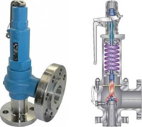
The images below show a standard Relief valve and a standard Safety valve from a well-known UK manufacturer. Each manufacturer does things slightly differently however all of the basic components and principles of operation are the same. As described previously, a safety valve differs from a relief valve in that it opens rapidly once the set pressure has been reached. For the same inlet size and with the valve in the closed position, the surface area that the pressure on the inlet side will see is the same. When the set pressure is reached and the valve starts to open, the disk on a Safety valve is larger (see the diagrams below) and hence the same pressure then sees a much larger surface area and consequently the force increases greatly causing the valve to open quickly and hence the characteristic pop action.
The image below shows the above Safety valves and Relief valves dismantled. The disk diameter on the 1" (DN25) Safety valve is only 7mm larger than on the Relief valve which doesnt sound like much, but when you calculate the areas it is an increase of 36%.
This diagram represents a Safety valve in its very simplest form. The force acting on the inlet side of the disk is acting against the force applied by the spring plus the force applied by the back pressure on the top of the disk.
The valve remains closed when(PI x Ab) < Fs + (PB x At), is in equilibrium when(PI x Ab) = Fs + (PB x At) and opens when(PI x Ab) > Fs + (PB x At) were PI = Inlet pressure, PB = Back pressure, At = Top of disk area, Ab = Bottom of disk area. Things to notice from this design are that if PB is variable and quite large relative to PI, then this will cause the pressure at which the valve opens to vary which is undesirable. The following two designs (Fig 3 & Fig 4) are available that eliminate the effect of back pressure on the set pressure.
The bellows prevents backpressure acting on the top side of the disk. In relation to the piston there is no top side within the main body of the valve hence again the back pressure cannot affect the set pressure. Bellows failure is an important concern in critical applications where a very precise set pressure is required. In these cases some mechanism to detect a leak of process medium out of the top vent would be implemented. Piston designs are not usually found in conventional Safety valves but are more common in Pilot Operated Safety valves.
API 520 Practice Guidelines: a conventional design should not typically be used when the built-up backpressure is greater than 10% of the set pressure at 10% over pressure. European standard EN ISO 4126: the built-up backpressure should be limited to 10% of the set pressure when the valve is discharging at the certified capacity.
In a conventional design (no bellows), the superimposed backpressure will affect the opening characteristic and set value, but the combined backpressure will alter the closing (blowdown) and re-seat value.
Overpressure is the percentage over the set pressure by which the valve is fully open. The blowdown is the percentage below the set pressure by which the valve is fully closed.
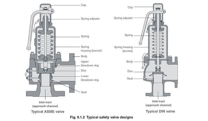
The basic elements of the design are right angle pattern valve body, inlet can be either a full nozzle or a semi-nozzle type. With a full nozzle design has the “wetted” inlet tract formed from one piece (as per figure 6) with the seat integrated into the top of the nozzle. The internal bore of the nozzle and the disc is the only part of the valve that is exposed to the process fluid with the valve in the closed position. A semi-nozzle design consists of a seating ring fitted into the body.The disc is held onto the seat by the stem, with the downward force coming from the compression on the spring mounted in the bonnet. The amount of compression on the spring is adjusted by the spring adjuster under the cap.
Unless bellows or diaphragm sealing is used, process fluid will enter the spring housing (or bonnet). The amount of fluid depends on the particular design of safety valve. If emission of this fluid into the atmosphere is acceptable, the spring housing may be vented to the atmosphere - an open bonnet. This is usually advantageous when the safety valve is used on high temperature fluids or for boiler applications as, otherwise, high temperatures can relax the spring, altering the set pressure of the valve. However, using an open bonnet exposes the valve spring and internals to environmental conditions, which can lead to damage and corrosion of the spring.
When the fluid must be completely contained by the safety valve (and the discharge system), it is necessary to use a closed bonnet, which is not vented to the atmosphere. This type of spring enclosure is almost universally used for small screwed valves and, it is becoming increasingly common on many valve ranges since, particularly on steam, discharge of the fluid could be hazardous to personnel.
A lifting mechanism is recommended to test for correct valve operation at all times where corrosion, caking, or any deposit could prevent the opening operation.
Foreign particles can lodge under the seat of the valve when it discharges. The lifting lever allows you to lift the valve and flush the obstruction. Pressure relief valves for Section VIII require a lift lever on all air, steam, and hot water valves used at temperatures over 60 degC. Typically used where periodic testing of the valve in location is desired to assure its operation. With an Open lifting lever design, when the valve discharges, fluid media will escape into the atmosphere around the open lifting lever assembly. If this is not desirable or when back pressure is present you would select a Packed Lifting Lever design.
As described above, this type is selected where leakage of the media to the atmosphere during valve discharge or during back pressure would be un-desirable. A packed lever design is a completely sealed assembly.
Some people consider a bolted and gasketed design better to the standard screw cap for applications with back pressure and / or vibration hence some manufacturers offer this as an option.
Under certain circumstances i.e. under the start-up conditions of a plant or to pressure test the system in a controlled environment, it may be required that the valve is prevented from opening.This is achieved by screwing the bolt (shown on the wire) into the cap which screws down onto the stem and prevents it lifting. Obviously it is important that test gags are removed prior to placing the valve into service.
The bellows is designed to cover the same area on the back of the disc equal to the seat area hence the back pressure will have no effect on the set pressure. See the previous section “Basic Safety Valve Principles”. Bellows also protects the spindle, spindle guide and spring from the process medium.
A disc is held against the nozzle by a spring, which is contained in a cast bonnet. The spring is adjusted by a compression screw to permit the calibration of opening or set pressure. An adjustable nozzle ring, threaded onto the nozzle, controls the geometry of the fluid exit control chamber (also known as a huddling chamber). The control chamber (huddling chamber) geometry is very important in controlling valve opening and closing pressures and stability of operation. The nozzle ring is locked into position by a ring pin assembly as shown in Figure 15 below.
Under normal system operation the valve remains in the closed position because the spring force (Fs) is greater than the system pressure acting on the internal nozzle seating area (PA). If system pressure increases to a point when these forces are equal, then the set pressure is reached. The disc lifts and fluid flows through the valve. When pressure in the system returns to a safe level, the valve closes.
Just prior to reaching set point, the pressure relief valve leaks system fluid into the huddling chamber. The fluid now acts on a larger area of the disc inside the huddling chamber (PAh), causing the valve to experience an instantaneous increase in the opening force. Refer to the figure 16 above to see relationship between Nozzle Area (A) and the Huddling Chamber Area (Ah). System pressure acting on the larger area will suddenly open the safety relief valve at a rapid rate.
Although the opening is rapid and dramatic, the valve does not open fully at set point. The system pressure must increase above set point to open the valve to its full lift and capacity position. Maximum lift and certified flow rates will be achieved within the allowable limits (overpressure) established by various codes and standards. All pressure relief ales are allowed an overpressure allowance to reach full rated flow. The allowable over pressure can vary from 10% to 21% on unfired vessels and systems, depending on the sizing basis, number of valves, and whether a fire condition is encountered.
Once the valve has controlled the pressure excursion, system pressure will start to reduce. Since the huddling chamber area is now controlling the exit fluid flow, system pressure must reduce below the set point before the spring force is able to close the valve. The difference between the set pressure and the closing pressure is called blowdown, and is usually expressed as a percentage of set pressure. The typical blowdown can vary from 7% to 10%, the industry standard.
The nozzle ring adjustment changes the shape and volume of the huddling chamber, and its position will affect both the opening and the closing characteristics of the valve. When the nozzle ring is adjusted to its top position, the huddling chamber is restricted to its maximum. The valve will usually pop very distinctly with a minimum simmer (leakage before opening), but the blowdown will increase. When the nozzle ring is lowered to its lowest position, minimal restriction to the huddling chamber occurs. At this position, simmer increases and the blowdown decreases. The final ring position is somewhere between these two extremes to provide optimal performance.
On liquid service, a different dynamic situation exists. Liquids do not expand when flowing across orifices, and a small amount of fluid flow across the nozzle will produces a large local pressure drop at the nozzle orifice. This local pressure drop causes the spring to reclose the valve if the fluid flow is minimal. Liquids leaking into the huddling chamber can quickly drain out by gravity and prevent fluid pressure from building up in the secondary area of the huddling chamber. Liquid relief valves are thus susceptible to a phenomenon called chatter, especially at low fluid flow rates. Chatter is the rapid opening and closing of the pressure relief valve and is always destructive.
Because of the difference in the characteristics of gases and liquids, some valve designs require a special liquid trim in order to meet ASME Code Section VIII performance criteria of full rated liquid flow at 10% overpressure. With liquids since no visible or audible pop is heard at set point, the set pressure is defined as the pressure when the first heavy flow occurs (a pencil sized steady stream of water that remains unbroken for approximately one inch).
Manufacturers usually state their recommended testing procedure and testing intervals in their Installation, Operating and Maintenance Instructions (IOM). Typically, they recommend a manual test every 3 or 6 months (assuming it has a lifting lever) and a set pressure test every 12 months. It is sensible to incorporate these into your maintenance plan so they are not missed. Sometimes your insurance company may require them to be tested even more regularly than this i.e. every 6 months. Testing in most cases involves removing them from your system and having them recertified in an approved workshop.
If you have a system that is shut down for annual maintenance then this is an ideal time to remove your Safety valves and have them inspected and recertified.
For systems that can only be off for short periods of time, it is sensible to keep a spare valve to swap over and then the removed valve can be inspected and recertified.
For systems that cannot be shut down, you will need to use a changeover valve which allows you to swap between Safety valves allowing one to be removed for inspection and testing.
For larger Safety valves on systems that run continuously, you may consider using in-situ testing. This method does have some limitations however since you cannot visually inspect the inside of the valve, but it will tell you if the valve is opening at the correct set pressure.
(a) A valve passing (leaking) on the outlet side when the valve is supposed to be closed. This can happen to valves of any age (new or old) and occurs if debris contained in the medium passes through the valve at a point when the valve lifts, and the debris either traps or damages the internals of the valve. On soft seated valves, hard particles may embed themselves in the soft material causing re-sealing issues. If your valve has a lifting lever and it is safe to do so, then it is worth lifting the handle for a few seconds which will hopefully clear any debris allowing the valve to reseal correctly. If this isn’t an option or it doesn’t cure the problem, then the valve will need to be removed and returned for maintenance and recertification. The time we often see this the most is during the startup of a system and there is a pressure spike, hence this is why it is extremely important that a system is flushed out well before hand.

Both pressure relief valves and pressure control valves have their own unique uses within fluid control and gas control applications. Pressure control valves and pressure relief valves have unique attributes that make them best suited to a number of very distinct and different applications. If you’ve found yourself wondering what a pressure control valve is, and the difference between the two pressure valve types, read on to learn more. Here, the fluid handling experts at Fluid Controls explain the difference between the two components; explaining the features, safety information and benefits of each valve type.
A pressure relief valve is a type of safety valve that is used in a process control system to limit or control the pressure in a system. This prevents pressure from building up, which could cause a devastating process breakdown, including equipment failure.
This means that pressure relief valves are designed to be set at a specific pressure to protect the equipment from reaching a pressure that could damage expensive equipment.
Pressure Relief Valves (PRV) were first used on steam boilers during the industrial revolution. Early boilers without them were prone to accidental Explosion due to their lack of safety features.
A pressure relief valve is a static device that can reduce pressure even if there is no flow coming out of the reservoir. They are designed to open proportionally to increasing pressure and therefore are not recommended for applications requiring immediate full valve flow at a set pressure.
The full flow of the relief valve is defined at 10% over set pressure and the two general types of protection encountered in industry are thermal protection and flow protection. These precision valves are designed for pressure gas systems, cryogenic systems, petrochemical applications and other special systems. The pressure relief valve features are designed to EN ISO 4126-1 standard, they have a lower whole lifetime cost and they optimise outlet flow for faster relieving. These valves usually release in to the drain or environment meaning that the steam or fluid that goes into the pressure release valve is naturally lost to the system.
Similar to a pressure relief valve, a pressure control valve can protect a system from the damages which is caused by excessive pressure. These valves are often found in hydraulic systems and are used to protect the hydraulic system.
Hydraulic systems employ pressure control valves in order to limit the level of maximum pressure which can protect the pump or system from overpressure.
A Pressure Control Valve (PCV) on the other hand, acts to change resistance to the flow of the fluid, but does not alter its destination. Fluid that passes through the Pressure Control Valve is still going to the destination it was proposed for and is not lost.
These valves are found in virtually every hydraulic system, and they assist in a variety of functions, from keeping system pressures safely below a desired upper limit to maintaining a set pressure in part of a circuit.
The pressure control valve features guarantee the performance of the system and optimisation of energy usage. Exact and precise control of differential pressures eliminates overflows at partial conditions and controls the temperature at low load conditions.
Here at Fluid Controls, we are proud to be able to offer a range of control valves from some of the leading names in process and fluid controls, including Burkert and Welker.
The main difference between PRV and PCV is that the PCV is called a first-line defence which is meant for primary safety. The PRV is not used as a pressure control device but as a backup of last resort. Pressure Control Valves are ideal for applications requiring a reduced pressure to a cylinder whereas Pressure Relief Valves are used to maintain a preset downstream pressure.
Here at Fluid Controls, we don’t just have the knowledge and expertise to explain what a pressure control valve is, and its difference from a pressure relief valve. We can also support you in making the correct choice of pressure control valve and pressure relief valve for your application. For more information about any of our products at Fluid Controls call us today on 0118 970 2060


 8613371530291