
how does a gas safety valve work brands

Most modern appliances have safety features built in, but your gas oven safety valve is arguably the most important. If an electrical appliance malfunctions, it can cause a fire, but a misfiring gas oven could potentially blow up your house. You don"t really need to know how the safety mechanism works to use your oven, but you may find that it gives you some extra peace of mind.
Broadly speaking, there are two ways a built-in safety mechanism can work. One option is that it remains "open" by default and to shut off if certain conditions are met. That"s how fuses and circuit breakers work in an electrical circuit: Ordinarily, the electricity is free to flow, but if the current grows too large, the fuse or breaker will blow and cut off the circulation of electricity.
The other option is for your safety mechanism to be "closed" by default and allow a device to operate only when the correct conditions are met. That"s how a gas oven safety valve works. Gas ordinarily is prevented from flowing, and if the valve is working correctly, it opens only when you want to light your oven.
Many gas stoves use what"s called a "hot surface igniter," a bar or element (similar to the ones on your stovetop) that gets hot enough to ignite the gas on contact. Gas oven safety valves on stoves with this type of ignition system take a couple of different approaches.
In one approach, a bimetallic strip operates the valve. It harnesses a simple scientific principle: Metals expand and contract at different rates when they"re heated and cooled. If you bond two suitable metals together in one strip, that strip will flex to a predictable degree as the temperature goes up and down. Wall-mount thermostats often use this principle, as do analog oven thermometers and the thermometer in the lid of your gas grill.
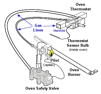
As appliance-repair website PartSelect explains, turning on your gas oven causes electricity to flow into the heating element of your hot surface igniter. As the igniter heats up, it warms a bimetallic strip inside your gas oven safety valve. When the igniter reaches its operating temperature, the bimetallic strip opens the valve and allows the gas to flow, igniting as it crosses the heated surface.
One intriguing thing about electricity is that a change in temperature can affect how well it passes through certain materials. For example, a lot of research revolves around superconductors – materials that offer very little resistance to an electrical current – but superconductors typically must be heavily chilled to work.
According to heating-equipment vendor Anglo Nordic, gas oven safety valves use a variation of that principle to operate. In these stoves, the flow of electrical current through the hot surface igniter becomes the control mechanism. The igniter"s bar is made of a material that offers less and less resistance to electricity as it heats. When it reaches the temperature required to ignite the gas, its resistance becomes low enough to trip the safety valve and open the flow of gas.
More modern ranges use an electrical igniter. When you turn on your oven, the gas begins flowing immediately, and it sends an electrical current to a piezo electric igniter. The current makes the igniter spark (like the manual igniter on your gas grill) and lights the oven"s burner. In this case, the safety valve works in the opposite way: An electronic sensor checks for the heat caused by ignition after a few seconds, and if it"s absent, it will close the valve and shut off the flow of gas.
It"s worth pointing out that not all gas ovens have a safety valve in the conventional sense. Older stoves simply use a pilot light, a small but constant flow of gas, which, in turn, feeds a small, candle-like flame. You essentially are the safety mechanism in this system: It"s up to you to check that the pilot is lit. When you turn on the gas manually, the small pilot flame ignites the main flame. It"s a mechanically simple system, which makes it durable, and for that reason, you"ll still see it used on commercial restaurant ranges, which must stand up to decades of heavy use.
First developed for use on early steam boilers as operating without them would cause an explosion unless carefully operated. Modern burner ovens now feature a gas safety valve to prevent an explosion when unlit. Unless ignited by an electric glow bar, pilot flame or electric spark with a gas supply, the valve will remain closed.
Safety should be you’re top priority when you’re working with gas. If you’re not careful, its extremely easy to cause a lot of damage. To prevent this modern day gas safety valves have been fitted around the world, to ensure an efficiently working system.
When your gas safety valves are on their last legs, making a repair or finding a replacement is the best thing to do. Keeping a spare in your kit is highly recommended.
The glow bar igniter and safety valve are wired in series within a glow bar system. This means that electricity can only pass through the valve after it has first passed through the glow bar. Electrical resistance from the glow bar blocks current to the gas valve, making sure that the valve closes. This decreases as the temperature increases. When the bar reaches a particular heat, enough to ignite the gas, it allows sufficient electricity through to open the gas valve.
The gas ignition source on Pilot light ignition system uses a low flame, fed by a line from the thermostat. The pilot flame will either burn constantly or be ignited electronically when the oven is switched on. More gas is fed to the pilot flame when the oven thermostat wants heat. Either excess pressure or an electric current will open the gas valve.
With some ovens the burner is directly ignited with an electric spark. An electric spark is sent to ignite the burner when the gas valve opens, this is due to the thermostat wanting heat. A sensor on the burner detects the flame and confirms ignition. The oven burner will lock out if there is no ignition after two attempts.
Pressure relief valves are usually installed in multi appliance, oil pumped ringmain systems. They are used to maintain a constant pressure on the positive side of the pump whether all appliances are in use or not.
Safety relief discharge pressurised gases and vapours to protect against overpressure. This is done by discharging pressurised gases and vapours from pipelines, this includes pressure vessels and plant components. Safety relief valves are the last line of defence and prevent explosion which could be fatal.
These spring-loaded and direct-acting. When the opening pressure is reached, valve gives way and opens, releasing the pressure. The pressures then equalised and the automatically closes.
Relief valves can either discharge into atmosphere, or via a connected blow-off line. The opening pressure of the boiler relief valve valve is preset usually at the factory according to the customer’s requirements.
Anglo Nordic have just what you need! If you have any questions for need more information, simply call us on 0208 979 0988 or email us at sales@anglo-nordic.com
There is a wide range of safety valves available to meet the many different applications and performance criteria demanded by different industries. Furthermore, national standards define many varying types of safety valve.
The ASME standard I and ASME standard VIII for boiler and pressure vessel applications and the ASME/ANSI PTC 25.3 standard for safety valves and relief valves provide the following definition. These standards set performance characteristics as well as defining the different types of safety valves that are used:
ASME I valve - A safety relief valve conforming to the requirements of Section I of the ASME pressure vessel code for boiler applications which will open within 3% overpressure and close within 4%. It will usually feature two blowdown rings, and is identified by a National Board ‘V’ stamp.
ASME VIII valve- A safety relief valve conforming to the requirements of Section VIII of the ASME pressure vessel code for pressure vessel applications which will open within 10% overpressure and close within 7%. Identified by a National Board ‘UV’ stamp.
Full bore safety valve - A safety valve having no protrusions in the bore, and wherein the valve lifts to an extent sufficient for the minimum area at any section, at or below the seat, to become the controlling orifice.
Conventional safety relief valve -The spring housing is vented to the discharge side, hence operational characteristics are directly affected by changes in the backpressure to the valve.
Balanced safety relief valve -A balanced valve incorporates a means of minimising the effect of backpressure on the operational characteristics of the valve.
Pilot operated pressure relief valve -The major relieving device is combined with, and is controlled by, a self-actuated auxiliary pressure relief device.
Power-actuated safety relief valve - A pressure relief valve in which the major pressure relieving device is combined with, and controlled by, a device requiring an external source of energy.
Standard safety valve - A valve which, following opening, reaches the degree of lift necessary for the mass flowrate to be discharged within a pressure rise of not more than 10%. (The valve is characterised by a pop type action and is sometimes known as high lift).
Full lift (Vollhub) safety valve -A safety valve which, after commencement of lift, opens rapidly within a 5% pressure rise up to the full lift as limited by the design. The amount of lift up to the rapid opening (proportional range) shall not be more than 20%.
Direct loaded safety valve -A safety valve in which the opening force underneath the valve disc is opposed by a closing force such as a spring or a weight.
Proportional safety valve - A safety valve which opens more or less steadily in relation to the increase in pressure. Sudden opening within a 10% lift range will not occur without pressure increase. Following opening within a pressure of not more than 10%, these safety valves achieve the lift necessary for the mass flow to be discharged.
Diaphragm safety valve -A direct loaded safety valve wherein linear moving and rotating elements and springs are protected against the effects of the fluid by a diaphragm
Bellows safety valve - A direct loaded safety valve wherein sliding and (partially or fully) rotating elements and springs are protected against the effects of the fluids by a bellows. The bellows may be of such a design that it compensates for influences of backpressure.
Controlled safety valve - Consists of a main valve and a control device. It also includes direct acting safety valves with supplementary loading in which, until the set pressure is reached, an additional force increases the closing force.
Safety valve - A safety valve which automatically, without the assistance of any energy other than that of the fluid concerned, discharges a quantity of the fluid so as to prevent a predetermined safe pressure being exceeded, and which is designed to re-close and prevent further flow of fluid after normal pressure conditions of service have been restored. Note; the valve can be characterised either by pop action (rapid opening) or by opening in proportion (not necessarily linear) to the increase in pressure over the set pressure.
Direct loaded safety valve -A safety valve in which the loading due to the fluid pressure underneath the valve disc is opposed only by a direct mechanical loading device such as a weight, lever and weight, or a spring.
Assisted safety valve -A safety valve which by means of a powered assistance mechanism, may additionally be lifted at a pressure lower than the set pressure and will, even in the event of a failure of the assistance mechanism, comply with all the requirements for safety valves given in the standard.
Supplementary loaded safety valve - A safety valve that has, until the pressure at the inlet to the safety valve reaches the set pressure, an additional force, which increases the sealing force.
Note; this additional force (supplementary load), which may be provided by means of an extraneous power source, is reliably released when the pressure at the inlet of the safety valve reaches the set pressure. The amount of supplementary loading is so arranged that if such supplementary loading is not released, the safety valve will attain its certified discharge capacity at a pressure not greater than 1.1 times the maximum allowable pressure of the equipment to be protected.
Pilot operated safety valve -A safety valve, the operation of which is initiated and controlled by the fluid discharged from a pilot valve, which is itself, a direct loaded safety valve subject to the requirement of the standard.
The common characteristic shared between the definitions of conventional safety valves in the different standards, is that their operational characteristics are affected by any backpressure in the discharge system. It is important to note that the total backpressure is generated from two components; superimposed backpressure and the built-up backpressure:
Subsequently, in a conventional safety valve, only the superimposed backpressure will affect the opening characteristic and set value, but the combined backpressure will alter the blowdown characteristic and re-seat value.
The ASME/ANSI standard makes the further classification that conventional valves have a spring housing that is vented to the discharge side of the valve. If the spring housing is vented to the atmosphere, any superimposed backpressure will still affect the operational characteristics. Thiscan be seen from Figure 9.2.1, which shows schematic diagrams of valves whose spring housings are vented to the discharge side of the valve and to the atmosphere.
By considering the forces acting on the disc (with area AD), it can be seen that the required opening force (equivalent to the product of inlet pressure (PV) and the nozzle area (AN)) is the sum of the spring force (FS) and the force due to the backpressure (PB) acting on the top and bottom of the disc. In the case of a spring housing vented to the discharge side of the valve (an ASME conventional safety relief valve, see Figure 9.2.1 (a)), the required opening force is:
In both cases, if a significant superimposed backpressure exists, its effects on the set pressure need to be considered when designing a safety valve system.
Once the valve starts to open, the effects of built-up backpressure also have to be taken into account. For a conventional safety valve with the spring housing vented to the discharge side of the valve, see Figure 9.2.1 (a), the effect of built-up backpressure can be determined by considering Equation 9.2.1 and by noting that once the valve starts to open, the inlet pressure is the sum of the set pressure, PS, and the overpressure, PO.
Balanced safety valves are those that incorporate a means of eliminating the effects of backpressure. There are two basic designs that can be used to achieve this:
Although there are several variations of the piston valve, they generally consist of a piston type disc whose movement is constrained by a vented guide. The area of the top face of the piston, AP, and the nozzle seat area, AN, are designed to be equal. This means that the effective area of both the top and bottom surfaces of the disc exposed to the backpressure are equal, and therefore any additional forces are balanced. In addition, the spring bonnet is vented such that the top face of the piston is subjected to atmospheric pressure, as shown in Figure 9.2.2.
The bellows arrangement prevents backpressure acting on the upper side of the disc within the area of the bellows. The disc area extending beyond the bellows and the opposing disc area are equal, and so the forces acting on the disc are balanced, and the backpressure has little effect on the valve opening pressure.
Bellows failure is an important concern when using a bellows balanced safety valve, as this may affect the set pressure and capacity of the valve. It is important, therefore, that there is some mechanism for detecting any uncharacteristic fluid flow through the bellows vents. In addition, some bellows balanced safety valves include an auxiliary piston that is used to overcome the effects of backpressure in the case of bellows failure. This type of safety valve is usually only used on critical applications in the oil and petrochemical industries.
In addition to reducing the effects of backpressure, the bellows also serve to isolate the spindle guide and the spring from the process fluid, this is important when the fluid is corrosive.
Since balanced pressure relief valves are typically more expensive than their unbalanced counterparts, they are commonly only used where high pressure manifolds are unavoidable, or in critical applications where a very precise set pressure or blowdown is required.
This type of safety valve uses the flowing medium itself, through a pilot valve, to apply the closing force on the safety valve disc. The pilot valve is itself a small safety valve.
The diaphragm type is typically only available for low pressure applications and it produces a proportional type action, characteristic of relief valves used in liquid systems. They are therefore of little use in steam systems, consequently, they will not be considered in this text.
The piston type valve consists of a main valve, which uses a piston shaped closing device (or obturator), and an external pilot valve. Figure 9.2.4 shows a diagram of a typical piston type, pilot operated safety valve.
The piston and seating arrangement incorporated in the main valve is designed so that the bottom area of the piston, exposed to the inlet fluid, is less than the area of the top of the piston. As both ends of the piston are exposed to the fluid at the same pressure, this means that under normal system operating conditions, the closing force, resulting from the larger top area, is greater than the inlet force. The resultant downward force therefore holds the piston firmly on its seat.
If the inlet pressure were to rise, the net closing force on the piston also increases, ensuring that a tight shut-off is continually maintained. However, when the inlet pressure reaches the set pressure, the pilot valve will pop open to release the fluid pressure above the piston. With much less fluid pressure acting on the upper surface of the piston, the inlet pressure generates a net upwards force and the piston will leave its seat. This causes the main valve to pop open, allowing the process fluid to be discharged.
When the inlet pressure has been sufficiently reduced, the pilot valve will reclose, preventing the further release of fluid from the top of the piston, thereby re-establishing the net downward force, and causing the piston to reseat.
Pilot operated safety valves offer good overpressure and blowdown performance (a blowdown of 2% is attainable). For this reason, they are used where a narrow margin is required between the set pressure and the system operating pressure. Pilot operated valves are also available in much larger sizes, making them the preferred type of safety valve for larger capacities.
One of the main concerns with pilot operated safety valves is that the small bore, pilot connecting pipes are susceptible to blockage by foreign matter, or due to the collection of condensate in these pipes. This can lead to the failure of the valve, either in the open or closed position, depending on where the blockage occurs.
The terms full lift, high lift and low lift refer to the amount of travel the disc undergoes as it moves from its closed position to the position required to produce the certified discharge capacity, and how this affects the discharge capacity of the valve.
A full lift safety valve is one in which the disc lifts sufficiently, so that the curtain area no longer influences the discharge area. The discharge area, and therefore the capacity of the valve are subsequently determined by the bore area. This occurs when the disc lifts a distance of at least a quarter of the bore diameter. A full lift conventional safety valve is often the best choice for general steam applications.
The disc of a high lift safety valve lifts a distance of at least 1/12th of the bore diameter. This means that the curtain area, and ultimately the position of the disc, determines the discharge area. The discharge capacities of high lift valves tend to be significantly lower than those of full lift valves, and for a given discharge capacity, it is usually possible to select a full lift valve that has a nominal size several times smaller than a corresponding high lift valve, which usually incurs cost advantages.Furthermore, high lift valves tend to be used on compressible fluids where their action is more proportional.
In low lift valves, the disc only lifts a distance of 1/24th of the bore diameter. The discharge area is determined entirely by the position of the disc, and since the disc only lifts a small amount, the capacities tend to be much lower than those of full or high lift valves.
Except when safety valves are discharging, the only parts that are wetted by the process fluid are the inlet tract (nozzle) and the disc. Since safety valves operate infrequently under normal conditions, all other components can be manufactured from standard materials for most applications. There are however several exceptions, in which case, special materials have to be used, these include:
Cast steel -Commonly used on higher pressure valves (up to 40 bar g). Process type valves are usually made from a cast steel body with an austenitic full nozzle type construction.
For all safety valves, it is important that moving parts, particularly the spindle and guides are made from materials that will not easily degrade or corrode. As seats and discs are constantly in contact with the process fluid, they must be able to resist the effects of erosion and corrosion.
For process applications, austenitic stainless steel is commonly used for seats and discs; sometimes they are ‘stellite faced’ for increased durability. For extremely corrosive fluids, nozzles, discs and seats are made from special alloys such as ‘monel’ or ‘hastelloy’.
The spring is a critical element of the safety valve and must provide reliable performance within the required parameters. Standard safety valves will typically use carbon steel for moderate temperatures. Tungsten steel is used for higher temperature, non-corrosive applications, and stainless steel is used for corrosive or clean steam duty. For sour gas and high temperature applications, often special materials such as monel, hastelloy and ‘inconel’ are used.
A key option is the type of seating material used. Metal-to-metal seats, commonly made from stainless steel, are normally used for high temperature applications such as steam. Alternatively, resilient discs can be fixed to either or both of the seating surfaces where tighter shut-off is required, typically for gas or liquid applications. These inserts can be made from a number of different materials, but Viton, nitrile or EPDM are the most common. Soft seal inserts are not generally recommended for steam use.
Standard safety valves are generally fitted with an easing lever, which enables the valve to be lifted manually in order to ensure that it is operational at pressures in excess of 75% of set pressure. This is usually done as part of routine safety checks, or during maintenance to prevent seizing. The fitting of a lever is usually a requirement of national standards and insurance companies for steam and hot water applications. For example, the ASME Boiler and Pressure Vessel Code states that pressure relief valves must be fitted with a lever if they are to be used on air, water over 60°C, and steam.
A standard or open lever is the simplest type of lever available. It is typically used on applications where a small amount of leakage of the fluid to the atmosphere is acceptable, such as on steam and air systems, (see Figure 9.2.5 (a)).
Where it is not acceptable for the media to escape, a packed lever must be used. This uses a packed gland seal to ensure that the fluid is contained within the cap, (see Figure 9.2.5 (b)).
For service where a lever is not required, a cap can be used to simply protect the adjustment screw. If used in conjunction with a gasket, it can be used to prevent emissions to the atmosphere, (see Figure 9.2.6).
A test gag (Figure 9.2.7) may be used to prevent the valve from opening at the set pressure during hydraulic testing when commissioning a system. Once tested, the gag screw is removed and replaced with a short blanking plug before the valve is placed in service.
The amount of fluid depends on the particular design of safety valve. If emission of this fluid into the atmosphere is acceptable, the spring housing may be vented to the atmosphere – an open bonnet. This is usually advantageous when the safety valve is used on high temperature fluids or for boiler applications as, otherwise, high temperatures can relax the spring, altering the set pressure of the valve. However, using an open bonnet exposes the valve spring and internals to environmental conditions, which can lead to damage and corrosion of the spring.
When the fluid must be completely contained by the safety valve (and the discharge system), it is necessary to use a closed bonnet, which is not vented to the atmosphere. This type of spring enclosure is almost universally used for small screwed valves and, it is becoming increasingly common on many valve ranges since, particularly on steam, discharge of the fluid could be hazardous to personnel.
Some safety valves, most commonly those used for water applications, incorporate a flexible diaphragm or bellows to isolate the safety valve spring and upper chamber from the process fluid, (see Figure 9.2.9).
An elastomer bellows or diaphragm is commonly used in hot water or heating applications, whereas a stainless steel one would be used on process applications employing hazardous fluids.

Safety valves. It took me a little while to figure out how they worked, what their true purpose was. But let’s start with the outside of the stove. There’s a “CP” logo. That stands for “Certified Product” and is a trademark by the American Stove Makers Association that ensures that your stove meets certain high standards, like the stove’s oven/broiler safety systems. A highly respected and knowledgeable vintage stove sage I know (Steve S.) said about 20 criteria must be met to earn the designation.My OKM vintage gas stove has safety valves and connected thermocouples for a safer operation of the oven and broiler.
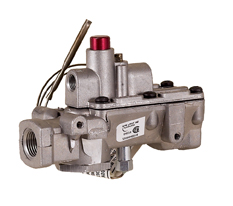
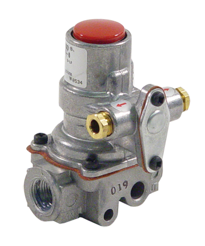
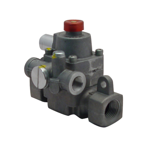
The Robertshaw TS Series thermomagnetic safety valve is a control used to cut off the flow of gas to the burner in the event of a pilot outage. The magnet assembly is energized by voltage generated by a thermocouple that is heated by the pilot flame. When this flame is extinguished, the thermocouple voltage decreases until a spring overcomes the magnetic force and loses off both the pilot and main gas (the older valves just shut off the main burner gas). This control can be used for commercial and residential ovens, infrared heaters, chicken and pig brooders, recreational vehicle gas appliances and many more applications requiring automatic safety valves!
What it means is if, for any reason, the gas flow to the stove stops while the oven or broiler burners were on, in addition to the burners going out the pilot flame would go out. That would cool down the thermocouple probe which sits in the pilot flame. When the thermocouple is not hot enough, it signals the safety valve to close, which blocks gas from flowing to the burners.
WHY?Prior to safety systems existing, when these stoves were being produced, gas distribution was not always reliable. Sometimes, the gas supply would die out, shutting off the flames. Then after a little while, the gas would come back on.
Unlike the cooktop burners, the oven burner is hidden. If say, a bread baker were only using the oven at that time the gas supply stopped then started again, she or he might not have realized what happened. It was possible the baker might open the oven to check, realize the flame had gone out and try to relight the manually lit oven with a match.
With a safety system, when the gas flow was re-established to the entire stove, the safety valve would have prevented the raw gas from filling up the oven or broiler chambers because the valve closed when the pilot light went out.
These days, gas distribution is pretty reliable. Most often safety valves can seem to be a problem for three reasons: a) after the gas has been shut off from the stove (so the stove can be safely repaired or relocated), b) when the thermocouple bimetal’s charge dwindles and dies, c) when the safety valve loses its magnetic charge and cannot stay open.
When my gas stove was moved into my kitchen, I needed to perform a manual reset of the two safety valves so I could test the oven and broiler. When the stove was disconnected from the previous owner’s gas line, that killed the pilot flames which cooled the thermocouples which closed the safety valves.
Each time I worked on my stove’s major systems, I’d shut off the gas to the stove. To restart the oven and broiler burners, I’d have to manually reset the safety valves if I wanted the oven and broiler to auto light again.
Made sure the pilot flame is on and the thermocouple probe is in that flame. The heat causes the thermocouple to charge and send a signal to the safety valve. The signal cannot open the safety valve, but it can only keep it open. If the pilot is not lit, I’d light it and wait about a minute for it to warm up enough to signal the safety valve.
Pushed in and held the red button on the safety valve. Pushing the button manually opens the safety valve, allowing the gas to flow to the oven/broiler burner. Once the gas flow reached the burner, the pilot flame would ignite the oven burner. Small happy dance.
Released the button on the safety valve. When everything worked properly, the safety valve would stay open, because the thermocouple sent a signal for it to stay open. Big happy dance. If the oven burner shut off after that process, I assumed the thermocouple signal was too weak to keep the safety valve open. Time for a new thermocouple. Pout! Or the safety was on the fritz. Major $$$ pout!
If you have a multimeter with a DC volt scale, you can use that to test your thermocouple’s charge. But don’t ask me how. I’ve no meter nor knowledge on such things.
There are many different safety valve model for major gas appliances like stoves, water heaters and furnaces, but they all have the same purpose – to prevent raw or uncombusted gas from leaking. Their designs and features have evolved over the years. If you’re trying to find a replacement safety valve for your stove, you don’t have to necessarily get original unit.
But you do need to make sure the replacement valve meets all the critical requirements. For example, the gas line openings need to be the match the diameter of the gas lines in your stove, it needs to have correct port for the thermocouple, it needs to fit the opening of the previous unit, etc. There are workarounds for most of that, but it involves plumbing adapters, additional gas lines and/or plumbers.
When my old gas furnace safety died, troubleshooting pointed to the safety valve as the trouble. I disconnected it and took it to a local appliance parts shop. Thankfully, the owner recognized my old no-longer-available furnace safety valve and knew which updated model would work.
The Robertshaw® 1720 Series Thermomagnetic Safety Valve is a control used to cut off the flow of gas to the burner in the event of a pilot outage. The magnet assembly is energized by voltage generated by a thermocouple that is heated by the pilot flame. When this flame is extinguished, the thermocouple voltage decreases until a spring overcomes the magnetic force and closes off both the pilot and main gas. This control can be used for commercial and residential ovens, infrared heaters, chicken and pig brooders, recreational vehicle gas appliances and many more applications requiring automatic safety valves.

1. The FMDA safety valve is the only type with the thermocouple permanently attached to it. This means the thermocouple cannot be replaced; the entire safety valve must be replaced if the thermocouple fails. The easiest way to identify an FMDA type safety is a ½” diameter red button on the bottom of the valve. You must know the gas pipe size and if the pilot tube is an “in and out” or an “out only.” An “in and out” safety valve has two threaded holes at the top of the part, one for gas for the pilot to come in and one for gas to go out. An “out only” safety valve has just one threaded hole to connect gas for the pilot to.
2. The BASO safety valve can vary in design depending on the piece of equipment it is on, so it is important to know the brand name, model and serial number of the piece of equipment to get the correct safety valve the first time. The easiest way to identify a BASO valve is by the 15/16” diameter red pilot button. The thermocouple is separate from the safety.
3. The TS type safety valve is the only one that can be rebuilt. It is similar to the FMDA and BASO types in that it has “in and out” or “out only” pilot tubing, so you must know what is in your equipment. A rebuilt kit is available in both and it is not necessary to replace the body unless it is damaged. The body has no moving parts in it. The easiest way to identify the TS safety is by the 5/8” diameter red button. The thermocouple is also separate from this safety, similar to the BASO.
If the wire leads are screwed to the top terminal block, and two tubes are coming out of the top of the valve, it is the tubing type combination safety valve.
Pilot-operated valves are pressure relief valves that control the main valve’s inlet and outlet port. They are similar to spring-loaded valves but are the best alternative solution for reaching the highest pressure and highest capacity. These valves offer excellent performance for overpressure protection. This valve type was initially recognized as a unique solution to withstand high backpressure or improve system stability, but its outstanding capability to optimize valve selection is often overlooked. Due to their compact design, these valves are typically used in the oil and gas industry, especially upstream in offshore applications.
Any pilot-operated valve is designed to withstand higher backpressure than a spring-loaded valve. The main valve piston is protected by the guide and balanced without having any fragile components that are prone to fail. The main valve has the same pressure at the inlet and on the dome—the dome is the upper part of the main valve, and due to sectional area variation, drawback force is applied on the piston. The pilot opens when you increase the pressure and reach the set point. It disconnects the upper part of the piston. The pressure is a direct vacuum to the atmosphere, making the piston open and relieving the main valve’s total capacity.
However, when several valves are connected to the same flare, the superimposed backpressure can exceed inlet pressure, and the upward force generated can open the main valve prematurely. It works with the main valve, which the pilot controls. As pressure is transmitted from the main valve inlet to the dome chamber through interconnecting tubing, a positive load is exerted on the main valve disc. This loading is due to the 30% larger dome seal area relative to the inlet seat.
Pilot-operated valves are the ones to go with when you have a significant pressure drop for its capacity to modulate. Many accessories can connect to a pilot valve as it is significantly easier than a spring-loaded valve. It also has a better size and pressure capability than the spring-loaded valves. The pilot-operated valves can be directly connected to your vessel using a static or remote sensing line. The pilot controls the main valve and allows it to keep its open position whatever the pressure drop at the inlet.
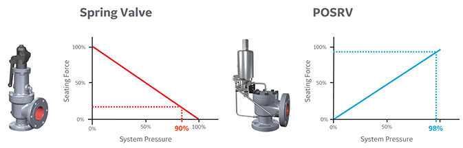
Trillium Flow Technologies manufactures a complete range of application-specific pilot-operated pressure relief valves. They are the most advanced pilot-operated valve design to provide tight shut-off at 98% set pressure. These valves ensure minimal product loss, avoid oversizing consequences, and reduce environmental pollution in any industry relief situation. We provide exceptional service and solutions to meet the changing market needs by expanding pilot-operated capabilities, making them an undisputed pressure relief solution provider for any industrial application.
Seismic shut-off valves are a simple, but effective way to ensure you never experience a gas fire after an earthquake. They are designed for earthquakes, accidents and any event of impact. We have installed thousands of automatic gas shut off valves to the manufacture’s specification to ensure safe, trouble free use.
The seismic valves work on a simple, consistent and accurate principle. A sensor moves when the valve is subjected to a 5.4 magnitude or larger earthquake, releasing the valve float which blocks the line and prevents gas going in to the building. The valve is then manually reset once a safety inspection has been done and you’re sure there are no leaks in the building.
Each valve is tested and certified before leaving the factory to meet approval from the State Board of Architect and LA Counties stringent requirements. They are tested to ASCE 25-97, State of California 12-23-1 & ANSI Z21.70-1981 Standards for Seismic Gas Valves.
Some cities and counties in California have regulations that require the installation of automatic gas shut-off devices, which may include excess flow gas shut-off valves and/or seismic gas shut-off valves. Regulations vary, but generally apply to new building construction, or significant alterations or additions to existing buildings.
If a customer installs an automatic gas shut-off valve, it should be one that is certified by the State of California and it should be installed by a licensed plumbing contractor in accordance to the manufacturers instructions.PG&Edoes not install or service seismic actuated or excess flow gas shut-off valves, or recommend specific contractors for customer applications.
Non-emergency shut-offs will occur if the automatic gas shut-off is not installed according to manufacturer’s specifications. For example, the impact of heavy vehicles can trigger a non-emergency shut-off. They operate on movement and shut off the supply of gas to a building, when triggered by a 5.4 magnitude or larger Earthquake.

Curtiss-Wright"s selection of Pressure Relief Valves comes from its outstanding product brands Farris and Target Rock. We endeavor to support the whole life cycle of a facility and continuously provide custom products and technologies. Boasting a reputation for producing high quality, durable products, our collection of Pressure Relief Valves is guaranteed to provide effective and reliable pressure relief.
While some basic components and activations in relieving pressure may differ between the specific types of relief valves, each aims to be 100% effective in keeping your equipment running safely. Our current range includes numerous valve types, from flanged to spring-loaded, threaded to wireless, pilot operated, and much more.
A pressure relief valve is a type of safety valve designed to control the pressure in a vessel. It protects the system and keeps the people operating the device safely in an overpressure event or equipment failure.
A pressure relief valve is designed to withstand a maximum allowable working pressure (MAWP). Once an overpressure event occurs in the system, the pressure relief valve detects pressure beyond its design"s specified capability. The pressure relief valve would then discharge the pressurized fluid or gas to flow from an auxiliary passage out of the system.
Below is an example of one of our pilot operated pressure relief valves in action; the cutaway demonstrates when high pressure is released from the system.
Air pressure relief valves can be applied to a variety of environments and equipment. Pressure relief valves are a safety valve used to keep equipment and the operators safe too. They"re instrumental in applications where proper pressure levels are vital for correct and safe operation. Such as oil and gas, power generation like central heating systems, and multi-phase applications in refining and chemical processing.
At Curtiss-Wright, we provide a range of different pressure relief valves based on two primary operations – spring-loaded and pilot operated. Spring-loaded valves can either be conventional spring-loaded or balanced spring-loaded.
Spring-loaded valves are programmed to open and close via a spring mechanism. They open when the pressure reaches an unacceptable level to release the material inside the vessel. It closes automatically when the pressure is released, and it returns to an average operating level. Spring-loaded safety valves rely on the closing force applied by a spring onto the main seating area. They can also be controlled in numerous ways, such as a remote, control panel, and computer program.
Pilot-operated relief valves operate by combining the primary relieving device (main valve) with self-actuated auxiliary pressure relief valves, also known as the pilot control. This pilot control dictates the opening and closing of the main valve and responds to system pressure. System pressure is fed from the inlet into and through the pilot control and ultimately into the main valve"s dome. In normal operating conditions, system pressure will prevent the main valve from opening.
The valves allow media to flow from an auxiliary passage and out of the system once absolute pressure is reached, whether it is a maximum or minimum level.
When the pressure is below the maximum amount, the pressure differential is slightly positive on the piston"s dome size, which keeps the main valve in the closed position. When system pressure rises and reaches the set point, the pilot will cut off flow to the dome, causing depressurization in the piston"s dome side. The pressure differential has reversed, and the piston will rise, opening the main valve, relieving pressure.
When the process pressure decreases to a specific pressure, the pilot closes, the dome is repressurized, and the main valve closes. The main difference between spring-loaded PRVs and pilot-operated is that a pilot-operated safety valve uses pressure to keep the valve closed.
Pilot-operated relief valves are controlled by hand and are typically opened often through a wheel or similar component. The user opens the valve when the gauge signifies that the system pressure is at an unsafe level; once the valve has opened and the pressure has been released, the operator can shut it by hand again.
Increasing pressure helps to maintain the pilot"s seal. Once the setpoint has been reached, the valve opens. This reduces leakage and fugitive emissions.
At set pressure the valve snaps to full lift. This can be quite violent on large pipes with significant pressure. The pressure has to drop below the set pressure in order for the piston to reseat.
The pilot is designed to open gradually, so that less of the system fluid is lost during each relief event. The piston lifts in proportion to the overpressure.
At Curtiss-Wright we also provide solutions for pressure relief valve monitoring. Historically, pressure relief valves have been difficult or impossible to monitor. Our SmartPRV features a 2600 Series pressure relief valve accessorized with a wireless position monitor that alerts plant operators during an overpressure event, including the time and duration.
There are many causes of overpressure, but the most common ones are typically blocked discharge in the system, gas blowby, and fire. Even proper inspection and maintenance will not eliminate the occurrence of leakages. An air pressure relief valve is the only way to ensure a safe environment for the device, its surroundings, and operators.
A PRV and PSV are interchangeable, but there is a difference between the two valves. A pressure release valve gradually opens when experiencing pressure, whereas a pressure safety valve opens suddenly when the pressure hits a certain level of over pressurization. Safety valves can be used manually and are typically used for a permanent shutdown. Air pressure relief valves are used for operational requirements, and they gently release the pressure before it hits the maximum high-pressure point and circulates it back into the system.
Pressure relief valves should be subject to an annual test, one per year. The operator is responsible for carrying out the test, which should be done using an air compressor. It’s imperative to ensure pressure relief valves maintain their effectiveness over time and are checked for signs of corrosion and loss of functionality. Air pressure relief valves should also be checked before their installation, after each fire event, and regularly as decided by the operators.
Direct-acting solenoid valves have a direct connection with the opening and closing armature, whereas pilot-operated valves use of the process fluid to assist in piloting the operation of the valve.
A control valve works by varying the rate of fluid passing through the valve itself. As the valve stem moves, it alters the size of the passage and increases, decreases or holds steady the flow. The opening and closing of the valve is altered whenever the controlled process parameter does not reach the set point.
Control valves are usually at floor level or easily accessible via platforms. They are also located on the same equipment or pipeline as the measurement and downstream or flow measurements.
An industrial relief valve is designed to control or limit surges of pressure in a system, most often in fluid or compressed air system valves. It does so as a form of protection for the system and defending against instrument or equipment failure. They are usually present in clean water industries.
A PRV is often referred to as a pressure relief valve, which is also known as a PSV or pressure safety valve. They are used interchangeably throughout the industry depending on company standards.
If you have been searching for a safety release valve that you can use to reduce short-term pressure surges successfully and diminish the effects of gas leaks, this is the product for ...
... regulators have safety valves which will slam shut in the event of emergencies, such as the gas reaching too high a pressure level. The valve works to protect any fittings ...
This product has hydraulically actuated class A gas safety valves to EN 161 used for automatic shut-off. It shuts off when unstimulated for gas and air, ...
The S 104 Safety Shut Off valve is mainly used to avoid any damage to components as well as to avoid too high or too low pressure in the gas train. This could cause high financial losses ...
The S50 Safety Shut Off valve is mainly used to avoid any damage to components as well as to avoid too high or too low pressure in the gas train. This could cause high financial losses ...
The S100 Safety Shut Off valve is mainly used to avoid any damage to components as well as to avoid too high or too low pressure in the gas train. This could cause high financial losses ...
... Pressure Safety Valve + Rupture Disk is protected and may be utilized autonomously as essential security gadgets or in conjunction. There are 3 possible combinations. The first combinations ...
It"s a Safety valve in according with Directives ATEX 20K/34/EU. Technical Norm Fire Prevention 41/256 31/10/2019. d.P.R. 10/520 19/03/1955 and subsequent amendments.
This range of spring loaded conventional and balanced safety relief valves is specifically designed for overpressure protection of unfired pressure vessel (ASME Section VIII application). ...
130 Series Safety valves are also available as Relief valves. Relief valves, identified by the letter R after the type number, are devices with an operational function, ...
V651 Series safety relief valves are produced as safety and relief type. Safety valves are pressure relief elements used to evacuate excessive pressure ...
PVS type slam shut valves are pilot-operated relief valves in which the opening and the closing of the main plug is controlled by a pilot device which is very ...
The EMERSON BM7 SERIES is a disk slam-shut valve characterized as automatic isolating elements, which are suitable for installation as safety devices in regulating stations. This device has a high operation ...
... control and regulate the gas, air flow to burners and other combustion devices. HMV is a unique safety valve that can be supplied for the requiremen of handling higher ...
Type 50 is a safety valve for universal use. It can be used for nearly any industrial application, e.g. in shipping and pipeline construction, the chemical and petrochemical industries, ...
The RIEGER Safety valve Type SH prevents excessive pressure in steam and gaseous media in plant components and tanks. The set pressure is generally higher than the operating pressure of the system.
... sewage, gas, glycol, diathermic oil, industrial water, steam and other natural and aggressive media, depending on theresistance of materials usedfor the construction ofthe valve.
With DirectIndustry you can: Find the product, subcontractor or service provider you need | Find a nearby distributor or reseller| Contact the manufacturer to get a quote or a price | Examine product characteristics and technical specifications for major brands | View PDF catalogues and other online documentation

Robertshaw® has been creating and implementing innovative solutions throughout its history. Robertshaw continues to develop ground-breaking solutions that make products more effective, more efficient, and more attainable.

Safety valves play an important role in keeping people and equipment safe. Building on the long legacy of the Consolidated Safety Valves, we work closely with customers and regulatory organizations to configure, engineer, and manufacture safety valves that can help maintain safer operating conditions in a full range of environments.
Our safety valves comply with the ASME Section I code for boiler applications. They are built with many features that meet ASME requirements for steam-compressible fluids. Baker Hughes’s Consolidated safety valves are known for exceptional quality, performance and dependability. It is important they are reliable even the in most demanding real-world applications. With a range of styles, models, options and configurations, our safety valves work in many different applications.
Not sure which valve you need for your application?Download ValSpeQ (Mooney regulators & Becker valves) or ValvStream™ (Masoneilan and Consolidated valves) to size, select and generate proposal documentation for your valves.
Consolidated Green Tag Centers (GTC) comprise one of the broadest OEM service networks in the industry. With more than 80 facilities located in more than 30 countries worldwide, the GTCNet™ network provides the aftermarket support you need. Our GTC customers receive responsive and effective service through OEM-certified repairs, innovative valve diagnostics from ValvKeep™- valve management and maintenance software, and the EVT-Pro, an electronic valve testing device. Each GTC location is staffed with highly qualified technicians, specifically trained and certified to deliver exceptional product support and technical expertise.

The world is rapidly changing. As the industries we serve face increasing pressure to reduce their carbon footprint, digitally transform processes and optimize operations, the Valves team at Baker Hughes is ready to help our customers meet those challenges. Our culture of innovation and legacy of quality make us uniquely positioned to recognize and adapt to changing industry trends. From staying abreast of new manufacturing processes and materials sciences development, to converting our facilities and processes to reduce our own carbon footprint, we are creating solutions to help customers achieve their goals.

The WAGS Valve is a brand-name product designed to eliminate the risk of and damage caused by flooding when a hot water heater fails to drain properly. WAGS stands for Water And Gas Safety. Some statistics suggest that a majority of water heaters fail within 7-10 years. While that number seems high in our personal experience, statistically about 5 million tank failures occur every year. Not all of these are catastrophic. However, during these leaks, the water heater keeps refilling and leaking. This creates a damaging cycle that can go on for some time until it is discovered or remedied.
The WAGS valve is designed to shut off the water supply when it detects a water leak. Typically this would come from a hot water heater. In this way, a WAGS valve minimizes water damage and, on the enhanced models, possible gas leakage.
You can easily install a WAGS valve on all styles of water heaters. It’s fully mechanical and requires no external power supply. If a leak occurs, an internal water-soluble fiber element dissolves, releasing a powerful, spring-loaded piston. This immediately shuts down water flow to the tank.
The valve’s action is based on fiber element technology developed for the British Royal Air Force to inflate life jackets automatically. Once activated, the valve shuts off the water and the gas supply.
The device even causes a red pop-up tab to emerge. This lets you know an activation has occurred. You need to replace a WAGS valve once it activates. That may seem like a pain if you sweated it in using copper. Considering it stopped a leak, however, that “pain” may be well worth the hassle and cost of replacing the valve.
The WAGS valve is a very simple, and relatively inexpensive device that could save you tons of money in the event of a water heater leak. It’s definitely something to consider having installed the next time you replace your tank.
While it involves some more up-front work over a simple sensor, it has the added advantage of actually stopping a leak. When it comes to saving you the hassle of dealing with an uncontrolled water leak the advantages seem very clear.
For over 70 years, Dormont has helped thousands of customers enjoy the peace of mind that comes from high-quality, readily available products they can rely on. As the inventor of the first moveable gas connector, our USA-based factory solely focuses on making the best. You can rely on their performance because every single one of our products is leak tested and manufactured according to ISO standards. That means you can trust that YOUR products will consistently perform without failures.

Trouble turning on your gas stove? If your igniter is glowing but there is no flame, then one of two components in your range are at fault. These components are the “safety valve” and the igniter itself.
Take a clamp-on type ammeter, and attach it to the circuit to determine whether the igniter is working efficiently enough to open the safety valve. Clamp your meter onto the wire that either goes to the bake burner igniter or the bake burner safety valve. Turn on the bake function, and see what current is drawn. Typically your meter will show 2.8 – 3.0 amps for a normal current draw for a working igniter. If your meter is showing 2.7 or lower then you can assume that the igniter is not drawing enough current to actually ignite the flame, and therefore it won’t open the oven safety valve to allow the gas to enter the burner chamber. If this happens, it’s time to replace the oven burner igniter.
For a “hot surface” or “glow bar igniter” you can test their power continuity using a multimeter. Simply insert both leads onto the terminals for the igniter and measure the resistance. If it shows resistance, it has continuity. No resistance? No continuity. Typically these will be somewhere between 80 and 175 ohms of resistance for a working igniter.
To test the oven safety valve, measure between the two terminals, on the valve and look for continuity. The resistance here is low, but you should be able to detect 1 to 1.5 ohms. If your model uses a dual valve, one for the broil burner and one for the bake burner, then you will have two bi-metals and again you can test them for continuity using a multimeter. They also should be very low resistance and those would indicate that they"re normal working oven safety valves.
If after performing these tests, you"ve determined that you need to replace your gas range"s oven safety valves, oven igniter, burn igniter, or safety valves? Take a look at our large selection of oven parts.


 8613371530291