
how does a gas safety valve work free sample

Most modern appliances have safety features built in, but your gas oven safety valve is arguably the most important. If an electrical appliance malfunctions, it can cause a fire, but a misfiring gas oven could potentially blow up your house. You don"t really need to know how the safety mechanism works to use your oven, but you may find that it gives you some extra peace of mind.
Broadly speaking, there are two ways a built-in safety mechanism can work. One option is that it remains "open" by default and to shut off if certain conditions are met. That"s how fuses and circuit breakers work in an electrical circuit: Ordinarily, the electricity is free to flow, but if the current grows too large, the fuse or breaker will blow and cut off the circulation of electricity.
The other option is for your safety mechanism to be "closed" by default and allow a device to operate only when the correct conditions are met. That"s how a gas oven safety valve works. Gas ordinarily is prevented from flowing, and if the valve is working correctly, it opens only when you want to light your oven.
Many gas stoves use what"s called a "hot surface igniter," a bar or element (similar to the ones on your stovetop) that gets hot enough to ignite the gas on contact. Gas oven safety valves on stoves with this type of ignition system take a couple of different approaches.
In one approach, a bimetallic strip operates the valve. It harnesses a simple scientific principle: Metals expand and contract at different rates when they"re heated and cooled. If you bond two suitable metals together in one strip, that strip will flex to a predictable degree as the temperature goes up and down. Wall-mount thermostats often use this principle, as do analog oven thermometers and the thermometer in the lid of your gas grill.
As appliance-repair website PartSelect explains, turning on your gas oven causes electricity to flow into the heating element of your hot surface igniter. As the igniter heats up, it warms a bimetallic strip inside your gas oven safety valve. When the igniter reaches its operating temperature, the bimetallic strip opens the valve and allows the gas to flow, igniting as it crosses the heated surface.
One intriguing thing about electricity is that a change in temperature can affect how well it passes through certain materials. For example, a lot of research revolves around superconductors – materials that offer very little resistance to an electrical current – but superconductors typically must be heavily chilled to work.
According to heating-equipment vendor Anglo Nordic, gas oven safety valves use a variation of that principle to operate. In these stoves, the flow of electrical current through the hot surface igniter becomes the control mechanism. The igniter"s bar is made of a material that offers less and less resistance to electricity as it heats. When it reaches the temperature required to ignite the gas, its resistance becomes low enough to trip the safety valve and open the flow of gas.
More modern ranges use an electrical igniter. When you turn on your oven, the gas begins flowing immediately, and it sends an electrical current to a piezo electric igniter. The current makes the igniter spark (like the manual igniter on your gas grill) and lights the oven"s burner. In this case, the safety valve works in the opposite way: An electronic sensor checks for the heat caused by ignition after a few seconds, and if it"s absent, it will close the valve and shut off the flow of gas.
It"s worth pointing out that not all gas ovens have a safety valve in the conventional sense. Older stoves simply use a pilot light, a small but constant flow of gas, which, in turn, feeds a small, candle-like flame. You essentially are the safety mechanism in this system: It"s up to you to check that the pilot is lit. When you turn on the gas manually, the small pilot flame ignites the main flame. It"s a mechanically simple system, which makes it durable, and for that reason, you"ll still see it used on commercial restaurant ranges, which must stand up to decades of heavy use.

As a design engineer responsible for developing and specifying boilers, dryers, furnaces, heaters, ovens and other industrial heating equipment, you face a daunting labyrinth of standards and industry regulations. Regulatory bodies sound a bit like alphabet soup, with acronyms like UL, FM, CSA, UR, AGA, ASME, ANSI, IRI, CE and NFPA tossed about. This article will help explain a common task for many thermal processing equipment specifiers: meeting the requirements of key codes — including Underwriters Laboratories (UL), Factory Mutual Insurers (FM) and the National Fire Protection Association (NFPA) — for safety valve equipment used in process heating applications.
Key to designing safety into your fuel train configurations are familiar technologies such as safety shutoff valves and vent valves as well as visual-indication mechanisms and proof-of-closure switches.
Your design skills come into play with how you take advantage of the wide range of products available. You can mix and match solenoid and safety shutoff valves — within designs from catalytic reactors to multi-zone furnaces — to create easily installed, cost-effective solutions that comply with all necessary standards. (See table.)
Make sure, however, that you start with a good grasp of valve element fundamentals. For example, examining a proof-of-closure (POC) switch underlines how reliably modern valves can ensure combustion safety. The POC unit provides an electrical contact interlocked with the controller safety circuit. In a typical design, the switch is located at the bottom of the valve, positioned to trace the stroke of the valve disc. When the disc seal reaches the fully closed position, it triggers the mechanism to push down on the contact, closing it and triggering the unit’s visual indicator to show open or closed status. As a result, the operator can act with full confidence in situations where it is critical that a safety valve be safely closed.
To provide ease of installation, many users prefer valves with modular capabilities. For example, to reduce mounting complexity, you can choose modular gas safety shut-off valves — combining a solenoid valve with an electrohydraulic motorized valve for a compact double-valve footprint, a slow-open feature and high flow rates. An accompanying actuator can provide on/off or high/low/off firing rates as well as visual indication and proof of closure for compliance with most industry standards.
Also, you may want to look for valves that include useful features such as pipe taps, which can facilitate accurate pressure readings and leakage testing.
Knowing your valve choices — and how they meet given codes and standards — can reduce the time required for design and production while facilitating compliance. This results in safer, more efficient and cost-effective heating process installations.

Boiler explosions have been responsible for widespread damage to companies throughout the years, and that’s why today’s boilers are equipped with safety valves and/or relief valves. Boiler safety valves are designed to prevent excess pressure, which is usually responsible for those devastating explosions. That said, to ensure that boiler safety valves are working properly and providing adequate protection, they must meet regulatory specifications and require ongoing maintenance and periodic testing. Without these precautions, malfunctioning safety valves may fail, resulting in potentially disastrous consequences.
Boiler safety valves are activated by upstream pressure. If the pressure exceeds a defined threshold, the valve activates and automatically releases pressure. Typically used for gas or vapor service, boiler safety valves pop fully open once a pressure threshold is reached and remain open until the boiler pressure reaches a pre-defined, safe lower pressure.
Boiler relief valves serve the same purpose – automatically lowering boiler pressure – but they function a bit differently than safety valves. A relief valve doesn’t open fully when pressure exceeds a defined threshold; instead, it opens gradually when the pressure threshold is exceeded and closes gradually until the lower, safe threshold is reached. Boiler relief valves are typically used for liquid service.
There are also devices known as “safety relief valves” which have the characteristics of both types discussed above. Safety relief valves can be used for either liquid or gas or vapor service.
Nameplates must be fastened securely and permanently to the safety valve and remain readable throughout the lifespan of the valve, so durability is key.
The National Board of Boiler and Pressure Vessel Inspectors offers guidance and recommendations on boiler and pressure vessel safety rules and regulations. However, most individual states set forth their own rules and regulations, and while they may be similar across states, it’s important to ensure that your boiler safety valves meet all state and local regulatory requirements.
The National Board published NB-131, Recommended Boiler and Pressure Vessel Safety Legislation, and NB-132, Recommended Administrative Boiler and Pressure Vessel Safety Rules and Regulationsin order to provide guidance and encourage the development of crucial safety laws in jurisdictions that currently have no laws in place for the “proper construction, installation, inspection, operation, maintenance, alterations, and repairs” necessary to protect workers and the public from dangerous boiler and pressure vessel explosions that may occur without these safeguards in place.
The documents are meant to be used as a guide for developing local laws and regulations and also may be used to update a jurisdiction’s existing requirements. As such, they’re intended to be modifiable to meet any jurisdiction’s local conditions.
The American Society of Mechanical Engineers (ASME) governs the code that establishes guidelines and requirements for safety valves. Note that it’s up to plant personnel to familiarize themselves with the requirements and understand which parts of the code apply to specific parts of the plant’s steam systems.
High steam capacity requirements, physical or economic constraints may make the use of a single safety valve impossible. In these cases, using multiple safety valves on the same system is considered an acceptable practice, provided that proper sizing and installation requirements are met – including an appropriately sized vent pipe that accounts for the total steam venting capacity of all valves when open at the same time.
The lowest rating (MAWP or maximum allowable working pressure) should always be used among all safety devices within a system, including boilers, pressure vessels, and equipment piping systems, to determine the safety valve set pressure.
General guidance on proper installation may seem like common sense to experienced installers and inspectors. A few of the most important guidelines and best practices include:
Avoid isolating safety valves from the system, such as by installing intervening shut-off valves located between the steam component or system and the inlet.
Contact the valve supplier immediately for any safety valve with a broken wire seal, as this indicates that the valve is unsafe for use. Safety valves are sealed and certified in order to prevent tampering that can prevent proper function.
Avoid attaching vent discharge piping directly to a safety valve, which may place unnecessary weight and additional stress on the valve, altering the set pressure.
Industrial equipment often uses either safety or relief valves to prevent damaging pressure levels from building up. Though they perform similar functions, there are some critical differences between safety and relief valves. Understanding these two valves’ differences is essential for proper pressure system operation. So here we discuss the pressure safety valve vs pressure relief valve.
A pressure relief valve is a device that releases pressure from a system. The relief valve is generally immune to the effects of back pressure and must be periodically stripped down. Pressure relief valves are one the essential parts of a pressure system to prevent system failures. They are set to open at a predetermined pressure level. Each pressure system has a setpoint that is a predetermined limit. The setpoint determines when the valve will open and prevents overpressure.
Pressure relief valves are typically used in gas or liquid systems where there is a need to prevent excessive pressure from building up. When the pressure in the system reaches a certain level, the valve will open and release the pressure. Pressure relief valves are an essential safety feature in many designs and can help to prevent damage to the system or components.
PRVs are generally considered to be safe and reliable devices. However, before installing a PRV in a system, some potential disadvantages should be considered. Here are five pros and cons of pressure relief valves:
Pros: Pressure relief valves are anessential safety feature in many systems. They protect against over-pressurization by relieving excess pressure from the system. This can help to prevent severe damage or even explosions.
Pressure relief valves can help to improve the efficiency of a system. The system can operate at lower overall pressure by relieving excess pressure and saving energy.
Pressure relief valves can be used as a safety device in systems that are susceptible to overpressurization. By relieving pressure before it builds up to a dangerous level, they can help to prevent accidents and injuries.
Cons: Pressure relief valves can be a potential source of leaks. If not properly maintained, the valve may not seat properly and can allow fluids or gasses to escape.
Pressure relief valves can sometimes cause problems if they do not open or close properly. This can lead to process disruptions and may cause safety issues.
A pressure safety valve is a device used to release pressure from a system that has exceeded its design limit. This safety valve is a fail-safe device. This type of valve is typically used in systems that contain fluids or gasses under high pressure. Pressure safety valves are designed to open and release pressure when the system has exceeded its maximum pressure limit. This helps to prevent the system from rupturing or exploding.
Pressure safety valves are an essential part of many different types of systems and can help keep both people and property safe. If anyone is ever in a situation where they need to release pressure from a system, it is essential to know how to use a pressure safety valve correctly.
A pressure safety valve (PSV) is a type used to relieve a system’s pressure. PSVs are commonly used in chemical and process industries, as well as in some kinds of pressure vessels. There are both advantages and disadvantages to using a PSV. Some of the pros of using a PSV include: PSVs can help to prevent overpressurization, which can be dangerous.
A safety valve is a pressure relief device used to prevent the over-pressurization of a system. On the other hand, a relief valve is a device used to relieve pressure from a system that is already overpressurized. Function Of Pressure Relief Valve Vs Safety Valve
The function of a pressure relief valve is to protect a system or component from excess pressure. A safety valve, on the other hand, is designed to protect from overpressurization. Both types of valves are used in various industries, but each has unique benefits and drawbacks.
Pressure relief valves are typically used in systems where a small amount of overpressure can cause damage. On the other hand, safety valves are designed for systems where overpressurization could be catastrophic. Both valves have advantages and disadvantages, so choosing the right type of valve for the specific application is essential.
Relief valves are usually set to open at a specific pressure and will close once the pressure has been relieved. Safety valves are similar in that they are also used to protect equipment from excessive pressure. However, safety valves are designed to stay open until they are manually closed. This is because safety valves are typically used in applications where it is not safe to have a closed valve, such as in a gas line. Operation Of Safety Relief Valve Vs Pressure Relief Valve
Two types of valves are commonly used in industrial settings: relief valves and safety valves. Both of these valves serve essential functions, but they operate in different ways.
Relief valves are designed to relieve pressure build-up in a system. They open when the system pressure reaches a certain point, which allows excess pressure to be released. On the other hand, safety valves are designed to prevent accidents by preventing system pressure from getting too high. They open when the system pressure reaches a certain point, which allows excess pressure to be released before an accident can occur.
So, which valve is better? That depends on the situation. A relief valve is the better option to protect the system from pressure build-up. If anyone need to protect the system from accidents, then a safety valve is the better option Setpoint Of Pressure Relief Valve Vs Safety Relief Valve
The relief valve is made to open when it reaches a specific pressure, commonly described as a “setpoint”. Setpoints shouldn’t be misinterpreted as the pressure set. A setpoint on a relief valve is set to the lowest possible pressure rating, which means it is set to the lowest system pressure before an overpressure situation is observed. The valve will open as the pressure increases to a point higher than the setpoint. The setting point is determined as pounds per square inch (PSIG) and should be within the maximum allowed operating pressure (MAWP) limits. In safety valves, the setpoint is typically placed at about 3 percent over the working pressure level, whereas relief valves are determined at 10 percent.
No, the safety valve and relief valve can not be used interchangeably. Though both valves are seal butterfly valve and used for safety purposes, they serve different functions. A safety valve relieves excess pressure that builds up in a system, while a relief valve regulates the pressure in a system.
Knowing the difference between these two types of valves is essential, as using the wrong valve for the intended purpose can potentially be dangerous. If unsure which type of valve to use, it is always best to consult with a professional.
A few key points help us understand the safety valve vs pressure relief valve. Safety valves are designed to relieve pressure in a system when it gets too high, while relief valves are designed to relieve pressure when it gets too low. Safety valves are usually set to open at a specific pressure, while relief valves are generally open at a particular vacuum. Safety valves are typically intended for one-time use, while relief valves can be used multiple times. Choose the trusted valve manufactureraccording to the specific business needs.

In order to ensure that the maximum allowable accumulation pressure of any system or apparatus protected by a safety valve is never exceeded, careful consideration of the safety valve’s position in the system has to be made. As there is such a wide range of applications, there is no absolute rule as to where the valve should be positioned and therefore, every application needs to be treated separately.
A common steam application for a safety valve is to protect process equipment supplied from a pressure reducing station. Two possible arrangements are shown in Figure 9.3.3.
The safety valve can be fitted within the pressure reducing station itself, that is, before the downstream stop valve, as in Figure 9.3.3 (a), or further downstream, nearer the apparatus as in Figure 9.3.3 (b). Fitting the safety valve before the downstream stop valve has the following advantages:
• The safety valve can be tested in-line by shutting down the downstream stop valve without the chance of downstream apparatus being over pressurised, should the safety valve fail under test.
• When setting the PRV under no-load conditions, the operation of the safety valve can be observed, as this condition is most likely to cause ‘simmer’. If this should occur, the PRV pressure can be adjusted to below the safety valve reseat pressure.
• Any additional take-offs downstream are inherently protected. Only apparatus with a lower MAWP requires additional protection. This can have significant cost benefits.
Indeed, a separate safety valve may have to be fitted on the inlet to each downstream piece of apparatus, when the PRV supplies several such pieces of apparatus.
• If supplying one piece of apparatus, which has a MAWP pressure less than the PRV supply pressure, the apparatus must be fitted with a safety valve, preferably close-coupled to its steam inlet connection.
• If a PRV is supplying more than one apparatus and the MAWP of any item is less than the PRV supply pressure, either the PRV station must be fitted with a safety valve set at the lowest possible MAWP of the connected apparatus, or each item of affected apparatus must be fitted with a safety valve.
• The safety valve must be located so that the pressure cannot accumulate in the apparatus viaanother route, for example, from a separate steam line or a bypass line.
It could be argued that every installation deserves special consideration when it comes to safety, but the following applications and situations are a little unusual and worth considering:
• Fire - Any pressure vessel should be protected from overpressure in the event of fire. Although a safety valve mounted for operational protection may also offer protection under fire conditions,such cases require special consideration, which is beyond the scope of this text.
• Exothermic applications - These must be fitted with a safety valve close-coupled to the apparatus steam inlet or the body direct. No alternative applies.
• Safety valves used as warning devices - Sometimes, safety valves are fitted to systems as warning devices. They are not required to relieve fault loads but to warn of pressures increasing above normal working pressures for operational reasons only. In these instances, safety valves are set at the warning pressure and only need to be of minimum size. If there is any danger of systems fitted with such a safety valve exceeding their maximum allowable working pressure, they must be protected by additional safety valves in the usual way.
In order to illustrate the importance of the positioning of a safety valve, consider an automatic pump trap (see Block 14) used to remove condensate from a heating vessel. The automatic pump trap (APT), incorporates a mechanical type pump, which uses the motive force of steam to pump the condensate through the return system. The position of the safety valve will depend on the MAWP of the APT and its required motive inlet pressure.
This arrangement is suitable if the pump-trap motive pressure is less than 1.6 bar g (safety valve set pressure of 2 bar g less 0.3 bar blowdown and a 0.1 bar shut-off margin). Since the MAWP of both the APT and the vessel are greater than the safety valve set pressure, a single safety valve would provide suitable protection for the system.
However, if the pump-trap motive pressure had to be greater than 1.6 bar g, the APT supply would have to be taken from the high pressure side of the PRV, and reduced to a more appropriate pressure, but still less than the 4.5 bar g MAWP of the APT. The arrangement shown in Figure 9.3.5 would be suitable in this situation.
Here, two separate PRV stations are used each with its own safety valve. If the APT internals failed and steam at 4 bar g passed through the APT and into the vessel, safety valve ‘A’ would relieve this pressure and protect the vessel. Safety valve ‘B’ would not lift as the pressure in the APT is still acceptable and below its set pressure.
It should be noted that safety valve ‘A’ is positioned on the downstream side of the temperature control valve; this is done for both safety and operational reasons:
Operation - There is less chance of safety valve ‘A’ simmering during operation in this position,as the pressure is typically lower after the control valve than before it.
Also, note that if the MAWP of the pump-trap were greater than the pressure upstream of PRV ‘A’, it would be permissible to omit safety valve ‘B’ from the system, but safety valve ‘A’ must be sized to take into account the total fault flow through PRV ‘B’ as well as through PRV ‘A’.
A pharmaceutical factory has twelve jacketed pans on the same production floor, all rated with the same MAWP. Where would the safety valve be positioned?
One solution would be to install a safety valve on the inlet to each pan (Figure 9.3.6). In this instance, each safety valve would have to be sized to pass the entire load, in case the PRV failed open whilst the other eleven pans were shut down.
If additional apparatus with a lower MAWP than the pans (for example, a shell and tube heat exchanger) were to be included in the system, it would be necessary to fit an additional safety valve. This safety valve would be set to an appropriate lower set pressure and sized to pass the fault flow through the temperature control valve (see Figure 9.3.8).

A safety valve must always be sized and able to vent any source of steam so that the pressure within the protected apparatus cannot exceed the maximum allowable accumulated pressure (MAAP). This not only means that the valve has to be positioned correctly, but that it is also correctly set. The safety valve must then also be sized correctly, enabling it to pass the required amount of steam at the required pressure under all possible fault conditions.
Once the type of safety valve has been established, along with its set pressure and its position in the system, it is necessary to calculate the required discharge capacity of the valve. Once this is known, the required orifice area and nominal size can be determined using the manufacturer’s specifications.
In order to establish the maximum capacity required, the potential flow through all the relevant branches, upstream of the valve, need to be considered.
In applications where there is more than one possible flow path, the sizing of the safety valve becomes more complicated, as there may be a number of alternative methods of determining its size. Where more than one potential flow path exists, the following alternatives should be considered:
This choice is determined by the risk of two or more devices failing simultaneously. If there is the slightest chance that this may occur, the valve must be sized to allow the combined flows of the failed devices to be discharged. However, where the risk is negligible, cost advantages may dictate that the valve should only be sized on the highest fault flow. The choice of method ultimately lies with the company responsible for insuring the plant.
For example, consider the pressure vessel and automatic pump-trap (APT) system as shown in Figure 9.4.1. The unlikely situation is that both the APT and pressure reducing valve (PRV ‘A’) could fail simultaneously. The discharge capacity of safety valve ‘A’ would either be the fault load of the largest PRV, or alternatively, the combined fault load of both the APT and PRV ‘A’.
This document recommends that where multiple flow paths exist, any relevant safety valve should, at all times, be sized on the possibility that relevant upstream pressure control valves may fail simultaneously.
The supply pressure of this system (Figure 9.4.2) is limited by an upstream safety valve with a set pressure of 11.6 bar g. The fault flow through the PRV can be determined using the steam mass flow equation (Equation 3.21.2):
Once the fault load has been determined, it is usually sufficient to size the safety valve using the manufacturer’s capacity charts. A typical example of a capacity chart is shown in Figure 9.4.3. By knowing the required set pressure and discharge capacity, it is possible to select a suitable nominal size. In this example, the set pressure is 4 bar g and the fault flow is 953 kg/h. A DN32/50 safety valve is required with a capacity of 1 284 kg/h.
Where sizing charts are not available or do not cater for particular fluids or conditions, such as backpressure, high viscosity or two-phase flow, it may be necessary to calculate the minimum required orifice area. Methods for doing this are outlined in the appropriate governing standards, such as:
The methods outlined in these standards are based on the coefficient of discharge, which is the ratio of the measured capacity to the theoretical capacity of a nozzle with an equivalent flow area.
Coefficients of discharge are specific to any particular safety valve range and will be approved by the manufacturer. If the valve is independently approved, it is given a ‘certified coefficient of discharge’.
This figure is often derated by further multiplying it by a safety factor 0.9, to give a derated coefficient of discharge. Derated coefficient of discharge is termed Kdr= Kd x 0.9
Critical and sub-critical flow - the flow of gas or vapour through an orifice, such as the flow area of a safety valve, increases as the downstream pressure is decreased. This holds true until the critical pressure is reached, and critical flow is achieved. At this point, any further decrease in the downstream pressure will not result in any further increase in flow.
A relationship (called the critical pressure ratio) exists between the critical pressure and the actual relieving pressure, and, for gases flowing through safety valves, is shown by Equation 9.4.2.
For gases, with similar properties to an ideal gas, ‘k’ is the ratio of specific heat of constant pressure (cp) to constant volume (cv), i.e. cp : cv. ‘k’ is always greater than unity, and typically between 1 and 1.4 (see Table 9.4.8).
For steam, although ‘k’ is an isentropic coefficient, it is not actually the ratio of cp : c. As an approximation for saturated steam, ‘k’ can be taken as 1.135, and superheated steam, as 1.3. As a guide, for saturated steam, critical pressure is taken as 58% of accumulated inlet pressure in absolute terms.
Overpressure - Before sizing, the design overpressure of the valve must be established. It is not permitted to calculate the capacity of the valve at a lower overpressure than that at which the coefficient of discharge was established. It is however, permitted to use a higher overpressure (see Table 9.2.1, Module 9.2, for typical overpressure values). For DIN type full lift (Vollhub) valves, the design lift must be achieved at 5% overpressure, but for sizing purposes, an overpressure value of 10% may be used.
For liquid applications, the overpressure is 10% according to AD-Merkblatt A2, DIN 3320, TRD 421 and ASME, but for non-certified ASME valves, it is quite common for a figure of 25% to be used.
Backpressure - The sizing calculations in the AD-Merkblatt A2, DIN 3320 and TRD 421 standards account for backpressure in the outflow function,(Ψ), which includes a backpressure correction.
The ASME/API RP 520 and EN ISO 4126 standards, however, require an additional backpressure correction factor to be determined and then incorporated in the relevant equation.
Two-phase flow - When sizing safety valves for boiling liquids (e.g. hot water) consideration must be given to vaporisation (flashing) during discharge. It is assumed that the medium is in liquid state when the safety valve is closed and that, when the safety valve opens, part of the liquid vaporises due to the drop in pressure through the safety valve. The resulting flow is referred to as two-phase flow.
The required flow area has to be calculated for the liquid and vapour components of the discharged fluid. The sum of these two areas is then used to select the appropriate orifice size from the chosen valve range. (see Example 9.4.3)
Many standards do not actually specify sizing formula for two-phase flow and recommend that the manufacturer be contacted directly for advice in these instances.

Aside from the electronic ignition systems, the basic premise for the safety pilots used on gas logs is the same as those used for decades with wall heaters,
You turn the control knob to the pilot position, push the knob in, light the pilot with a match, then hold the knob down for 30 seconds or so until the pilot stays lit by itself. Once the pilot light
will stay lit on its own, you can then move the knob to the "On" position. For manually operated gas logs such as the one pictured to the right, this will turn the logs on. For remote controlled
If you cannot get the pilot to light at all, meaning you hold the button down in the pilot position and hold a match up to the pilot and nothing happens,
then either the valve is bad or something is abstructing the gas from coming into or going through the valve. If you can get the pilot to light with a match, but it will not stay
lit on its own after holding down the knob for 30 seconds, then put the knob back into the off position, wait 5 minutes and try again. If it still will not light, then something is definately wrong and
This page is not meant to be a trouble-shooting guide for gas logs, but in general, if you cannot get your safety pilot to stay lit, It could be that the pilot flame needs adjustment, the
thermocouple has gone bad and needs to be replaced, the entire valve has overheated and must be replaced, or something is abstructing the gas line. In any case, it is probably time to seek the assistance
of a professional. Any plumber or heating and air conditioning service man who deals with gas appliances with a safety pilot should be able to help you.
Although most of us have learned how to light one of these things at some time or other, few of us have any idea as to how this ingenious little safety system actually works.
So here is a brief, but hopefully useful explanation of how gas log safety pilots work so you can decide if it is something that you want or need. You may also find this information
Gas Logs that have a safety pilot have a valve body that is attached directly to the burner. This valve body that has 2 separate valves inside that control the gas:
The thermocouple is the ingenious device that makes the whole system work. The physical properties of the thermocouple are such that it actually generates electricity when there is a great
The electricity from the thermocouple is used to power an electromagnet that holds the pilot valve open, thus allowing the pilot to stay lit by itself. The amount of electricity needed
then the electromagnet no longer functions and the pilot valve shuts. When you turn the knob to the pilot position and push it in, you are in fact manually opening the valve to the
buy whatever means the remote control uses. In the case of a remote controlled valve, some will have a battery operated device that opens and closes the valve to the main burner, thus turning the logs
on and off. More sophisticated systems (called variable flame remotes) will have a battery operated motor attached to the flame adjustment knob that will allow you to adjust the flame height as well.
The main burner valve is designed such that if the pilot valve is closed, no gas can flow through the main valve, even if you have it in the on position.
properly, the system is operational and gas can then be allowed to pass through the main burner valve. If the pilot light gets turned off or blown out (or in some cases gets too hot),
When the main burner is turned on, either by a remote controlled unit or by manually turning a knob, gas flows through the main valve and comes out the holes in the burner.
The flame from the safety pilot is positioned just above the first several holes in the main burner, so when gas flows out of the main burner and reaches the safety pilot, it automatically ignites.
So again, if the safety pilot is not lit (or for some reason the safety pilot gets blown out), the system automatically closes both valves so that no gas will
This prevents the system from allowing gas to flow freely into your home at any time in the event that the safety pilot blows out, or someone turns on the gas to your fireplace

Surface-controlled subsurface safety valves (SCSSVs) are critical components of well completions, preventing uncontrolled flow in the case of catastrophic damage to wellhead equipment. Fail-safe closure must be certain to ensure proper security of the well. However, this is not the only function in which it must be reliable—the valve must remain open to produce the well. Schlumberger surface controlled subsurface safety valves exceed all ISO 10432 and API Spec 14A requirements for pressure integrity, leakage acceptance criteria, and slam closure.
Through decades of innovation and experience, Schlumberger safety valve flapper systems are proven robust and reliable. The multizone dynamic seal technology for hydraulic actuation of subsurface safety valves is a further improvement in reliability performance when compared with traditional seal systems in the industry.
The multizone seal technology was developed and proved with exhaustive verification and validation of reliability, longevity, and performance. The validation methodology utilized a unique sapphire crystal bore, enabling the design team to view the seal’s dynamic and static performance in real time while simulating wellbore pressure and temperature conditions.
The multizone seal technology is currently available in the GeoGuard high-performance deepwater safety valves, which is validated to API Spec 14A V1 and V1-H.

Pressure regulators reduce the high pressures of the stored gas in the cylinder to lower pressures that can be safely used in an operating system. Proper regulator selection is critical for both safety and effectiveness of operating systems. Regulators are designed to control pressure; they do not measure or control flow, unless equipped with devices such as a flow meter specifically designed for such purposes.
Regulator connections to cylinder valves must be completely free of dirt, dust, oil, and grease. "Crack" the valve slowly (by opening the valve slightly and then reclosing it) before attaching the regulator in order to blow out dust and debris from the opening. Note: Cylinders containing highly toxic gases should not be "cracked".
Regulators are attached to the cylinder, or manifold, at the inlet connection. This connection should be tested for leaks with a non-petroleum based product. Note that many soaps contain petroleum! The connection is marked with a Compressed Gas Association (CGA) number and will be left-hand or right-hand threaded to match the nut or fitting. This prevents a piece of incompatible gas equipment from being connected to the wrong gas supply.
Never use damaged or defective equipment. In fact, it"s best not to use a regulator that you do not know the history of - it may have been misused or repaired by an unauthorized person. Refer any problems or defects to the manufacturer for recommendations and authorized repair.
Opening a Regulator - Stand on the valve side of the cylinder at arms length so you do not have to reach in front of the regulator face. Turn your head away from the regulator and open the valve, turning counter clockwise, to blow out dust and debris, and then reclose the valve.
Changing a Regulator - Close the valve and drain the regulator by backing out the adjusting screw. Disconnect the regulator, making sure not to touch the nut and gland areas. Connect the regulator to the new cylinder.
Closing a Regulator - Turn the valve clockwise to close the valve. Drain the regulator by turning (opening) the adjusting crew to release any gas. Reclose the adjusting screw.
Recommendation: To provide easier access and additional safety, purchase wall-mounted regulators which connect to the supply cylinder by hose. This will reduce the handling of the regulator and reduce the likelihood of damage.
Diaphragm Valve - This valve uses a two piece stem separated by non-perforated diaphragms. These diaphragms prevent leakage along the valve stem. The lower part of the stem is encased in a spring, which forces the stem away from the seat whent eh valve is opened. The upper stem is threaded into the diaphragm retainer nut. When the handwheel is rotated to the closed position, the upper stem pushes on the diaphragms, which deflect downward, forcing the lower stem against the valve seat. Advantages of this type of valve are that they provide superior leak integrity and have no threads or lubricants in the gas stream to generate particles or contaminants. This type of valve is required for mos
Compressed gas cylinders shall have a pressure relief device installed to prevent the rupture of a normally pressurized cylinder when inadvertently exposed to fire of high temperatures. There are four basic types of pressure relief devices:
Rupture Disk Devices - A flat disk typically made of metal that is designed to burst at a predetermined pressure to permit the release of gas. The pressure rating of the disk is typically stamped onto the face of the device. Examples of gases using this type of device include compressed air, argon, helium, nitrogen, and oxygen.
Fusible Plug Devices - A plug made of fusible metal designed to yield or melt at low temperatures (usually 165 or 212 degrees F). The temperature rating of the fusible metal is stamped onto the face of the device. An examples of a gas that uses this type of device is acetylene.
Combination Ruture Disks/Fusible Plug Devices - A rupture disk backed by a fusible plug. In the event of a fire, the fusible metal melts and cylinder overpressure is relieved by the bursting of the disk. The burst pressure of the disk and the melting point of the plug will be marked with the ratings. Medical grade gas cylinders typically have this type of pressure relief device.
Pressure Relief Valves - A spring-loaded valve opens when the cylinder pressure exceeds the pressure setting of the spring to discharge contents. Once the cylinder pressure decreases to the valve"s pressure setting, the valve will normally reseat without leakage.

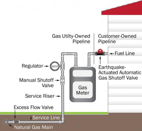
Natural gas is odorless until we add mercaptan, an odorant similar to rotten eggs, to help detect leaks. If you smell natural gas or have a natural gas emergency, leave immediately and call us from another location.
We survey for possible leaks on our distribution mains every year in populated communities and every other year in more rural areas. (Federal requirement for main surveys is once every five years).
All of our 1 million customer service lines are inspected within every three years. (Federal requirement for service line surveys is once every five years).
We have corrosion protection on all steel pipe in our system. (Federal requirement requires corrosion inspections only on pipes installed prior to 1971.)
Wisconsin limits distribution system operating pressure at 60 psig (pounds per square inch). (Federal limit allows for distribution systems to operate at 125 psig.)
Each year, we sponsor contractor workshops to reinforce safety guidelines for construction crews that work around natural gas and electric facilities.

A little product education can make you look super smart to customers, which usually means more orders for everything you sell. Here’s a few things to keep in mind about safety valves, so your customers will think you’re a genius.
A safety valve is required on anything that has pressure on it. It can be a boiler (high- or low-pressure), a compressor, heat exchanger, economizer, any pressure vessel, deaerator tank, sterilizer, after a reducing valve, etc.
There are four main types of safety valves: conventional, bellows, pilot-operated, and temperature and pressure. For this column, we will deal with conventional valves.
A safety valve is a simple but delicate device. It’s just two pieces of metal squeezed together by a spring. It is passive because it just sits there waiting for system pressure to rise. If everything else in the system works correctly, then the safety valve will never go off.
A safety valve is NOT 100% tight up to the set pressure. This is VERY important. A safety valve functions a little like a tea kettle. As the temperature rises in the kettle, it starts to hiss and spit when the water is almost at a boil. A safety valve functions the same way but with pressure not temperature. The set pressure must be at least 10% above the operating pressure or 5 psig, whichever is greater. So, if a system is operating at 25 psig, then the minimum set pressure of the safety valve would be 30 psig.
Most valve manufacturers prefer a 10 psig differential just so the customer has fewer problems. If a valve is positioned after a reducing valve, find out the max pressure that the equipment downstream can handle. If it can handle 40 psig, then set the valve at 40. If the customer is operating at 100 psig, then 110 would be the minimum. If the max pressure in this case is 150, then set it at 150. The equipment is still protected and they won’t have as many problems with the safety valve.
Here’s another reason the safety valve is set higher than the operating pressure: When it relieves, it needs room to shut off. This is called BLOWDOWN. In a steam and air valve there is at least one if not two adjusting rings to help control blowdown. They are adjusted to shut the valve off when the pressure subsides to 6% below the set pressure. There are variations to 6% but for our purposes it is good enough. So, if you operate a boiler at 100 psig and you set the safety valve at 105, it will probably leak. But if it didn’t, the blowdown would be set at 99, and the valve would never shut off because the operating pressure would be greater than the blowdown.
All safety valves that are on steam or air are required by code to have a test lever. It can be a plain open lever or a completely enclosed packed lever.
Safety valves are sized by flow rate not by pipe size. If a customer wants a 12″ safety valve, ask them the flow rate and the pressure setting. It will probably turn out that they need an 8×10 instead of a 12×16. Safety valves are not like gate valves. If you have a 12″ line, you put in a 12″ gate valve. If safety valves are sized too large, they will not function correctly. They will chatter and beat themselves to death.
Safety valves need to be selected for the worst possible scenario. If you are sizing a pressure reducing station that has 150 psig steam being reduced to 10 psig, you need a safety valve that is rated for 150 psig even though it is set at 15. You can’t put a 15 psig low-pressure boiler valve after the reducing valve because the body of the valve must to be able to handle the 150 psig of steam in case the reducing valve fails.
The seating surface in a safety valve is surprisingly small. In a 3×4 valve, the seating surface is 1/8″ wide and 5″ around. All it takes is one pop with a piece of debris going through and it can leak. Here’s an example: Folgers had a plant in downtown Kansas City that had a 6×8 DISCONTINUED Consolidated 1411Q set at 15 psig. The valve was probably 70 years old. We repaired it, but it leaked when plant maintenance put it back on. It was after a reducing valve, and I asked him if he played with the reducing valve and brought the pressure up to pop the safety valve. He said no, but I didn’t believe him. I told him the valve didn’t leak when it left our shop and to send it back.
When it came back, I laid it down on the outlet flange and looked up the inlet. There was a 12″ welding rod with the tip stuck between the seat and the disc. That rod was from the original construction and didn’t get blown out properly and just now it got set free. The maintenance guy didn’t believe me and came over and saw it for himself (this was before cell phones when you could take a picture).
If there is a problem with a safety valve, 99% of the time it is not the safety valve or the company that set it. There may be other reasons that the pressure is rising in the system before the safety valve. Some ethanol plants have a problem on starting up their boilers. The valves are set at 150 and they operate at 120 but at startup the pressure gets away from them and there is a spike, which creates enough pressure to cause a leak until things get under control.
If your customer is complaining that the valve is leaking, ask questions before a replacement is sent out. What is the operating pressure below the safety valve? If it is too close to the set pressure then they have to lower their operating pressure or raise the set pressure on the safety valve.
Is the valve installed in a vertical position? If it is on a 45-degree angle, horizontal, or upside down then it needs to be corrected. I have heard of two valves that were upside down in my 47 years. One was on a steam tractor and the other one was on a high-pressure compressor station in the New Mexico desert. He bought a 1/4″ valve set at 5,000 psig. On the outlet side, he left the end cap in the outlet and put a pin hole in it so he could hear if it was leaking or not. He hit the switch and when it got up to 3,500 psig the end cap came flying out like a missile past his nose. I told him to turn that sucker in the right direction and he shouldn’t have any problems. I never heard from him so I guess it worked.
If the set pressure is correct, and the valve is vertical, ask if the outlet piping is supported by something other than the safety valve. If they don’t have pipe hangers or a wall or something to keep the stress off the safety valve, it will leak.
There was a plant in Springfield, Mo. that couldn’t start up because a 2″ valve was leaking on a tank. It was set at 750 psig, and the factory replaced it 5 times. We are not going to replace any valves until certain questions are answered. I was called to solve the problem. The operating pressure was 450 so that wasn’t the problem. It was in a vertical position so we moved on to the piping. You could tell the guy was on his cell phone when I asked if there was any piping on the outlet. He said while looking at the installation that he had a 2″ line coming out into a 2×3 connection going up a story into a 3×4 connection and going up another story. I asked him if there was any support for this mess, and he hung up the phone. He didn’t say thank you, goodbye, or send me a Christmas present.
Pipe dope is another problem child. Make sure your contractors ease off on the pipe dope. That is enough for today, class. Thank you for your patience. And thank you for your business.

— Pressure safety relief valves are typically used to control pressure on boilers in heating systems, on stored hot water cylinders in domestic hot water systems, and generally in water systems. T&P relief Valve Function:
This is caused by water expanding during the heating cycle. The T/P valve will then relieve pressure by releasing hot water drips to the drain line. It is recommended that an expansion control valve be fitted to the cold water supply line to reduce cold water(not hot water) during the heating cycle expansion, thereby saving energy and increasing the life of the T&P relief valve. Local regulations may require installing an expansion control valve in the cold water supply line.
With so many brass pressure relief valves to choose from, it can be challenging to find the right one. Whether you are looking for a valve that has a higher flow rate or is more durable, here are some essential things to consider when choosing your next brass pressure relief valve:
Once you have answered these questions, you can narrow your search for the perfect brass pressure relief valve. For example, if you have a system that operates at a high PSI, you will need a valve to withstand higher pressures. Conversely, if you have a minor piping system, you may consider a valve with a lower flow rate.
Always read the manufacturer’s instructions carefully before installing, no matter what type of valve you choose. By following these simple guidelines, you can be confident that your new brass pressure relief valve will provide years of reliable service.
Answering these questions will make it easier to narrow your search for the perfect brass pressure relief valve. For example: if you have a more extensive piping system with high operating pressures, you may want to consider one that can handle higher flow rates and has extra features (such as a pilot light). Conversely, if you choose between two valves that can withstand up to 150 PSI but only differ by 0.25 GPM in their flow rate, then maybe select based on price alone. The key here is knowing what factors matter most when purchasing something like this, so don’t be afraid to ask for help from a qualified technician.
Like anything else, it’s essential to read the manufacturer’s instructions carefully before installation. Following these guidelines ensures that your new brass pressure relief valve will provide years of quality service!
Once you have chosen the perfect brass pressure relief valve for your system, it is essential to install it properly. These instructions are based on a typical installation with similar-sized piping and valves. The first step in choosing an appropriate location for installing your new valve will be finding out what type of piping system you currently have.
Depending on the answer, there may or may not be any further steps required before moving on to the next section: Determining pipe size. If this was already calculated during Step One (piping systems), then proceed directly here; if not, please continue reading below:
Most sizing charts that can help determine pipe sizes generally refer back to either inch-pound units or PSI; depending on where you live, one of these measurements will be more common. To convert your pipe size into PSI, you can use this online calculator or do it by hand:
Once you have determined the pipe size in PSI, it is time to find what pressure relief valve will work with your system. Now that you know the piping system and pipe size, finding a brass pressure relief valve should be as easy as pie!
Compressed gases are stored in heavy-walled metal cylinders designed, produced and tested for use with compressed gases. Cylinders are made in a wide variety of sizes and shapes. They range from small lecture bottles, often used for demonstration purposes, to large cylinders over 3 metres long. Cylinders for transportation must meet CSA standard CAN/CSA-B339 "Cylinders, Spheres and Tubes for the Transportation of Dangerous Goods". This standard covers requirements for the manufacturing, inspection, testing, marking, requalification, reheat treatment, repair, and rebuilding of cylinders, spheres, and tubes (containers) for the transportation of dangerous goods. In addition, it includes the requirements for the qualification of new designs and registration requirements. You should also consult CAN/CSA-B340 "Selection and Use of Cylinders, Spheres, Tubes, and Other Containers for the Transportation of Dangerous Goods, Class 2".
Cylinders that meet these criteria are often referred to as "TC approved" cylinders. Cylinders are permanently marked, typically on the shoulder or the top surface of its neck.
Compressed gas cylinders must be connected only to regulators and equipment designed for the gas in the cylinder. Since connecting the wrong equipment can be dangerous, a number of different standard cylinder valve outlets are available for different classes of gas. For example, these standard connections prevent the valve connection for a flammable gas from fitting the connections for an incompatible gas, such as an oxidizing gas.
Most compressed gas cylinders have valve caps or some other method of protecting the valve from damage during handling and transportation. A dust cap may be placed over the valve outlet itself to help keep it clean.
Most cylinders have one or more safety-relief devices. These devices can prevent rupture of the cylinder if internal pressure builds up to levels exceeding design limits. Pressure can become dangerously high if a cylinder is exposed to fire or heat, including high storage temperatures.
There are three types of safety-relief devices. Each relieves excessive gas pressures in a different way:Safety- or Pressure-Relief Valves: These valves are usually a part of the cylinder. They are normally held closed by a spring. The force holding the valve closed is set according to the type of gas in the cylinder. The valve opens if the cylinder pressure exceeds the set safety limit. Gas is released until the cylinder pressure drops back to the safety limit. The valve then closes and retains the remaining gas in the cylinder.
Rupture Discs(also known as frangible or bursting discs): These discs are usually made from metal. They burst or rupture at a certain pressure, releasing the gas in the cylinder. The bursting pressure is designed so that the disc ruptures before the cylinder test pressure is reached. These devices cannot be reclosed, so the entire contents of the cylinder are released.
Fusible Plugs(also called fuse or melt plugs): Temperature, not pressure, activates fusible plugs. These safety devices are used where heat could initiate an explosive chemical reaction. A pressure-relief valve or rupture disc acts too slowly and too late to prevent rupture of the cylinder if an explosive reaction has already begun. The fusible plug releases the gas before the hazardous reaction can begin. Fusible plugs are made of metals that melt at low temperatures. For example, acetylene cylinders have a fusible plug which melts at about 100°C (212°F). This temperature is safely below the temperature at which hazardous polymerization may occur.
Not all compressed gas cylinders have safety devices. Some gases are so toxic that their release through a safety device would be hazardous. Cylinders for these gases are built to withstand higher pressures than normal cylinders. When these "toxic gas" cylinders are involved in a fire, the area must be evacuated.
Substitution can be the best way to avoid or reduce a hazard. But it is not always easy or even possible to find a less hazardous substitute for a particular compressed gas used for a certain job. Speak to the chemical supplier to find out if safer substitutes are available. For example, in some cases, methylacetylene-propadiene (MAPP) gas, propylene, propane or mixtures of liquefied petroleum gas can be substituted for acetylene as fuel gases for cutting, welding and brazing. These gases are more stable and can be stored in normal cylinders. Their flammable limits are much narrower than those of acetylene (e.g., 3.4 to 10.8 percent for MAPP versus 2.5 to 82 percent for acetylene), so they represent a reduced fire hazard.
Obtain MSDSs for all possible substitutes. Find out about all of the hazards (health, fire, corrosivity, chemical reactivity) of these materials before making any changes.
Sometimes, process changes or modifications can reduce a material"s hazards. For example, many cylinders of the same gas may be used in different areas of a workplace. Installing fixed pipelines connected to a central gas supply in a safe area can often reduce the hazard. It can also reduce the need for many sets of portable equipment supplied through flexible hoses. Similarly, ordering cylinders equipped with flow limiting restrictors can minimize the hazards of a sudden failure of a process gas line.
The amount and type of ventilation needed depends on such things as the type of job, the kind and amount of materials used, and the size and layout of the work area.
Assess the specific ways your workplace stores, handles, uses and disposes of its compressed gases. An assessment can reveal if existing ventilation controls and other hazard control methods are adequate. Some workplaces may need a complete system of hoods and ducts to provide acceptable ventilation. Others may require a single, well-placed exhaust fan. Storage facilities for particularly hazardous materials such as chlorine, may require an additional emergency ventilation system, or continuous monitoring with appropriate alarms. Other workplaces using small amounts of inert gases may require no special ventilation system.
Make sure ventilation systems are designed and built so that they do not result in an unintended hazard. Ensure that hoods, ducts, air cleaners and fan are made from materials compatible with the gas used. Systems may require explosion-proof and corrosion-resistant equipment. Separate ventilation systems may be needed for some compressed gases to keep them away from systems exhausting incompatible substances.
Store compressed gas cylinders in compliance with the occupational health and safety regulations and fire and building codes applying to your workplace. These laws may specify the permissible kinds of storage areas and the construction of these storage areas. They may also specify the kinds and amounts of different gases that can be stored in each safe storage area.
Inspect all incoming cylinders before storing to ensure they are undamaged and properly labelled. Do not accept delivery of defective cylinders. Be sure they are not giving off odours, visible fumes or hissing sounds. Check that the cylinder was last tested within the required time (usually 5 or 10 years, but some containers may be as lo


 8613371530291