
hydraulic cylinder safety valve supplier
An auxiliary passage, which is where the relief valve sends the extra liquid or gas to relive the pressure in a mechanism, is usually just an extra pipe that leads to a chamber where most likely the fluid is burned and the gas left over is released into the atmosphere. This is a particular necessity in the chemical and petrochemical manufacturing industry, as well as in petroleum refining plants, natural gas processing and power generation industries.
If the pressure in a hydraulic pump exceeds its designed pressure limit, internal leakage or damage to the pump components can occur. Depending on what the liquid is, such leaks could also cause serious damage to individuals in the vicinity and the environment.
In hydraulic control systems, the relief valve acts as a check valve, with a ball and an adjustable spring. When a relief valve opens to divert fluid into an auxiliary passage, the pressure inside the hydraulic cylinder drops and allows the valve to close. A hydraulic system will often employ several types of valves, although the hydraulic relief valve is usually the first encountered in the circuit.
Hydraulic relief valves can be found in almost any mechanism that runs on hydraulic power, such as automobile transmissions, brakes, power steering, aviation and in industrial and construction machinery. Relief valves are built from the same basic materials that most hydraulic valves are made from. The strong and corrosion resistant metals that are most common are stainless steel, aluminum, iron, brass and copper.
Aluminum and stainless steel are thin, light weight and flexible, while still retaining the strength necessary to control the flow of liquid. Usually when a heavy metal like iron is used for the body of a valve, one of those two lighter metals is still used for the disc or plunger.
Plastic is also used, particularly thermoplastics that are developed specifically to be used as valve material. Although they are not as resistant to corrosion as metal, they are cheaper. It"s all about options.

Valves are used to continue and discontinue flows, modify flow rates, reroute the direction of a flow, and regulate or relieve pressure (among similar purposes). Due to the wide variety of valve types, several different methods of classifying valves exist. It should be noted that the term hydraulic valve specifically refers to the application of a specific type of valve. In other words, a hydraulic valve is simply any type of valve that acts on hydraulic fluid
Hydraulic systems have existed in some way or another since the sixth century BC, when the Mesopotamians and Egyptians used water power for irrigation. Use of hydraulics was also seen in the Hellenistic age and in ancient Persia, China, Sri Lanka, and Rome. The modern age of hydraulics began in the early 1600s, with the innovations of scientists like Benedetto Castelli and Blaise Pascal. Pascal, in particular, played a pioneering role in the field of modern hydraulics.
Pascal’s law summarizes the basis upon which the principles of hydraulics are founded. In essence, this law states that when pressure is placed on any point of a confined liquid, such pressure will transmit equally to all other parts of the confined liquid. Correspondingly, if pressure increases at any point in a confined liquid, equal and proportional increases will appear at all other points in the confined liquid. It is important to note that Pascal’s Law is made possible by the fact that liquid is incompressible. It is equally important to note that is does not apply to liquids which are not confined in some type of enclosed area. Using this principle, engineers and scientists have successfully designed systems that generate, control, and transfer power via pressurized fluids, eliminating much need for manual human effort. (Fuller explanations of Pascal’s Law can be found at treatments of other hydraulic parts, including our sites on hydraulic pumps and hydraulic cylinders).
Most hydraulic valves minimally consist of a main casing, a bonnet, a seat, and a disc. The main casing is the valve’s outer enclosure; it contains all the internal components, which are collectively called the trim. Most often, the casing is made from a metallic or plastic material. Common metallic materials include steel, stainless steel, alloyed steel, cast iron, bronze, brass, and gunmetal (red brass), while among the most common plastic options are PVC, PVDF, PP, and glass-reinforced nylon.
The bonnet is a semi-permanent, removable part of the valve that acts as a cover. For access to interior parts of the valve, the bonnet needs to be removed. Some valves do not have a bonnet because of the way they are constructed. (One example of such a valve is a plug valve.)
Hydraulic valves can only be properly understood within the context of entire hydraulic systems. An entire unit that generates power hydraulically is known as a hydraulic power pack or a hydraulic power unit. Such packs or units typically consist of a reservoir, a pump, hydraulic valves, and hydraulic actuators such as motors or cylinders.
The purpose of hydraulic valves within a hydraulic power pack is to connect the power source (i.e., the pump) to the actuators which translate hydraulic power into mechanical motion (i.e. hydraulic cylinders, hydraulic motors). Through its valves, a hydraulic power system can supply its actuators with hydraulic fluid and modify the flow of such fluid as needed.
While functional, valves generally have at least two settings: open and closed. Generally speaking, fluid may flow freely through the valve if it is open. Conversely, fluid flow is restricted if the valve is closed. Valves with a default status of open are also known as open center valves, while valves with a default status of closed are known as closed center valves.
Valves are either open or closed based on the positioning of their interior pieces; more specifically, a valve’s status depends on whether or not the disc is inside the seat. Hydraulic valves (and especially ones used for directional control) are often referred to as spool valves since they visually resemble spools of thread (by containing interior trim within exterior housing). The flow of hydraulic fluid (or lack thereof) is dependent on the position of the interior “spool” portion of the valve within the exterior housing. The default or “neutral” position of many valves has the spool in a central position which blocks the flow of hydraulic fluid. In order to open the valve and let fluid through, the spool simply slides to one side of the housing and away from the neutral position. Nowadays, many hydraulic valves also allow for partial flow obstruction.
As alluded to in the introduction, hydraulic valves can be categorized in several different ways. Some methods of categorization emphasize a valve’s physical characteristics or construction. Other methods emphasize a valve’s method of actuation or control. Still other categorization methods classify hydraulic valves according to their specific application or function.
A common way to label hydraulic valves is by its number of ports. The term port simply refers to an avenue that hydraulic fluid can use to flow into or out of a valve. Standard hydraulic valves are double port, since they possess both an inlet port (to draw in fluid from the pump) and an outlet port (to pass fluid on to the actuators). However, hydraulic valves can also be three-port, four-port, or multi-port. Hydraulic manifolds are another type of valve which is classified primarily on the basis of physical characteristics. Such mechanisms are actually separate hydraulic valves that are connected to one another within hydraulic systems.
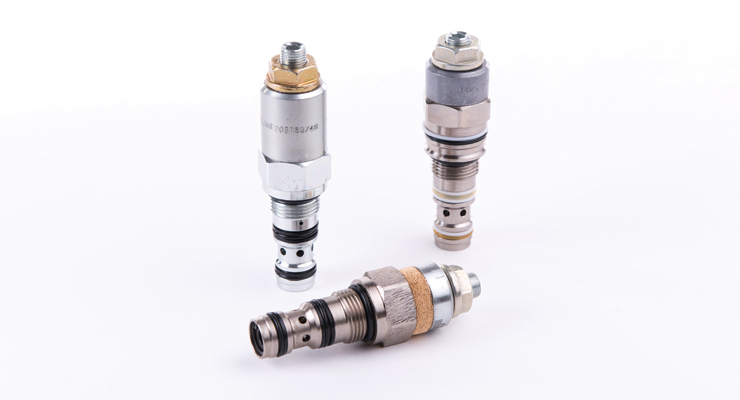
Hydraulic cartridge valves (also known as slip in valves, logic valves, or 2/2-way valves) are some of the more popular valves which derive their classification from their configuration. These valves are screwed into a threaded cavity and are typically composed of only a sleeve, a cone or poppet, and a spring. They open when incoming fluid pushes the holding cone or poppet (held in place by the spring) aside. The ease of installing cartridge valves makes them very popular in the hydraulic world.
Overall, hydraulic valves vary widely in physical shape and size. They can range in size from less than an inch to a foot long. On average, they can fit in the palm of a hand. The broad physical variety that characterizes hydraulic valves directly affects their differing uses.
It is important to note that valves can only function properly with some type of valve actuator. While not strictly a part of the valve itself, valve actuators are important since they are responsible for actually moving the machinery within a valve to change its status. Valve actuators can be either manual or automatic.
An example of a manually operated valve is the hydraulic ball valve. This valve derives its name from a spherical, internal disk containing a hole and is activated with a handle that can be quickly rotated 90° between opened and closed positions. When the valve is open, the hole in the ball disk lines up with the direction of fluid flow and allows fluid to pass through. When the valve is closed, the hole is not lined up with the fluid flow, thus blocking the flow of fluid.
Valve balls are perforated and most often made of nickel, brass, stainless steel, or titanium. (Sometimes, they are composed of a plastic, like PVC, PP, ABS, or PVDF.)
Many manually operated hydraulic valves typically require high amounts of force in order to successfully stop high-pressure flows of hydraulic fluid. Thus, many manual hydraulic valves other than ball valves are operated by oversized wheels, levers, and even hydraulic rams.
Other hydraulic valves are electrically operated, and/or guided remotely with computer controls. Hydraulic solenoid valves are an excellent example of such valves. They open and close based on the charge of a magnetic field that pushes on a plunger. The magnetic field is signaled by a current, which is received by a wire coil when the solenoid converts electrical energy into mechanical energy. Other types of electronically or remotely controlled hydraulic valves can be found in places such as construction sites, where they are critical to the operation of many hydraulically-powered construction machines.
Overall, mechanical valves in general are often classified by the exact function they are designed to exact on a fluid (e.g. completely cutting off a flow, preventing backflow, etc.). Since hydraulic valves are essentially general types of valves expressly applied in hydraulic scenarios, hydraulic valves are often also classified according to their exact regulatory function.
Control valves are valves specifically designed to control or modify the amount and speed of a fluid flow. These types of valves are particularly capable of occupying a spectrum of positions between fully open and fully closed. They are sometimes further classified as pressure control valves and flow control valves. (Control valves contrast with simple on/off valves or shutoff valves, which are designed to completely stop or start a fluid flow rather than simply modifying it.)
Directional control valves (or simply directional valves) may arguably be the “basic” type of mechanical valve, since their purpose is to control or modify the direction (rather than the amount) of fluid flow. On average, many standard hydraulic “spool” valves are used expressly for directional control and occupy a few discrete positions. Check valves (or non-return valves) are specific types of directional control valves that are used to force fluid flow in one direction only; if fluid within a hydraulic system somehow begins flowing in an undesirable direction, the check valve will close and block the flow. Check valves are critical to hydraulic systems in environments where substances of varying compositions and pressures must be kept separated (such as wastewater management plants).
Proportional valves can be considered as “extensions” of directional control valves. In addition to modifying flow direction, these type of valves can occupy intermediate positions and carry an output flow that is unequal to the input flow. In other words, proportional valves are designed to control the speed as well as the direction of fluid flow. (From this perspective, they can also be considered as extensions of control valves, which are designed to control the speed and amount of fluid flow.)
Pressure relief valves (or simply relief valves) are primarily designed to keep hydraulic systems from over-pressurizing. Instead of closing when undesirable conditions are met (such as check valves), these types of valves open in order to draw hydraulic fluid back into the reservoir when internal pressure has exceeded a certain point (e.g. due to a blocked pipe in the system).
It should be noted that differing functions accomplished by the aforementioned valves can also be performed by other, more specific types of valves. For example, hydraulic cartridge valves are often used for directional or check control as well as pressure or flow control. Beyond these few examples, there are many other unique valve types with individual functions. Hydraulic needle valves, for instance, are composed of small ports and threaded plungers. Their unique shape allows them to regulate flow in extremely tight spaces.
Other components associated with hydraulic valves include springs, gaskets, and stems. Those valves that include springs do so in order to shift the disc and control repositioning. Common spring materials include stainless steel, zinc-plated steel and, for work with exceptionally high temperatures, Inconel X750. Gaskets are mechanical seals, usually made from an elastomer. Their purpose is to prevent leakage of fluids from the valve or in between separate areas of the valve. The term metal face seal refers to a gasket that is located between two fittings in a sandwich-like arrangement. Stems are not always present, because they are often combined with the disc or handle. However, when present, they transmit motion from the controlling device, like the handle, through the bonnet and to the disc.
Hydraulic valves can be connected to hydraulic systems with a variety of different mechanisms. Some of these mechanisms include flanges (bolt or clamp), welds (butt or socket), union connections, and fittings (tube or compressions).
The value of hydraulic valves to the industrial world is inextricably bound up in the value of hydraulic systems as a whole. Overall, hydraulic power systems offer energy sources that are simpler and safer than other types (such as electrical power systems) while still being incredibly effective. Hydraulic valves are thus valued and widespread because they enable effective movement of hydraulic fluid, which forms the “lifeblood” of hydraulic power systems.
Hydraulic valves make flow control possible for many, many applications, including those in the aerospace, automotive, chemical and laboratory, construction, cryogenic, fire and heating services, food processing, fuel and oil, gas and air, irrigation, medical, military, process control, refrigeration, and wastewater industries.
Since hydraulic valves vary so widely, it can be difficult determining the correct valve for a specific application. The below points offer a brief sketch of various factors to keep in mind during the determination process.
• What type of flow coefficient is best for this application? A hydraulic valve’s flow coefficient is a combined measure that indicates the amount of energy that is lost by fluid as it flows through or across the valve. Different valves possess differing coefficients, and similar valves can diverge in flow coefficients if their diameter (often measured in inches) is different. Generally speaking, higher flow coefficients indicate lower drop pressures that occur across the valve (if the flow rate remains the same). Determining the proper flow coefficient is one of the best methods to determine the proper valve to use in a given scenario. For example, a valve with a low head loss (one of the combined measures that makes up a flow coefficient) to conserve energy is best in a scenario where the valve will be normally open rather than closed. Hydraulic cartridge valves are popular in scenarios where energy needs to be conserved, since they cause far less energy and/or pressure loss than other types of valves.
• What is the maximum temperature you will reach in a given hydraulic scenario? Different types of hydraulic valves are designed to handle different maximum temperatures. You will want to investigate the maximum temperatures reached during your hydraulic operations and select hydraulic valves accordingly.
• How rigorous will my hydraulic application be? Some valves are better than others for high-intensity hydraulic situations. For example, valve balls are a common feature in hydraulic valves that are made for high pressure, high tolerance, and/or severe duty applications.
• How many ports or directional stages does my hydraulic scenario require? Although many times a standard double-port hydraulic valve will work, there may be times when a multi-port hydraulic valve is preferable.
Not all of the decisions that go into hydraulic valve selection need to be made alone. Investing in a quality hydraulic parts manufacturer or supplier is well worth the cost the majority of the time. Some characteristics of hydraulic parts suppliers to look for include:
• Adherence to hydraulic industry standards. This characteristic will be closely tied to a company’s level of accreditation. Some specific ISO standards to look for include ISO 6403 (flow and pressure valves), ISO 6263 (hydraulic fluid power and mounting surfaces), SAE J748 (hydraulic directional control valves), and SAE J1235 (standards for reporting the hydraulic valve leakage)
• Depth of experience/expertise. Sometimes, a supplier may regularly offer only a small selection of hydraulic valves. However, a supplier’s level of industry expertise may be able to offset this reality and provide you with customized hydraulic valves as needed.
• Turnaround time. All types of industrial breakdowns are undesirable, but the failure of power systems (hydraulic and otherwise) is particularly undesirable. If your hydraulic power system fails due to valve trouble, you want to be sure you are working with a supplier that can advise on and provide needed replacements in record time.
![]()
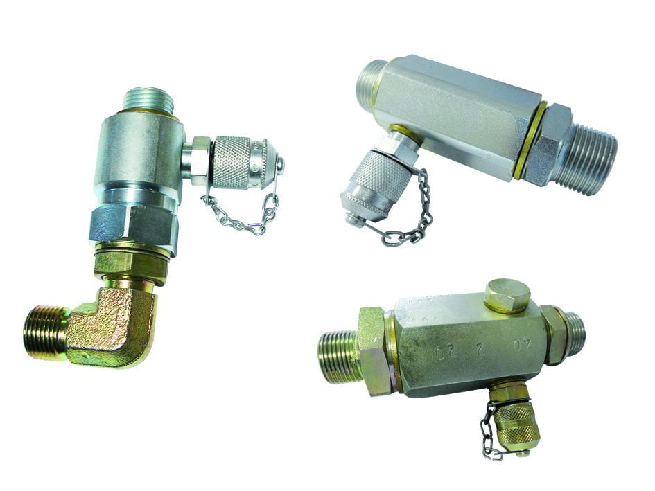
Hydraulic relief valves are used to limit the pressure in a hydraulic system. They achieve this result by allowing the pressurized hydraulic fluid to flow out of the system into an auxiliary passage.
In hydraulic control systems, the relief valve acts as a check valve, with a ball and an adjustable spring. When a relief valve opens to divert fluid into an auxiliary passage, the pressure inside the hydraulic cylinder drops and allows the valve to close. A hydraulic system will often employ several types of valves, although the hydraulic relief valve is usually the first encountered in the circuit. Hydraulic relief valves can be found in almost any mechanism that runs on hydraulic power, such as automobile transmissions, brakes, power steering, aviation and in industrial and construction machinery.
Relief valves are built from the same basic materials that most hydraulic valves are made from. The strong and corrosion resistant metals that are most common are stainless steel, aluminum, iron, brass and copper. Aluminum and stainless steel are thin, lightweight and flexible, while still retaining the strength necessary to control the flow of liquid. Usually when a heavy metal like iron is used for the body of a valve, one of those two lighter metals is still used for the disc or plunger. Plastic is also used, particularly thermoplastics that are developed specifically to be used as valve material. Although they are not as resistant to corrosion as metal, they are cheaper. It’s all about options.
Hydraulic relief valves protect hydraulic systems from being exposed to high pressures that exceed the mechanism"s specified limits. A relief valve is placed at the entrance to a separate tube and is set to only open when a certain amount of pressure is applied, which can only be applied if there is too much liquid or gas in the chamber or pipe. An auxiliary passage, which is where the relief valve sends the extra liquid or gas to relieve the pressure in a mechanism, is usually just an extra pipe that leads to a chamber where most likely the fluid is burned and the gas left over is released into the atmosphere.
This is a particular necessity in the chemical and petrochemical manufacturing industry, as well as in petroleum refining plants, natural gas processing and power generation industries. If the pressure in a hydraulic pump exceeds its designed pressure limit, internal leakage or damage to the pump components can occur. Depending on what the liquid is, such leaks could also cause serious damage to individuals in the vicinity and the environment.

Hydraulic valves are used to direct and control the flow of fluids through a system of pipes, hoses, or cylinders, converting the fluid force into mechanical energy. This energy is transmitted through the hydraulic system by a series of accumulators, pumps and actuators to operate a wide range of equipment for a vast array of functions. They are generally part of a "closed loop" system with a reservoir, that allows the fluid to expend its driving force before being returned to the reservoir for continuous function.
All of these grounding theories were pertinent to the advancement of hydrostatics (water at rest) and hydrodynamics (water in motion), paving the way for hydraulic (water powered) developments.
In 1648, Frenchman Blaise Pascal presented the Hydrostatic Transmission Theory claiming that pressure applied to a static fluid is transmitted equally in all directions. Now known as Pascal"s Law, this theory is the fundamental basis of hydraulics.
Joseph Bramah patented the first hydraulic machine in 1795. It was an industrial press with designs still in use. His progress was followed by the likes of Robert Boyle, Sir Isaac Newton, Daniel Bernoulli, and Leonhard Euler, all of whom lent their knowledge to the field of hydraulics.
Around 1907, Harvey Williams and Reynolds Janney developed the first axial piston devices, which were both pumps and motors, that used the fluid medium as a lubricant. Water was not an adequate medium, so oil hydraulics came into existence, nearly obliterating the water hydraulic industry.
In 1956, a misplaced mining wagon ruptured a hydraulic oil line and severed an electrical line at a mine in Belgium. The ensuing fire killed 262 people, inciting new legislation that required mines and manufacturers to use water hydraulics for safety reasons. These systems are still considered a safe, effective alternative to oil hydraulics. Both systems are in use today.
Most hydraulic valves are made from iron, brass, steel, or stainless steel. Smaller units may be made from plastics. The seat, or outer housing of a valve, and the body, or inner component that opens and closes the channel, may be cast, die forged, or machined. An external wheel or lever is incorporated with the body to operate it.
Basic hydraulic valves have two stations: open and closed. When closed, no fluid is able to pass through but when open, it flows freely. Hydraulic valves are used within a fluid control system as a simple way to prevent improper levels of pressure and fluid. The simplest hydraulic valve uses two equally sized pistons in two cylinders connected by a pipe filled with hydraulic fluid. When force is applied to one piston, the other rises. Because the fluid can not be made smaller, it is considered incompressible, and may only be displaced. This means that the pipe containing the hydraulic fluid may be any size, shape, or configuration. As long as it is full and no compressible air bubbles are present, pressure applied at one end will result in virtually equal force at the other end.
Hydraulic power transmission is very effective. It may be divided through the use of a manifold and subsequent slave cylinders that are operated by a master cylinder. The most prevalent example of this is the braking system on an automobile. One pedal operates the brakes on all four wheels at the same time.
The force at the business end of a hydraulic valve may be "stepped up" or "stepped down" by changing the size of one piston and cylinder in a process of hydraulic multiplication or division. For example: a two inch diameter cylinder with a nine inch long piston will raise another two inch diameter piston nine inches with an applied force of one hundred pounds.
If the second piston has a diameter of six inches, it has a surface area nine times larger than the two inch piston. The smaller piston will only move the larger piston one inch in distance, but the resulting force is multiplied by nine, providing nine hundred pounds of pressure from one hundred pounds of initial force. Mathematical formulas may be applied to calculate accurate valve sizes and configurations for any hydraulic system.
Some valves shut off flow when flow rates get too high, while others transmit signals to other valves in order to provide a systematic balance of flow. These valves protect hydraulic systems from being exposed to high pressures that exceed the mechanism"s specified limits. The solenoid converts electrical energy into mechanical energy. When the wire coil receives a current, a magnetic field acts upon the plunger, which results in opening or closing of the valve. Hydraulic check valves have two openings: an inlet in which the fluid enters and an outlet through which the fluid exits. They prevent backflow. Hydraulic directional control valves permit flow in more than one direction because they have a component that shifts or rotates to line up with the corresponding pipes or tubes and accommodate a number of ports. Hydraulic control valves prevent improper levels of pressure and fluid in hydraulic systems. Hydraulic relief valves are used to limit the pressure in a hydraulic system by allowing the pressurized hydraulic fluid to flow out of the system into an auxiliary passage. Protecting the passage of the substance as well as the environment through which it is passing is the overall goal of hydraulic valves, as well as protecting the substance and its source.
The type of hydraulic control valve placed in the system will depend on the specifications of the job. Some valves such as ball valves, butterfly valves, globe valves, check valves, and gate valves are simple flow control valves that are generally either fully open or completely shut.
Parts that control the flow and pressure of a fluid by using a spherical element to create a seal. Ball valves are used in critical high pressure applications that require a quick and easy shutoff.
Used to contain and transfer the flow and pressure of hydraulic fluid in hydraulic systems. There are many different designs of hydraulic control valves, including check, cartridge, directional, relief, safety, shut off, and hydraulic solenoid valves. Hydraulic control valves come in a variety of sizes and pressure ratings.
Control the direction of the hydraulic fluid to the point where it is needed. Directional control valves are useful for hydraulic tools and farm equipment that use hydraulics.
Valves that automatically open or close as the liquid level changes. Float valves are operated mechanically by a float that rests on top of the liquid.
Linear motion valves in which a flat closure element slides into the flow stream to provide shut-off. Gate valves are designed to minimize pressure drop in fully open positions.
Multi-turn valves that have a closing element that moves perpendicular to the valve body seat and generally seals in a plane parallel to the direction of flow. This type of valve is suited both for throttling and general flow control.
Devices that regulate fluid flow between components in a hydraulic system. They let an operator know how much fluid is flowing between the pump and actuators, the hydraulic devices that move or control a mechanism.
Have small ports with thin threaded plungers that allow for tight flow regulation in hydraulic systems. Though the flow rates are low, needle valves provide a steady and precise flow of fluid and are therefore used for calibration or flow regulating applications.
Also known as a directional valve or directional control valve, is used as a switching device to control hydraulic equipment. It blocks and opens fluid pathways inside the valve to activate power transmission. It is a cylinder with a cutaway view resembling a thread spool, sealed inside a casing. Valves on one side lead to a pump and storage tank. Other valves may lead to a single device, or to a hydraulic manifold which directs power to multiple devices. The controller moves the spool into different positions, moving the fluid through the system. Pressure flows either from the pump to the devices or from the devices back into the fluid reservoir, but only provides force in one direction, depending on the position of the spool, which determines whether the force pushes or pulls.
Regulates the output pressure in a system with multiple hydraulic lines. Commonly found as components of braking systems for cars, p valves provide less pressure to rear brakes to keep them from locking up.
An electromechanical valve. An electrical current is run through a coil which creates a magnetic field. This causes a plunger to open or close the valve. Solenoid valves may be direct-acting, in which case the plunger opens and closes an internal orifice directly, or they may be pilot-operated, also known as servo-type valves, wherein the plunger operates a pilot orifice. Fluid pressure in the line passing through the pilot orifice operates the valve seal. Most s valves have an inlet port and an outlet port, classifying them as two port valves, although they may be designed with more outlet ports. Because they are controlled with electricity, they can be computer programmed to operate systems automatically.
Also known as logic valves and 2/2 valves, are threaded inserts that screw into a cavity in a manifold or a valve body. They may be used to control flow rate, direction, or pressure.
Directional control valves that only allow hydraulic fluids to flow one way. They are two port valves, meaning they have one inlet and one outlet, that are opened by the pressure of the fluid flow within, and shut by any backpressure that flows back into the pipe.
Types of safety valves designed to release pressure once it has built to a specific point. In equipment operation, hydraulic relief valves will relieve pressure by sending excess hydraulic fluid back to the storage tank. These valves may be pressure activated or spring loaded. Commonly found on water heaters, a safety relief valve will vent steam if the water in the tank gets too hot.
A type of pressure relief valve that are easily identified by their rapid opening and closing, which is directly proportional to increases in pressure.
Hydraulic valves are used in cars to actuate brakes, clutches, and gears. They are used in engine lubrication and air conditioning systems. Some car jacks use hydraulic cylinders to provide lift. The Jaws of Life utilize a system of hydraulic piston rods that can cut, spread, push, or pull a vehicle apart to rescue passengers.
Some hydraulic valves can handle several thousands of pounds per square inch of pressure and are found in heavy equipment operation. They control dump beds on trucks, swing arms on backhoes, blade adjustments on graders, track drives, conveyors, scissor lifts, and forklifts. Hydraulic valves are found in all industrial timber cutting and processing equipment, water and sewage treatment facilities, power plants, mining operations, oil, gas, and petroleum works, food harvesting, processing, and packaging operations, chemical processing plants, and plastics manufacturing.
Hydraulic control valves can be used to operate tiny nano-bots that perform microsurgery with masterful precision as easily as they control crane booms that can lift railroad cars or place construction materials on catwalks hundreds of feet in the air. They are at the heart of manufacturing automation and robotics. Without hydraulic components, there would be no amusement parks or draw bridges, and many industries would be reduced to a crippling crawl.
One of the simplest hydraulic devices is the log splitter. It is driven by an engine, typically a four-stroke gas motor, attached to an oil pump. The pump pushes the oil into a spool valve that operates a ram. The spool valve moves fluid into the ram with "stepped up" force. The ram of the log splitter is a hydraulic cylinder, with a wedge at the head, which splits the wood as the operator applies pressure to the lever. A reservoir contains hydraulic oil. It is often equipped with a filter to maintain the cleanliness of the oil.
A gear pump is the most common type of pump found in hydraulic systems. It is a positive displacement pump and is used to move high-viscosity fluids continuously. The gears are housed inside the pump casing and are classified as external or internal depending on the configuration. Gear pumps use two spur gears that mesh together. One of the gears is driven by a motor, the other, called an idler, is driven by the first gear. The counter-rotation creates a void in the intake side, suctioning hydraulic fluid into the rotation and moving it out the exhaust port. Tight tolerances between gears prevent backflow.
The ram is a piston rod that is driven by the fluid being pumped through the spool valve. In the log splitter, the pump pushes oil against the ram, which applies increasing pressure to the log, until it splits. The lever is released, the oil returns to the accumulator, and the process may begin again.
In heavy equipment, a series of pumps and rams are inter-connected through hydraulic lines to perform heavy duty moving, lifting, digging, and farming. These same tools on a miniaturized scale can be trusted to perform delicate brain or eye surgery. The valves that operate multiple component systems can be computer controlled for accuracy and automation.
Wear gloves and safety glasses. Hydraulic fluids often contain chemicals that can irritate skin and eyes. A pinhole leak in the system can spray oil at very high pressure, injecting the oil into the skin. Accidental ingestion can cause grave illness.
Watch out for the environment. Conventional hydraulic oil is not environmentally friendly. There are options available that are. If alternatives don"t work for specific applications, make sure to handle the fluids responsibly.
The S50 Safety Shut Off valve is mainly used to avoid any damage to components as well as to avoid too high or too low pressure in the gas train. This could cause high financial losses and/or injured ...
Excavator pipe-rupture valves prevent uncontrolled cylinder movement in the event that a pipe or hose bursts. The ESV valve fulfills all of the requirements of the ISO 8643 and EN 474-5 ...
... base of an hydraulic cylinder, while the hose can be applied on the valve without any other components needed. The safety valves VUBA-DIN avoid an uncontrolled lowering ...
Hydraulic safety valves are made according to API 6A. When oil and gas leaking or firing, used for security protect on well site, the control system includes low pressure ...
Jereh Safety Valve is equipped with pneumatic, hydraulic or electric actuator, widely used in Christmas tree and surface manifold. In case of any emergency ...
The Cross series relief valves have been designed to give long life and smooth performance at an economical price. The hydraulically dampened poppet uses differential areas to provide minimal variations between opening and full flow pressures.

Custom DutyShipping from Taiwan to : United States (US)HS Code: 841221 (Hydraulic Cylinders)The Custom Duty Rate is: 0.0%(The rate is for your reference only. Please check it with your local DHL, UPS, or Fedex)

A hydraulic lift table platform is held in the raised position by permanent pressure in the hydraulic cylinders. In the event a hose ruptures, this pressure would drop abruptly and the platform would drop to the ground. Three different valve types are used to prevent this: pipe rupture safety valves, electric pilot-operated valves as well as hydraulic pilot-operated valves. Here you can get more information about the design of the valves and their advantages and disadvantages.
Nowadays, safety valves are used in almost every hydraulic scissor lift scissor lift table to prevent the platform from dropping. Attention should be paid to the use of appropriate valves to prevent a possible accident, especially if there are people working or moving about around the scissor lift .
The respective application determines which type of valve is used. For example, there is a big difference between a lift table, which is only used to lift loads, and an aerial work platform where people are allowed to ride along on the platform.
Lift table manufacturers use pipe rupture safety valves in most cases. These are inexpensive and already cover a large part of potential hazardous situations. Their low price is mainly due to their simple design and quick installation.
The main components of a pipe rupture safety valve are the housing, the closing flap and a spring mechanism. Pipe rupture valves are screwed directly into the hydraulic cylinder and react to a pressure difference between the supply line and the cylinders of the lift table.
If the pressure in the supply line drops, the spring mechanism closes the flow-through opening. The oil cannot flow out of the hydraulic cylinders, and the platform remains in its current position.
However, sufficient pressure difference is necessary for the pipe rupture safety valves to effectively prevent the oil flow. This is particularly problematic if the pressure loss is not due to a burst or torn hydraulic hose, but to a small leak in the hydraulic system. The pressure difference in the event of a leak is so small that the spring mechanism does not close the flow-through opening. Consequently, the platform cannot be held securely in the top position despite the pipe rupture safety valves.
If the pipe rupture safety valves have been triggered, they can only be opened again by raising the lift table again. This action of raising the lift table allows pressure to be built up in the supply line, which opens the closing flap against the spring mechanism. For this reason, the use of pipe burst safety valves on aerial work platforms is not permitted when there is no other way to get off the platform, as the lift table platform can only be lowered once the drive has been repaired.
Electrically actuated poppet valves are provided as electric pilot-operated valves. They are installed directly on the hydraulic cylinder of the lift table. If the valves are closed and the supply line of the lift table rips off, the oil volume can be kept safely in the cylinders.
These valves do not differ from other electrically operated 2/2-way valves. They have two switch positions, which can be adjusted by means of a coil and a spring.
Hydraulic lift tables are equipped with valves which are normally closed (NC). If no electrical voltage is applied to the operating coil, the spring presses the valve into the rest position. In this position the flow-through opening of the hydraulic valve is closed, which means no oil can be exchanged between the supply line and the cylinders of the scissor lift table. This ensures that the oil is kept safely in the cylinders in case a hose ruptures or if a pipe breaks. If the lift table needs to be moved, the operating coil is actuated, the valve opens and the platform can be raised and lowered.
Compared to pipe rupture safety valves, electric pilot-operated valves have a higher safety level. They hold the platform of the lift table safely and securely in position even if there is a small leak in the hydraulic circuit. This high level of safety is achieved by actuating or opening the valves only when a downward movement of the lift table platform is desired. In any other case, the valves are in the safe rest position. This also makes them qualified for applications with higher safety requirements.
But electric pilot-operated safety valves also have disadvantages too. Although installation is still very simple and flexible, it is more complex than with simple pipe burst safety valves. An additional control cable must be routed to each cylinder in the lift table to actuate the valves directly. Furthermore, the lift table"s susceptibility to faults increases, as with each additional element there is a new component that can be defective. In this type of valve, the coils in particular represent an additional, albeit small, risk of failure of the scissor lift.
In addition, a lift table usually has at least two hydraulic cylinders and consequently two electric pilot-operated valves. And although it is very unlikely that both valves or coils are defective at the same time, a defective coil leads to another problem. In the event of damage, only one hydraulic valve opens while the defective valve remains closed. The entire load of the lift table therefore only acts on one cylinder and is no longer evenly distributed. For this reason, it is important when using electric pilot-operated valves, that the dimensioning of the lift table is such that one cylinder can absorb and transmit all the forces in an emergency.
The last disadvantage is the not inconsiderable cost associated with the use of electric pilot-operated valves. In addition to the additional expenditure for the installation, there is also the cost for protection against a power failure. The hydraulic valves on the cylinders only open when electrical voltage is applied. This means it is not possible to lower the lift table platform if there is a power failure. If it is absolutely necessary to lower the platform of the lift table (e.g. an aerial work platform), an uninterruptible power supply is required.
If a maximum safety level is to be achieved, hydraulically pilot-operated valves are used instead of electric pilot-operated valves. In this type of valve, the switch position is not determined by means of an electric coil, but by the application of pressure.
To prevent the lift table platform from dropping, these valves are also directly attached to the hydraulic cylinder and are closed in the rest position. By applying hydraulic pressure in the control line of the valve, the valve is opened and the oil can flow in or out of the cylinders. As the valves are only opened when the lift table is raised or lowered, even leaks do not cause any problems.
The advantage of hydraulic pilot-operated valves over electric pilot-operated valves is the low probability of failure of the control unit. Compared to the probability of an electric coil failing, failure of the control unit of the hydraulic valve is very unlikely. As a result, the risk that one cylinder will have to carry the entire load is also very low.
The main disadvantage of this safety feature is the associated costs. Compared to the electric pilot-operated valves, the installation cost is even higher, because not only one hydraulic line must be routed to the cylinders, but also an additional control line to each pilot-operated valve (this equals the number of installed cylinders).
Moreover, protection against voltage drop is also necessary. Hydraulic pilot-operated valves only open when the control line is pressurised. During normal operation, this is done by the built-in hydraulic power unit in the lift table. In the event of a power failure, however, the unit pack can no longer be used and the lift table platform cannot be lowered. To circumvent this problem, hand pumps or an uninterruptible power supply must be installed which enable the valves to be unlocked even in the event of a power failure. However, if the platform can remain in the top position until the power supply is restored, it is not necessary to install a hand pump.
The decision for or against a certain type of safety feature cannot be made on a general basis. It depends on each individual situation on site and on the planned application of the lift table. Particularly when there are people working on or under the platform, however, care should be taken to ensure that the hydraulic system is designed for safety.
We hope that this article will give you a good overview of the special features of the various safety valves. You can take this basic knowledge with you to your lift table supplier to determine the most suitable configuration for you and to correctly assess the lift table manufacturer"s suggestions.
Businesses of all kinds have continuing demand for wholesale hydraulic cylinder pressure relief valve products, with industries such as automotive, construction, manufacturing, aerospace, engineering, fabrication, and others needing to secure timely supplies of the parts that they need. These parts are absolutely integral to industrial operations and many businesses simply cannot operate or deliver their production schedules without a continuous means of supply from an experienced wholesale supplier.
You will find a wide range of hydraulic cylinder pressure relief valve parts listed on our site, with wholesalers that list their product catalogs, show customer reviews, have price information, photos of their facilities, details of their primary markets, and plenty of other information to help your business make the right decision. Communication is also easy with instant chat and email, with wholesalers ready to offer you excellent customer service and to deliver your parts to the timescales that your operation needs. Secure the parts that your business needs today from thousands of listings and use the handy filters to find whatever it is you need, with clear information and specifications to allow you to buy with ease.

While conducting a hydraulic safety workshop for one of the largest equipment rental companies in the US recently, I was told, by a student, that a representative of an aerial lift manufacturer advised him to remove a cartridge valve from the base of a boom lift cylinder to relieve pressure from a boom cylinder after the engine failed.
In this instance, an aerial lift platform apparently tipped over. As it lay on its side, engine oil found its way into the engine cylinders. When righted, an attempt to start the engine proved fruitless because the engine had hydro-locked leaving the maintenance personnel wondering how to lower the boom.
Upon discussing the matter with the manufacturers technical experts, he was told to carefully screw the safety valve out until it was free of the o-ring seal, which would allow the oil to leak out past the threads thus allowing the boom to lower very slowly.
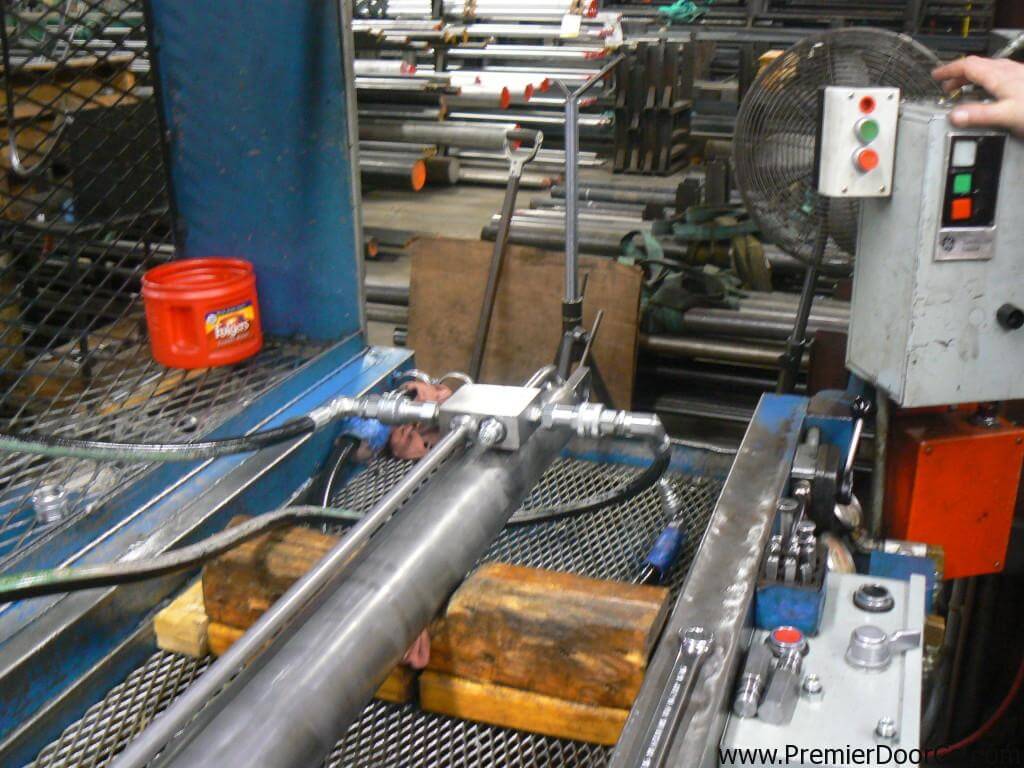
Imagine that the mast/boom on the machine in the illustration is in the raised position and the engine/hydraulic pump is disabled the pump provides the pressure and flow needed to lower the boom/mast safely.
The only way to lower the boom/mast is to remove the oil, which is trapped in the cylinder between the piston seals the safety locking valve. This leaves loosening and/or removing the valve as the only means of dissipating the unpredictable amount of stored energy from the cylinder - or to use the correct description - weight loaded accumulator!
A similar situation occurred at a mine in Globe, Arizona when a mechanic, following the advice of a factory expert, was screwing a safety valve out of its housing to lower the boom on an engine-disabled basket lift. Due to the fact that the threads restricted the leakage to a few drops per minute, the mechanic decided to, as he put it, give it another turn.
With only one or two threads left in the valve body, the pressure, and resultant force agianst the cartridge valve, sheared the threads, propelling it out unexpectedly. The ensuing jet of oil blew both the mechanic"s safety glasses and hard hat off and sent him reeling backwards to the ground. His colleagues scattered in all directions.
Figure 2Cartridge Valve Manufacturers Offer the Same Advice -While chatting with an applications engineer for one of the largest cartridge valve manufacturers in the U.S., I asked him what advice he offers personnel who are faced with the same dilemma - back the cartridge out and let the oil drip past the threads, was his rhetorical response he did admit that it was a dangerous procedure!Pressures and Flow Rates are Usually Unknown -A hydraulic cylinder, which is supporting a boom or a mast, is for all intents and purposes, a weight-loaded accumulator. The magnitude of the stored energy can be calculated by the weight (load), the area of the cylinder (s), and the cylinder rod stroke.
Lets say that the boom on a given crane weighs 4,000 lbs., and the area of the lift cylinder is 5 square inches. If the formula to calculate the pressure in the cylinder is force (weight) divided by area (piston), then the pressure is:
Lets say that the piston rod area is 2 square inches. The weight 4000 lbs divided by the area 2 square inches makes the pressure rise to an astounding 2000-PSI!Money is the Root of All Evil! -Ironically, the reason why maintenance personnel are subjected to these, and other, life-threatening hazards, is due to the fact that making a hydraulic system safe costs money, and while OSHA et al, look the other way when it comes to hydraulic safety, there is no reason to make the investment.
Another reason why aerial lift and scissor lift manufacturers get away with the safety issues is because less than 1% of the personnel who work on the hydraulic systems are properly trained untrained people will heed bad advice when it comes from the so-called experts after all, they must know what they are talking about because they designed the machine!Heed My Advice - DONT DO IT!!! -Let me make it abundantly clear removing a cartridge valve while it is under pressure could lead to severe injury, death, and/or substantial property damage. You are usually called upon to remove a cartridge valve because an engineer failed to design-in safety for a number of reasons:
Its your decision. Understand the reasons why the situation you are in has occurred in the first place, and then decide if you are willing to risk your life, and that of your colleagues, to compensate for poor engineering in concert with a blatant disregard for the safety of the people who work on and around this type of machinery.
If you are told to remove a cartridge valve plead ignorance ask for a demonstration! The only way to stop this problem in its tracks is to have the engineer, or the president of the respective company, come face-to-face with the wrath of the hot, pressurized oil.
I asked OSHA to intervene they were not interested. Remember, hydraulics is not a recognized occupational hazard. While OSHA et al, "talk the talk" about stored hydraulic energy, they dont "walk the walk" you are on your own choose wisely!
Ironically, there is a hydraulic safety product on the market that is designed specifically for the purpose of safely removing stored energy from hydraulic systems it only costs a few dollars! (www.safe-t-bleed.com)
string(741) "We understand the importance of quality brakes and supply a range with exceptional holding power for both wet and dry conditions, for a variety of applications and industries. Designed and built for the harshest conditions, our range of brakes are utilised on a arrange of equipment including loaders, cotton harvesters, oil rig equipment, cranes, serial work platforms and boom lifts. We supply multi-disc brakes and torque lock brake systems from leading manufacturers including Ausco and Fairfield. Our hydraulic brake range is currently not available to purchase through our online shop. For product information, pricing and availability regarding our hydraulic brake range please fill out a form, call or email us using the links below."
string(741) "We understand the importance of quality brakes and supply a range with exceptional holding power for both wet and dry conditions, for a variety of applications and industries. Designed and built for the harshest conditions, our range of brakes are utilised on a arrange of equipment including loaders, cotton harvesters, oil rig equipment, cranes, serial work platforms and boom lifts. We supply multi-disc brakes and torque lock brake systems from leading manufacturers including Ausco and Fairfield. Our hydraulic brake range is currently not available to purchase through our online shop. For product information, pricing and availability regarding our hydraulic brake range please fill out a form, call or email us using the links below."
string(673) "Coolers and heaters work to maintain an ideal working temperature of hydraulic fluid to prevent fluid damage or system failures. We source a range of hydraulic coolers and heaters from well-known suppliers including Olaer. Our range of Olaer coolers and heaters includes: Air/oil heat exchangers including LAC Series, LDC Series, LHC Series Water/oil heat exchangers including PWO Series Air/water coolers Our hydraulic coolers and heaters range is currently not available to purchase through our online shop. For product information, pricing and availability regarding our hydraulic coolers and heaters range please fill out a form, call or email us using the links below."
string(673) "Coolers and heaters work to maintain an ideal working temperature of hydraulic fluid to prevent fluid damage or system failures. We source a range of hydraulic coolers and heaters from well-known suppliers including Olaer. Our range of Olaer coolers and heaters includes: Air/oil heat exchangers including LAC Series, LDC Series, LHC Series Water/oil heat exchangers including PWO Series Air/water coolers Our hydraulic coolers and heaters range is currently not available to purchase through our online shop. For product information, pricing and availability regarding our hydraulic coolers and heaters range please fill out a form, call or email us using the links below."
string(884) "Hydraulic gearboxes are a reliable and effective solution for power transmission and motion control, suitable for many types of off-road, mobile vehicles and equipment. We source a complete range for light duty industrial automation applications from well-known brands such as Fairfield and Bonfigioli. Our range of Fairfield gearboxes includes: Torque-hub wheel drives Torque-hub shaft output drives Excel Series including 7000, 11000, 18000 Series Torque-hub planetary final drives including CT and CW Series Our range of Bonfiglioli gearboxes includes: Industrial gearboxes including 300 Series Multipurpose Gearbox Planetary gearboxes Our hydraulic gearbox range is currently not available to purchase through our online shop. For product information, pricing and availability regarding our hydraulic gearbox range please fill out a form, call or email us using the links below."
string(884) "Hydraulic gearboxes are a reliable and effective solution for power transmission and motion control, suitable for many types of off-road, mobile vehicles and equipment. We source a complete range for light duty industrial automation applications from well-known brands such as Fairfield and Bonfigioli. Our range of Fairfield gearboxes includes: Torque-hub wheel drives Torque-hub shaft output drives Excel Series including 7000, 11000, 18000 Series Torque-hub planetary final drives including CT and CW Series Our range of Bonfiglioli gearboxes includes: Industrial gearboxes including 300 Series Multipurpose Gearbox Planetary gearboxes Our hydraulic gearbox range is currently not available to purchase through our online shop. For product information, pricing and availability regarding our hydraulic gearbox range please fill out a form, call or email us using the links below."
string(722) "Berendsen sources a large selection of hydraulic hoses and fitting sizes such as braided, spiral and multi-purpose hydraulic hoses. These ultimate fluid conveyance solutions are equipped with wide operating pressure ranges, optimal levels of abrasion resistance, long-lasting durability and high-performance transfer capabilities. We supply hydraulic hose, fittings, adapters, couplings and fluid connectors from well-known suppliers including Eaton Aeroquip. Our hydraulic hose and fitting range is currently not available to purchase through our online shop. For product information, pricing and availability regarding our hydraulic hose and fitting range please fill out a form, call or email us using the links below."
string(722) "Berendsen sources a large selection of hydraulic hoses and fitting sizes such as braided, spiral and multi-purpose hydraulic hoses. These ultimate fluid conveyance solutions are equipped with wide operating pressure ranges, optimal levels of abrasion resistance, long-lasting durability and high-performance transfer capabilities. We supply hydraulic hose, fittings, adapters, couplings and fluid connectors from well-known suppliers including Eaton Aeroquip. Our hydraulic hose and fitting range is currently not available to purchase through our online shop. For product information, pricing and availability regarding our hydraulic hose and fitting range please fill out a form, call or email us using the links below."
string(750) "Instrumentation and gauges are essential elements of hydraulic systems and include pressure gauges, pressure switches, flow meters, pressure sensors, temperature sensors, turbine flow meters, gear flow meters, speed sensor infrareds and mini test fittings and hoses. We source a large range of instrumentations and gauges from MP Filtri, Hystar and The Hydraulic Warehouse. Our range of MP Filtri instrumentation and gauges includes: ICM particle counter LPA2 particle counter Our instrumentation and gauges range is currently not available to purchase through our online shop. For product information, pricing and availability regarding our hydraulic instrumentation and gauges range please fill out a form, call or email us using the links below."
string(750) "Instrumentation and gauges are essential elements of hydraulic systems and include pressure gauges, pressure switches, flow meters, pressure sensors, temperature sensors, turbine flow meters, gear flow meters, speed sensor infrareds and mini test fittings and hoses. We source a large range of instrumentations and gauges from MP Filtri, Hystar and The Hydraulic Warehouse. Our range of MP Filtri instrumentation and gauges includes: ICM particle counter LPA2 particle counter Our instrumentation and gauges range is currently not available to purchase through our online shop. For product information, pricing and availability regarding our hydraulic instrumentation and gauges range please fill out a form, call or email us using the links below."
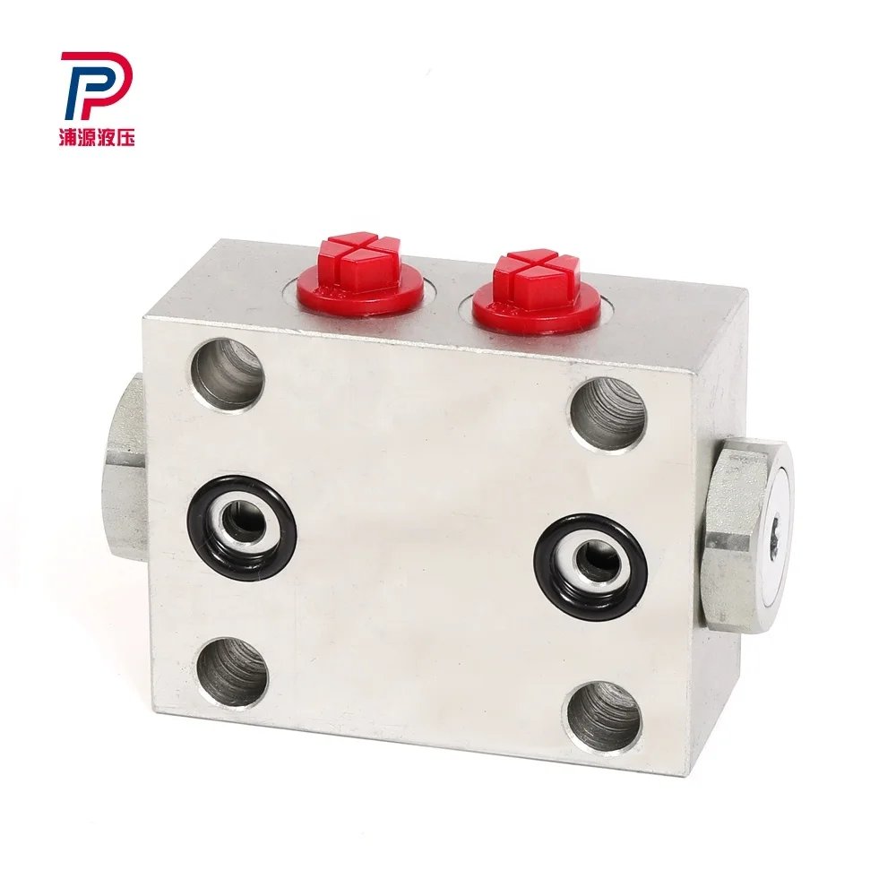
string(1167) "Manifolds regulate the fluid flow between pumps, actuators and other components in a hydraulic system, allowing the operator to control how much fluid flows between the different components. Berendsen is proud to have developed our own range of standard manifolds and custom designed and manufactured manifolds to meet the needs of a range of industrial applications. Our standard range of manifolds includes station manifolds, CETOP 3 manifolds, CETOP 5 manifolds and sub-plates. Custom Designed and Manufactured Manifolds Manufactured to the highest quality at our ISO certified manufacturing hub in Newcastle, our range includes steel, aluminium and stainless steel manifolds. Our world class CAD manifold design software and the latest technologies applied in our manufacturing process make us the first choice supplier of custom and standard manifolds. Click here for more information on our custom manifold manufacturing capabilities. Our manifold range is currently not available to purchase through our online shop. For product information, pricing and availability regarding our manifold range please fill out a form, call or email us using the links below."
string(1167) "Manifolds regulate the fluid flow between pumps, actuators and other components in a hydraulic system, allowing the operator to control how much fluid flows between the different components. Berendsen is proud to have developed our own range of standard manifolds and custom designed and manufactured manifolds to meet the needs of a range of industrial applications. Our standard range of manifolds includes station manifolds, CETOP 3 manifolds, CETOP 5 manifolds and sub-plates. Custom Designed and Manufactured Manifolds Manufactured to the highest quality at our ISO certified manufacturing hub in Newcastle, our range includes steel, aluminium and stainless steel manifolds. Our world class CAD manifold design software and the latest technologies applied in our manufacturing process make us the first choice supplier of custom and standard manifolds. Click here for more information on our custom manifold manufacturing capabilities. Our manifold range is currently not available to purchase through our online shop. For product information, pricing and availability regarding our manifold range please fill out a form, call or email us using the links below."
string(580) "Berendsen source pneumatic filters, valves and cylinders to assist in compressed air applications. These products are available to suit a variety of applications and are guaranteed to fit your system requirements. Our range of pneumatic filters, valves and cylinders are sourced from well-known brands including Norgren, SMC and Parker. Our pneumatic product range is currently not available to purchase through our online shop. For product information, pricing and availability regarding our pneumatic product range please fill out a form, call or email us using the links below."
string(580) "Berendsen source pneumatic filters, valves and cylinders to assist in compressed air applications. These products are available to suit a variety of applications and are guaranteed to fit your system requirements. Our range of pneumatic fi


 8613371530291