
hydraulic cylinder safety valve factory
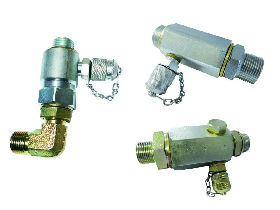
Hydraulic relief valves are used to limit the pressure in a hydraulic system. They achieve this result by allowing the pressurized hydraulic fluid to flow out of the system into an auxiliary passage.
In hydraulic control systems, the relief valve acts as a check valve, with a ball and an adjustable spring. When a relief valve opens to divert fluid into an auxiliary passage, the pressure inside the hydraulic cylinder drops and allows the valve to close. A hydraulic system will often employ several types of valves, although the hydraulic relief valve is usually the first encountered in the circuit. Hydraulic relief valves can be found in almost any mechanism that runs on hydraulic power, such as automobile transmissions, brakes, power steering, aviation and in industrial and construction machinery.
Relief valves are built from the same basic materials that most hydraulic valves are made from. The strong and corrosion resistant metals that are most common are stainless steel, aluminum, iron, brass and copper. Aluminum and stainless steel are thin, lightweight and flexible, while still retaining the strength necessary to control the flow of liquid. Usually when a heavy metal like iron is used for the body of a valve, one of those two lighter metals is still used for the disc or plunger. Plastic is also used, particularly thermoplastics that are developed specifically to be used as valve material. Although they are not as resistant to corrosion as metal, they are cheaper. It’s all about options.
Hydraulic relief valves protect hydraulic systems from being exposed to high pressures that exceed the mechanism"s specified limits. A relief valve is placed at the entrance to a separate tube and is set to only open when a certain amount of pressure is applied, which can only be applied if there is too much liquid or gas in the chamber or pipe. An auxiliary passage, which is where the relief valve sends the extra liquid or gas to relieve the pressure in a mechanism, is usually just an extra pipe that leads to a chamber where most likely the fluid is burned and the gas left over is released into the atmosphere.
This is a particular necessity in the chemical and petrochemical manufacturing industry, as well as in petroleum refining plants, natural gas processing and power generation industries. If the pressure in a hydraulic pump exceeds its designed pressure limit, internal leakage or damage to the pump components can occur. Depending on what the liquid is, such leaks could also cause serious damage to individuals in the vicinity and the environment.
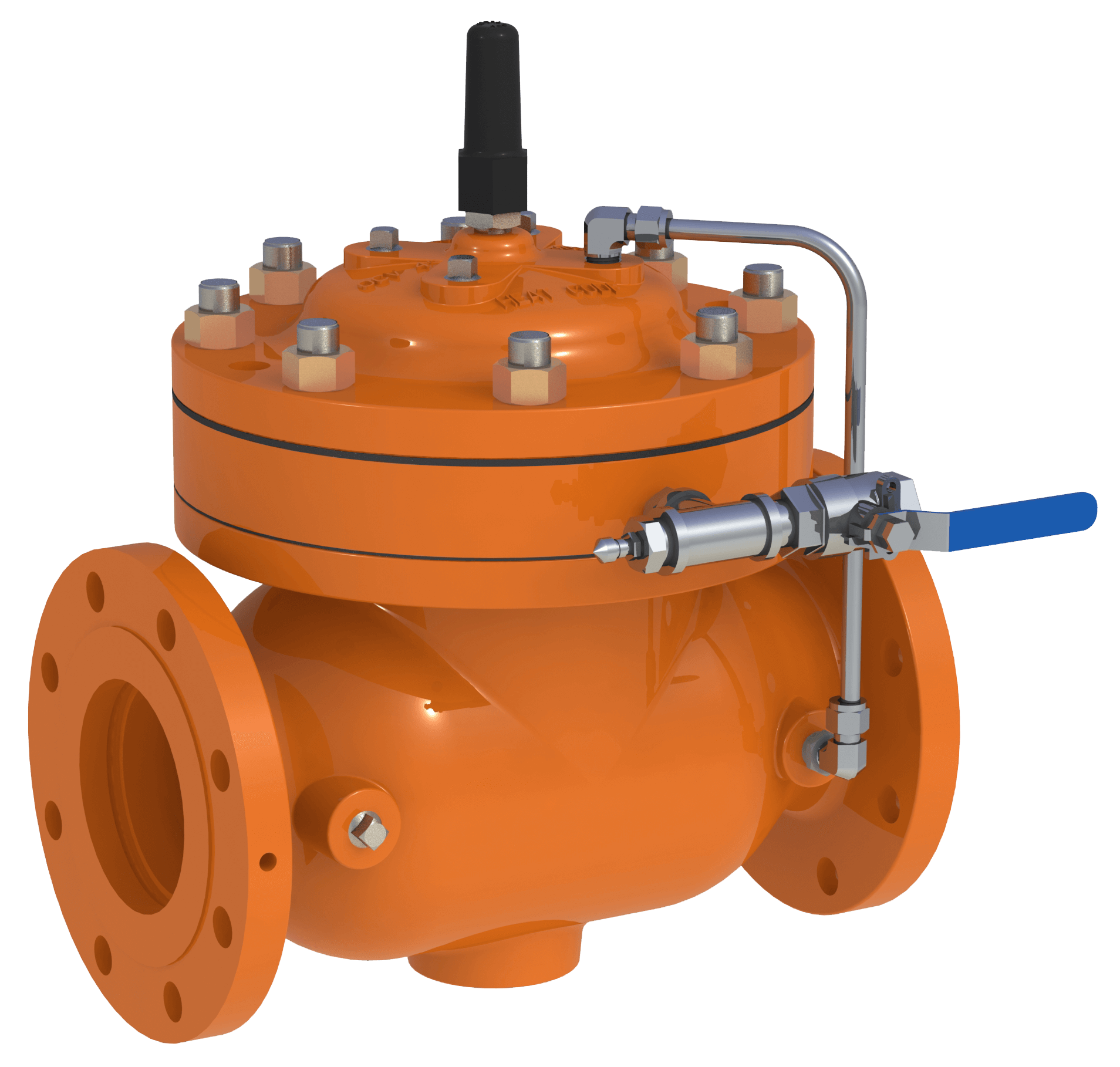
The S50 Safety Shut Off valve is mainly used to avoid any damage to components as well as to avoid too high or too low pressure in the gas train. This could cause high financial losses and/or injured ...
Excavator pipe-rupture valves prevent uncontrolled cylinder movement in the event that a pipe or hose bursts. The ESV valve fulfills all of the requirements of the ISO 8643 and EN 474-5 ...
... base of an hydraulic cylinder, while the hose can be applied on the valve without any other components needed. The safety valves VUBA-DIN avoid an uncontrolled lowering ...
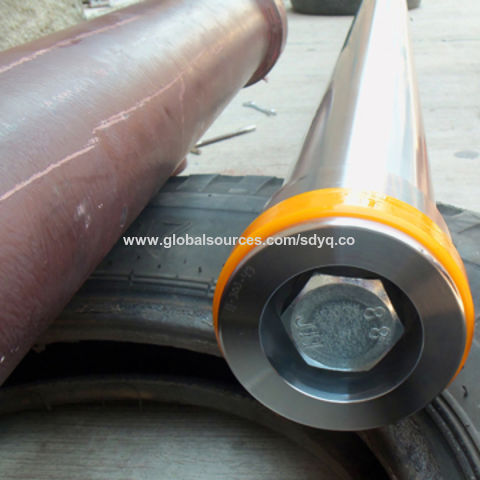
Hydraulic safety valves are made according to API 6A. When oil and gas leaking or firing, used for security protect on well site, the control system includes low pressure ...
Jereh Safety Valve is equipped with pneumatic, hydraulic or electric actuator, widely used in Christmas tree and surface manifold. In case of any emergency ...
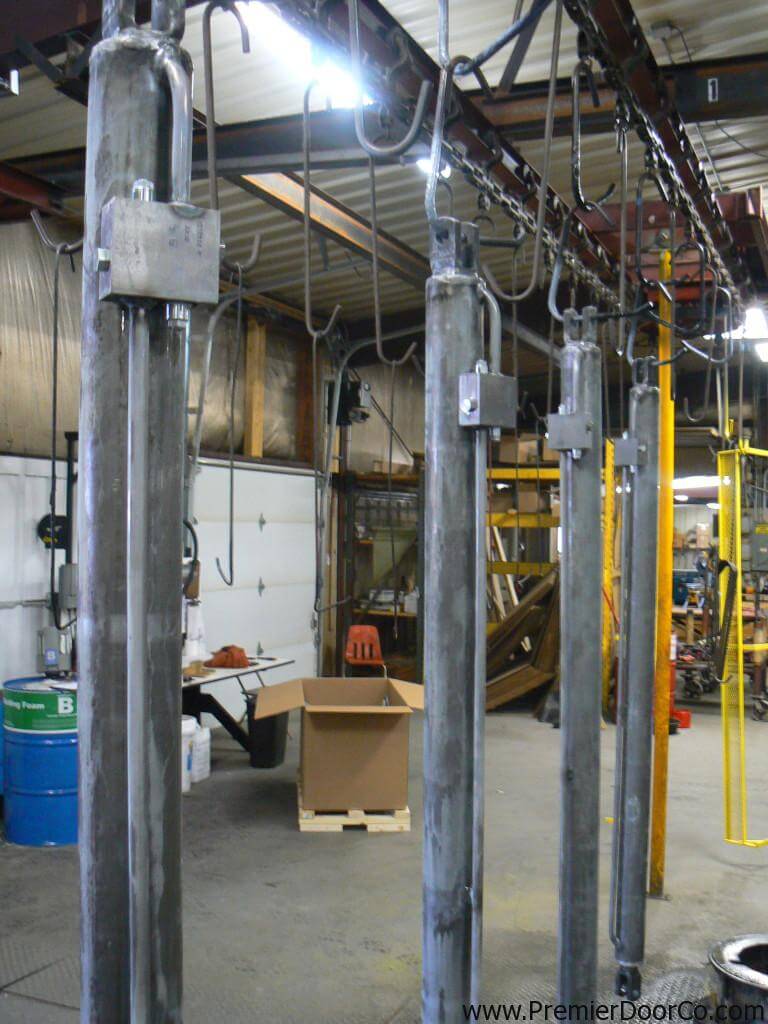
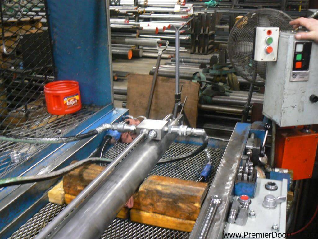
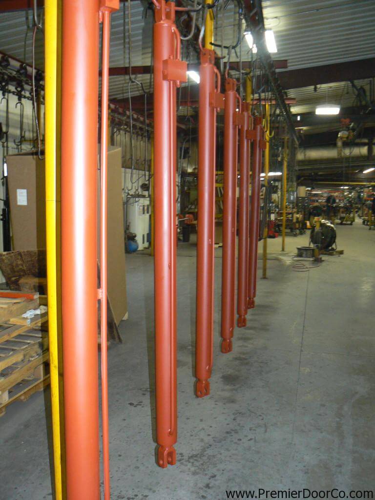
Our Industrial style cylinders are sized appropriately per door width and height. Featuring long stroke and extended mounting centers to cover the span of the door for rigid integrity. Our cylinders are custom made in small batches with high quality materials. Many hydraulic cylinders look alike. However its whats inside that counts.
An auxiliary passage, which is where the relief valve sends the extra liquid or gas to relive the pressure in a mechanism, is usually just an extra pipe that leads to a chamber where most likely the fluid is burned and the gas left over is released into the atmosphere. This is a particular necessity in the chemical and petrochemical manufacturing industry, as well as in petroleum refining plants, natural gas processing and power generation industries.
If the pressure in a hydraulic pump exceeds its designed pressure limit, internal leakage or damage to the pump components can occur. Depending on what the liquid is, such leaks could also cause serious damage to individuals in the vicinity and the environment.
In hydraulic control systems, the relief valve acts as a check valve, with a ball and an adjustable spring. When a relief valve opens to divert fluid into an auxiliary passage, the pressure inside the hydraulic cylinder drops and allows the valve to close. A hydraulic system will often employ several types of valves, although the hydraulic relief valve is usually the first encountered in the circuit.
Hydraulic relief valves can be found in almost any mechanism that runs on hydraulic power, such as automobile transmissions, brakes, power steering, aviation and in industrial and construction machinery. Relief valves are built from the same basic materials that most hydraulic valves are made from. The strong and corrosion resistant metals that are most common are stainless steel, aluminum, iron, brass and copper.
Aluminum and stainless steel are thin, light weight and flexible, while still retaining the strength necessary to control the flow of liquid. Usually when a heavy metal like iron is used for the body of a valve, one of those two lighter metals is still used for the disc or plunger.
Plastic is also used, particularly thermoplastics that are developed specifically to be used as valve material. Although they are not as resistant to corrosion as metal, they are cheaper. It"s all about options.

When your application requires counterbalance or pilot-operated check valves, the ideal location is directly mounted to the cylinder because it continues to provide load holding protection even when a hose fails. From basic single or dual counterbalance valves to complex integrated circuits, our team will design your cylinders with compact valve manifolds. You can also use our online cylinder calculator to generate a quote based on your specifications.
This invention relates generally to a safety valve for use in a hydraulic line system which prevents flow of a working hydraulic fluid above a specific flow rate and more particularly to a safety valve which is located in the barrel of a chute lift cylinder of a ready mix concrete truck.
The delivery chute on the rear of ready mix concrete trucks is conventionally raised and lowered by means of a hydraulic cylinder. In normal operating use, the chute is often full of concrete and held in position by a hydraulic cylinder. The hydraulic hose connected to the hydraulic cylinder is subject to wear, damage, and deterioration by the nature of its application. Frequent inspections for cuts, abrasions, wear, acid wash damage, etc., are necessary to prevent hose failure during operation. Failure may occur if the hose is not regularly inspected. Failure also results from damage occurring on the job site. Workers tugging and pulling on a heavy, full concrete chute can cause pressure spikes in the hydraulic fluid flowing through the chute lift hydraulic hose. Workers can also use the hydraulic hose connection to the cylinder as a hand hold which causes further damage and wear to the hose and connection. Previously damaged hoses may break from the pressure spikes in the chute lift hydraulic hose. A broken hose results in a sudden pressure loss and the fluid flow is no longer controlled. The sudden loss of pressure results in hydraulic fluid rapidly flowing from the hydraulic cylinder, resulting in the chute crashing downward and potentially seriously injuring workers.
The present invention is a safety valve which prevents the chute from rapidly falling due to a sudden loss of hydraulic fluid pressure. The safety valve is located in the interior of the chute lift hydraulic cylinder. The cylinder mount is drilled and tapped to provide for the safety valve located in the cylinder"s barrel and the cylinder"s port located in the cylinder mount. Normal hydraulic fluid flow coming out of the chute lift cylinder is less than three gallons per minute. The gallons per minute flow increases dramatically should the hydraulic hose break. The safety valve is activated any time the flow leaving the chute lift cylinder exceeds a predetermined value, e.g., approximately four gallons per minute. The safety valve immediately blocks further hydraulic fluid from leaving the chute lift cylinder and, thus, the chute cannot fall.
The principle object of this invention is to provide an internal safety valve to prevent the rapid falling of a hydraulically held concrete chute due to sudden loss of hydraulic pressure because of a hydraulic line failure.
FIG. 2 is a view of a retracted hydraulic cylinder partially cut away to show the location of the safety valve in the barrel of the hydraulic cylinder;
FIG. 3 is a view of an extended hydraulic cylinder partially cut away to show the location of the safety valve in the barrel of the hydraulic cylinder;
As shown in FIG. 1, a work type vehicle, namely a ready mix concrete truck, is indicated generally by 10. It includes a rotatable mixer drum 12. Cement or concrete is emptied through discharge spout 13 into a discharge chute 15. This discharge chute 15 is used to cause the concrete to flow into a bucket, wheel barrel or to a space defined by erected concrete forms. Discharge chute 15 is positioned by means of the chute lift hydraulic cylinder 20. Workers also pull and tug on the chute for lateral positioning thereof.
The present invention relates to a hydraulic cylinder safety valve assembly designated generally as 21, consisting of a safety valve device 25 located within the discharge chute cylinder 20. A hydraulic hose 28 is connected to the inport valve 30 of the discharge chute cylinder 20. The discharge chute cylinder used typically is a displacement single action hydraulic cylinder. Controlled flow of the hydraulic fluid is from the hydraulic hose 28 into the cylinder 20 when the cylinder is extended and from the cylinder 20 to the hydraulic hose when the cylinder is retracted. The cylinder 20 consists of a barrel 32, piston 34, cylinder mount 36 and a moving seal 38. The cylinder mount is drilled and tapped for the intake valve 30 and the safety valve 25. A bore 40 connects intake valve 38 with a longitudinal bore 41 of the safety valve device 25. The safety valve 25 is located within bore 31 of the cylinder barrel 32 adjacent the cylinder mount 36. The piston 34 is mounted for reciprocation within the barrel 32. When the piston 34 is in the extended position the cement chute is raised as shown by the solid lines in FIG. 1. When the piston 34 is in the retracted position as shown in FIG. 3 and by the broken lines of FIG. 1, the cement chute 15 is lowered. The piston 34 has an internal cavity 35 which receives the safety valve 25 when in the retracted position shown in FIG. 3.
The safety valve 25 is shown in FIGS. 2, 3, 4 and 5. The safety valve 25 is threaded onto the cylinder mount 36. The valve 25 contains a longitudinal bore 41 and counter bore 42. The counter bore 42 contains a moveable cylindrical spool 44, compression spring 46, and a poppet 48 which will be described in further detail below. The poppet valve seat 48 is located in the counter bore 42 and has a radial flange 50 and base 52 containing opening 54. The flange 50 is located at the end of the valve 25 adjacent the cylinder mount 36 and longitudinal bore 41. The poppet 48 has a main cylindrical body 56 containing a bore 58. The main cylindrical body 56 tapers to a section containing two opposed ports. These two ports 60 and 62 provide for fluid communication between the poppet bore 58 and the valve interior 42. The poppet 48 then tapers into a conical end 64.
The spool 44 is located within counter bore 42. The spool spring 46 is also located within bore 42 and extends into the spool interior 66. A portion of spool spring 46 surrounds the poppet 48. FIG. 4 shows the spring during controlled flow. Spool spring 46 provides the biasing means to urge spool 44 away from the poppet 48, creating a fluid passage way through the ports 60 and 62 into the spool interior 66 and through the spool aperture into the cylinder barrel. The valve operates to restrict flow when the fluid pressure on the spool surrounding the aperture increases compressing spool spring 46 forcing the spool aperture 68 against the conical end 64 of the poppet 48. This is the closed position shown in FIG. 5. The aperture 68 of the spool 44 is of a diameter greatly smaller than the diameter of the spool and the counter bore 42. This aperture may, for example, be 0.125".
The arrows in the FIGS. 2 and 3 show the flow of fluid from the cylinder through the valve during extension and retraction of the cylinder. In FIGS. 2 and 4, hydraulic fluid flows from the cylinder port fluid inlet valve 30 into the cylinder mount bore 40 and then into the flow valve inlet 41. From the inlet 41, fluid passes into the poppet bore 58 and out of the ports 60 and 62. The flow then enters the interior 66 of the spool 48 where it passes through the spool aperture 68 into the counter bore 42 and finally through flow valve port 49 into the cylinder barrel. The introduction of fluid into the hydraulic cylinder barrel 32 and bore 35 causes the piston 34 to extend from the cylinder barrel 32. When it is desired to retract the piston 34 to lower the cement chute 15, the hydraulic fluid is released from the hydraulic piston 34 and flows in the opposite direction through the valve 25.
Fluid will readily pass in either direction when the flow rate in the valve 25 is less than a predetermined rate, e.g., approximately four gallons per minute. The flow rate less than the predetermined rate is the controlled rate of the hydraulic system. The spring 46 has sufficient stiffness such that the fluid pressure on the spool surface as fluid enters the spool aperture 68 is insufficient to cause the spool 44 to move against the force of the spring 46. When the flow rate into the valve 25 from the cylinder 20 exceeds approximately four gallons per minute, the fluid pressure on the spool 44 surface will increase as the fluid rushes to enter the spool aperture 68. The increased fluid pressure on the spool 44 surface causes the spool 44 to move against the force of the spring 46 towards the poppet 48. The spool 44 moves until the aperture 68 engages the conical end 64 of the poppet 48. The spool aperture 68 is blocked thereby restricting fluid flow.
In the event the hydraulic hose breaks, the fluid pressure decreases rapidly on the system port end. Hydraulic fluid leaves the cylinder 20 at an increased flow rate to compensate for the sudden pressure decrease. Accordingly, fluid pressure increases against the spool 44 surface as the hydraulic fluid rushes to enter the spool aperture 68 at an increased flow rate. When the flow rate exceeds the predetermined flow rate, the spool 44 moves against the force of the spring 46 towards the poppet 48. The flow is restricted as the conical end 64 of the poppet engages the spool aperture 68. Hydraulic fluid can no longer flow through the safety valve. Consequently, the hydraulic fluid remains in the hydraulic cylinder maintaining the position of the concrete discharge chute.

While conducting a hydraulic safety workshop for one of the largest equipment rental companies in the US recently, I was told, by a student, that a representative of an aerial lift manufacturer advised him to remove a cartridge valve from the base of a boom lift cylinder to relieve pressure from a boom cylinder after the engine failed.
In this instance, an aerial lift platform apparently tipped over. As it lay on its side, engine oil found its way into the engine cylinders. When righted, an attempt to start the engine proved fruitless because the engine had hydro-locked leaving the maintenance personnel wondering how to lower the boom.
Upon discussing the matter with the manufacturers technical experts, he was told to carefully screw the safety valve out until it was free of the o-ring seal, which would allow the oil to leak out past the threads thus allowing the boom to lower very slowly.
Imagine that the mast/boom on the machine in the illustration is in the raised position and the engine/hydraulic pump is disabled the pump provides the pressure and flow needed to lower the boom/mast safely.
The only way to lower the boom/mast is to remove the oil, which is trapped in the cylinder between the piston seals the safety locking valve. This leaves loosening and/or removing the valve as the only means of dissipating the unpredictable amount of stored energy from the cylinder - or to use the correct description - weight loaded accumulator!
A similar situation occurred at a mine in Globe, Arizona when a mechanic, following the advice of a factory expert, was screwing a safety valve out of its housing to lower the boom on an engine-disabled basket lift. Due to the fact that the threads restricted the leakage to a few drops per minute, the mechanic decided to, as he put it, give it another turn.
With only one or two threads left in the valve body, the pressure, and resultant force agianst the cartridge valve, sheared the threads, propelling it out unexpectedly. The ensuing jet of oil blew both the mechanic"s safety glasses and hard hat off and sent him reeling backwards to the ground. His colleagues scattered in all directions.
Figure 2Cartridge Valve Manufacturers Offer the Same Advice -While chatting with an applications engineer for one of the largest cartridge valve manufacturers in the U.S., I asked him what advice he offers personnel who are faced with the same dilemma - back the cartridge out and let the oil drip past the threads, was his rhetorical response he did admit that it was a dangerous procedure!Pressures and Flow Rates are Usually Unknown -A hydraulic cylinder, which is supporting a boom or a mast, is for all intents and purposes, a weight-loaded accumulator. The magnitude of the stored energy can be calculated by the weight (load), the area of the cylinder (s), and the cylinder rod stroke.
Lets say that the boom on a given crane weighs 4,000 lbs., and the area of the lift cylinder is 5 square inches. If the formula to calculate the pressure in the cylinder is force (weight) divided by area (piston), then the pressure is:
Lets say that the piston rod area is 2 square inches. The weight 4000 lbs divided by the area 2 square inches makes the pressure rise to an astounding 2000-PSI!Money is the Root of All Evil! -Ironically, the reason why maintenance personnel are subjected to these, and other, life-threatening hazards, is due to the fact that making a hydraulic system safe costs money, and while OSHA et al, look the other way when it comes to hydraulic safety, there is no reason to make the investment.
Another reason why aerial lift and scissor lift manufacturers get away with the safety issues is because less than 1% of the personnel who work on the hydraulic systems are properly trained untrained people will heed bad advice when it comes from the so-called experts after all, they must know what they are talking about because they designed the machine!Heed My Advice - DONT DO IT!!! -Let me make it abundantly clear removing a cartridge valve while it is under pressure could lead to severe injury, death, and/or substantial property damage. You are usually called upon to remove a cartridge valve because an engineer failed to design-in safety for a number of reasons:
Its your decision. Understand the reasons why the situation you are in has occurred in the first place, and then decide if you are willing to risk your life, and that of your colleagues, to compensate for poor engineering in concert with a blatant disregard for the safety of the people who work on and around this type of machinery.
If you are told to remove a cartridge valve plead ignorance ask for a demonstration! The only way to stop this problem in its tracks is to have the engineer, or the president of the respective company, come face-to-face with the wrath of the hot, pressurized oil.
I asked OSHA to intervene they were not interested. Remember, hydraulics is not a recognized occupational hazard. While OSHA et al, "talk the talk" about stored hydraulic energy, they dont "walk the walk" you are on your own choose wisely!
Ironically, there is a hydraulic safety product on the market that is designed specifically for the purpose of safely removing stored energy from hydraulic systems it only costs a few dollars! (www.safe-t-bleed.com)

Metro’s lock valves, is a pilot operated check valve, is designed to lock a hydraulic cylinder and prevent them from drifting due to hydraulic leak from a directional control valve being in the neutral position or worn hydraulic valves or even a hose failure.
The Cross series relief valves have been designed to give long life and smooth performance at an economical price. The hydraulically dampened poppet uses differential areas to provide minimal variations between opening and full flow pressures.

Leak-free load-control valves (CINDY) take over the precision control operations, the leak-free load holding in the rest position, and the safety functions. They prevent hydraulic actuators from running ahead of the available oil supply when they are acted on by an external driving load. Thanks to the particular design of the main control axis, these load-control valves offer extremely low leakage rates. Leak-free load-control valves in this series are also ideally suited for use in high-pressure applications up to 420 bar (6000 psi). Thanks to a variety of optional components, the series can be extended and adapted to the requirements of the system.
Load holding – When a hydraulic cylinder is required to hold its position for an extended period without drifting, load holding valves are the answer. Think a mobile crane outrigger that needs to maintain a level position or a manlift that is extended for work on utility lines.
Pressure relief – In certain situations, such as a significant temperature swing, load holding valves can provide pressure relief to avoid pressure intensification and system failure.
Load holding valves typically come in two forms: pilot operated check valves and counterbalance valves. Both valves lock the fluid in a cylinder to prevent drifting, but there are some key differences between the two.
Pilot-operated check valves, also known as pilot-to-open check valves, are non-modulating valves that are considered in operation to be either fully open or fully closed. They allow hydraulic fluid to flow into a cylinder but restrict flow out of the cylinder unless pressurized fluid is supplied through a pilot line.
P.O. check valves work well in load or position holding applications due to their typically near-zero leakage. They also prevent cylinder drift due to a slow leak or rapid motion due to a ruptured hydraulic hose. They can literally be a lifesaver.
But unlike their cousin, the counterbalance valve, a PO check valve is not capable of metering the oil flow through them and therefore do not function well with over-running loads. When lowering a load being acted on by gravity, a P.O. check valve may cause severe ratcheting of the cylinder and resultant shock in the hydraulic system.
A counterbalance valve is a modulating valve that not only acts as a load holding brake but is also able to maintain control over a load in motion. This is especially important in mobile applications, where an “over-center” load can make a cylinder over-speed the pump. The load tries to move quicker than the desired flow rate.
A counterbalance valve will only open enough to allow a load to move at a desired flow rate ensuring the load will not “run away” due to external forces, such as gravity. So, unlike a P.O check valve, a counterbalance valve can provide full flow for hoisting while metering flow to provide controlled lowering.
Another key difference and advantage to a counterbalance valve is its relief characteristic. In cylinders with high bore / rod ratios thermal expansion on the cap end can cause pressure on the annular side to rise beyond yield strength of the material which results in an intensification failure. This may materialize as a ballooned barrel, a collapsed rod, a blown-out gland or seal – or a combination of failures.
If the cylinder is designed with a counterbalance valve on both the extend and retract side, the retract counterbalance will open once pressure reaches the valve setting and allow the pressure to be relieved through the control valve. If the cylinder is designed with a pilot to open check valve, the pressure cannot be relieved, as there is no relief characteristic to the valve. The pressure will rise until material yield or seal failure occurs.
In applications where there are large swings in ambient temperature, such as desert locations, thermal expansion can cause cylinders equipped with pilot operated check valves to lock in position – even when commanded to move.
An external manifold has the benefit of easy replacement should something fail, as it is located outside of the cylinder. A load holding valve manifold can also be added to an existing hydraulic system quite easily if there is ample room for it. The main disadvantage here is that the external valve manifold is mounted externally and therefore can be subject to impact and the elements.
Direct integration allows the valves to be designed and housed right into the cylinder. The greatest benefit here is the reduced risk of external leakage or hose failure. There is flexibility in valve location to integrate with equipment and added protection from external hazards. However, integrating valves directly into a cylinder requires 2-3” of space which must be factored into the overall length and cylinder stroke. This is an easy task when designing a cylinder from scratch but can pose a challenge when integrating into an already-fabricated cylinder.
In load holding applications a P.O. check valve can be a suitable and a more economical choice. In applications that also require controlled lowering or the benefit of pressure relief, a counterbalance valve is the only solution and worth the extra cost.
There are many options when selecting load holding valves for your application. From basic single or dual valve design to complex circuits, we can provide a cost-effective solution for all applications and working pressures.


 8613371530291