
hydraulic cylinder safety valve manufacturer

An auxiliary passage, which is where the relief valve sends the extra liquid or gas to relive the pressure in a mechanism, is usually just an extra pipe that leads to a chamber where most likely the fluid is burned and the gas left over is released into the atmosphere. This is a particular necessity in the chemical and petrochemical manufacturing industry, as well as in petroleum refining plants, natural gas processing and power generation industries.
If the pressure in a hydraulic pump exceeds its designed pressure limit, internal leakage or damage to the pump components can occur. Depending on what the liquid is, such leaks could also cause serious damage to individuals in the vicinity and the environment.
In hydraulic control systems, the relief valve acts as a check valve, with a ball and an adjustable spring. When a relief valve opens to divert fluid into an auxiliary passage, the pressure inside the hydraulic cylinder drops and allows the valve to close. A hydraulic system will often employ several types of valves, although the hydraulic relief valve is usually the first encountered in the circuit.
Hydraulic relief valves can be found in almost any mechanism that runs on hydraulic power, such as automobile transmissions, brakes, power steering, aviation and in industrial and construction machinery. Relief valves are built from the same basic materials that most hydraulic valves are made from. The strong and corrosion resistant metals that are most common are stainless steel, aluminum, iron, brass and copper.
Aluminum and stainless steel are thin, light weight and flexible, while still retaining the strength necessary to control the flow of liquid. Usually when a heavy metal like iron is used for the body of a valve, one of those two lighter metals is still used for the disc or plunger.
Plastic is also used, particularly thermoplastics that are developed specifically to be used as valve material. Although they are not as resistant to corrosion as metal, they are cheaper. It"s all about options.
Valves are used to continue and discontinue flows, modify flow rates, reroute the direction of a flow, and regulate or relieve pressure (among similar purposes). Due to the wide variety of valve types, several different methods of classifying valves exist. It should be noted that the term hydraulic valve specifically refers to the application of a specific type of valve. In other words, a hydraulic valve is simply any type of valve that acts on hydraulic fluid
Hydraulic systems have existed in some way or another since the sixth century BC, when the Mesopotamians and Egyptians used water power for irrigation. Use of hydraulics was also seen in the Hellenistic age and in ancient Persia, China, Sri Lanka, and Rome. The modern age of hydraulics began in the early 1600s, with the innovations of scientists like Benedetto Castelli and Blaise Pascal. Pascal, in particular, played a pioneering role in the field of modern hydraulics.
Pascal’s law summarizes the basis upon which the principles of hydraulics are founded. In essence, this law states that when pressure is placed on any point of a confined liquid, such pressure will transmit equally to all other parts of the confined liquid. Correspondingly, if pressure increases at any point in a confined liquid, equal and proportional increases will appear at all other points in the confined liquid. It is important to note that Pascal’s Law is made possible by the fact that liquid is incompressible. It is equally important to note that is does not apply to liquids which are not confined in some type of enclosed area. Using this principle, engineers and scientists have successfully designed systems that generate, control, and transfer power via pressurized fluids, eliminating much need for manual human effort. (Fuller explanations of Pascal’s Law can be found at treatments of other hydraulic parts, including our sites on hydraulic pumps and hydraulic cylinders).
Most hydraulic valves minimally consist of a main casing, a bonnet, a seat, and a disc. The main casing is the valve’s outer enclosure; it contains all the internal components, which are collectively called the trim. Most often, the casing is made from a metallic or plastic material. Common metallic materials include steel, stainless steel, alloyed steel, cast iron, bronze, brass, and gunmetal (red brass), while among the most common plastic options are PVC, PVDF, PP, and glass-reinforced nylon.
The bonnet is a semi-permanent, removable part of the valve that acts as a cover. For access to interior parts of the valve, the bonnet needs to be removed. Some valves do not have a bonnet because of the way they are constructed. (One example of such a valve is a plug valve.)
Hydraulic valves can only be properly understood within the context of entire hydraulic systems. An entire unit that generates power hydraulically is known as a hydraulic power pack or a hydraulic power unit. Such packs or units typically consist of a reservoir, a pump, hydraulic valves, and hydraulic actuators such as motors or cylinders.
The purpose of hydraulic valves within a hydraulic power pack is to connect the power source (i.e., the pump) to the actuators which translate hydraulic power into mechanical motion (i.e. hydraulic cylinders, hydraulic motors). Through its valves, a hydraulic power system can supply its actuators with hydraulic fluid and modify the flow of such fluid as needed.
While functional, valves generally have at least two settings: open and closed. Generally speaking, fluid may flow freely through the valve if it is open. Conversely, fluid flow is restricted if the valve is closed. Valves with a default status of open are also known as open center valves, while valves with a default status of closed are known as closed center valves.
Valves are either open or closed based on the positioning of their interior pieces; more specifically, a valve’s status depends on whether or not the disc is inside the seat. Hydraulic valves (and especially ones used for directional control) are often referred to as spool valves since they visually resemble spools of thread (by containing interior trim within exterior housing). The flow of hydraulic fluid (or lack thereof) is dependent on the position of the interior “spool” portion of the valve within the exterior housing. The default or “neutral” position of many valves has the spool in a central position which blocks the flow of hydraulic fluid. In order to open the valve and let fluid through, the spool simply slides to one side of the housing and away from the neutral position. Nowadays, many hydraulic valves also allow for partial flow obstruction.
As alluded to in the introduction, hydraulic valves can be categorized in several different ways. Some methods of categorization emphasize a valve’s physical characteristics or construction. Other methods emphasize a valve’s method of actuation or control. Still other categorization methods classify hydraulic valves according to their specific application or function.
A common way to label hydraulic valves is by its number of ports. The term port simply refers to an avenue that hydraulic fluid can use to flow into or out of a valve. Standard hydraulic valves are double port, since they possess both an inlet port (to draw in fluid from the pump) and an outlet port (to pass fluid on to the actuators). However, hydraulic valves can also be three-port, four-port, or multi-port. Hydraulic manifolds are another type of valve which is classified primarily on the basis of physical characteristics. Such mechanisms are actually separate hydraulic valves that are connected to one another within hydraulic systems.
Hydraulic cartridge valves (also known as slip in valves, logic valves, or 2/2-way valves) are some of the more popular valves which derive their classification from their configuration. These valves are screwed into a threaded cavity and are typically composed of only a sleeve, a cone or poppet, and a spring. They open when incoming fluid pushes the holding cone or poppet (held in place by the spring) aside. The ease of installing cartridge valves makes them very popular in the hydraulic world.
Overall, hydraulic valves vary widely in physical shape and size. They can range in size from less than an inch to a foot long. On average, they can fit in the palm of a hand. The broad physical variety that characterizes hydraulic valves directly affects their differing uses.
It is important to note that valves can only function properly with some type of valve actuator. While not strictly a part of the valve itself, valve actuators are important since they are responsible for actually moving the machinery within a valve to change its status. Valve actuators can be either manual or automatic.
An example of a manually operated valve is the hydraulic ball valve. This valve derives its name from a spherical, internal disk containing a hole and is activated with a handle that can be quickly rotated 90° between opened and closed positions. When the valve is open, the hole in the ball disk lines up with the direction of fluid flow and allows fluid to pass through. When the valve is closed, the hole is not lined up with the fluid flow, thus blocking the flow of fluid.
Valve balls are perforated and most often made of nickel, brass, stainless steel, or titanium. (Sometimes, they are composed of a plastic, like PVC, PP, ABS, or PVDF.)
Many manually operated hydraulic valves typically require high amounts of force in order to successfully stop high-pressure flows of hydraulic fluid. Thus, many manual hydraulic valves other than ball valves are operated by oversized wheels, levers, and even hydraulic rams.
Other hydraulic valves are electrically operated, and/or guided remotely with computer controls. Hydraulic solenoid valves are an excellent example of such valves. They open and close based on the charge of a magnetic field that pushes on a plunger. The magnetic field is signaled by a current, which is received by a wire coil when the solenoid converts electrical energy into mechanical energy. Other types of electronically or remotely controlled hydraulic valves can be found in places such as construction sites, where they are critical to the operation of many hydraulically-powered construction machines.
Overall, mechanical valves in general are often classified by the exact function they are designed to exact on a fluid (e.g. completely cutting off a flow, preventing backflow, etc.). Since hydraulic valves are essentially general types of valves expressly applied in hydraulic scenarios, hydraulic valves are often also classified according to their exact regulatory function.
Control valves are valves specifically designed to control or modify the amount and speed of a fluid flow. These types of valves are particularly capable of occupying a spectrum of positions between fully open and fully closed. They are sometimes further classified as pressure control valves and flow control valves. (Control valves contrast with simple on/off valves or shutoff valves, which are designed to completely stop or start a fluid flow rather than simply modifying it.)
Directional control valves (or simply directional valves) may arguably be the “basic” type of mechanical valve, since their purpose is to control or modify the direction (rather than the amount) of fluid flow. On average, many standard hydraulic “spool” valves are used expressly for directional control and occupy a few discrete positions. Check valves (or non-return valves) are specific types of directional control valves that are used to force fluid flow in one direction only; if fluid within a hydraulic system somehow begins flowing in an undesirable direction, the check valve will close and block the flow. Check valves are critical to hydraulic systems in environments where substances of varying compositions and pressures must be kept separated (such as wastewater management plants).
Proportional valves can be considered as “extensions” of directional control valves. In addition to modifying flow direction, these type of valves can occupy intermediate positions and carry an output flow that is unequal to the input flow. In other words, proportional valves are designed to control the speed as well as the direction of fluid flow. (From this perspective, they can also be considered as extensions of control valves, which are designed to control the speed and amount of fluid flow.)
Pressure relief valves (or simply relief valves) are primarily designed to keep hydraulic systems from over-pressurizing. Instead of closing when undesirable conditions are met (such as check valves), these types of valves open in order to draw hydraulic fluid back into the reservoir when internal pressure has exceeded a certain point (e.g. due to a blocked pipe in the system).
It should be noted that differing functions accomplished by the aforementioned valves can also be performed by other, more specific types of valves. For example, hydraulic cartridge valves are often used for directional or check control as well as pressure or flow control. Beyond these few examples, there are many other unique valve types with individual functions. Hydraulic needle valves, for instance, are composed of small ports and threaded plungers. Their unique shape allows them to regulate flow in extremely tight spaces.
Other components associated with hydraulic valves include springs, gaskets, and stems. Those valves that include springs do so in order to shift the disc and control repositioning. Common spring materials include stainless steel, zinc-plated steel and, for work with exceptionally high temperatures, Inconel X750. Gaskets are mechanical seals, usually made from an elastomer. Their purpose is to prevent leakage of fluids from the valve or in between separate areas of the valve. The term metal face seal refers to a gasket that is located between two fittings in a sandwich-like arrangement. Stems are not always present, because they are often combined with the disc or handle. However, when present, they transmit motion from the controlling device, like the handle, through the bonnet and to the disc.
Hydraulic valves can be connected to hydraulic systems with a variety of different mechanisms. Some of these mechanisms include flanges (bolt or clamp), welds (butt or socket), union connections, and fittings (tube or compressions).
The value of hydraulic valves to the industrial world is inextricably bound up in the value of hydraulic systems as a whole. Overall, hydraulic power systems offer energy sources that are simpler and safer than other types (such as electrical power systems) while still being incredibly effective. Hydraulic valves are thus valued and widespread because they enable effective movement of hydraulic fluid, which forms the “lifeblood” of hydraulic power systems.
Hydraulic valves make flow control possible for many, many applications, including those in the aerospace, automotive, chemical and laboratory, construction, cryogenic, fire and heating services, food processing, fuel and oil, gas and air, irrigation, medical, military, process control, refrigeration, and wastewater industries.
Since hydraulic valves vary so widely, it can be difficult determining the correct valve for a specific application. The below points offer a brief sketch of various factors to keep in mind during the determination process.
• What type of flow coefficient is best for this application? A hydraulic valve’s flow coefficient is a combined measure that indicates the amount of energy that is lost by fluid as it flows through or across the valve. Different valves possess differing coefficients, and similar valves can diverge in flow coefficients if their diameter (often measured in inches) is different. Generally speaking, higher flow coefficients indicate lower drop pressures that occur across the valve (if the flow rate remains the same). Determining the proper flow coefficient is one of the best methods to determine the proper valve to use in a given scenario. For example, a valve with a low head loss (one of the combined measures that makes up a flow coefficient) to conserve energy is best in a scenario where the valve will be normally open rather than closed. Hydraulic cartridge valves are popular in scenarios where energy needs to be conserved, since they cause far less energy and/or pressure loss than other types of valves.
• What is the maximum temperature you will reach in a given hydraulic scenario? Different types of hydraulic valves are designed to handle different maximum temperatures. You will want to investigate the maximum temperatures reached during your hydraulic operations and select hydraulic valves accordingly.
• How rigorous will my hydraulic application be? Some valves are better than others for high-intensity hydraulic situations. For example, valve balls are a common feature in hydraulic valves that are made for high pressure, high tolerance, and/or severe duty applications.
• How many ports or directional stages does my hydraulic scenario require? Although many times a standard double-port hydraulic valve will work, there may be times when a multi-port hydraulic valve is preferable.
Not all of the decisions that go into hydraulic valve selection need to be made alone. Investing in a quality hydraulic parts manufacturer or supplier is well worth the cost the majority of the time. Some characteristics of hydraulic parts suppliers to look for include:
• Adherence to hydraulic industry standards. This characteristic will be closely tied to a company’s level of accreditation. Some specific ISO standards to look for include ISO 6403 (flow and pressure valves), ISO 6263 (hydraulic fluid power and mounting surfaces), SAE J748 (hydraulic directional control valves), and SAE J1235 (standards for reporting the hydraulic valve leakage)
• Depth of experience/expertise. Sometimes, a supplier may regularly offer only a small selection of hydraulic valves. However, a supplier’s level of industry expertise may be able to offset this reality and provide you with customized hydraulic valves as needed.
• Turnaround time. All types of industrial breakdowns are undesirable, but the failure of power systems (hydraulic and otherwise) is particularly undesirable. If your hydraulic power system fails due to valve trouble, you want to be sure you are working with a supplier that can advise on and provide needed replacements in record time.
Hydraulic relief valves are used to limit the pressure in a hydraulic system. They achieve this result by allowing the pressurized hydraulic fluid to flow out of the system into an auxiliary passage.
In hydraulic control systems, the relief valve acts as a check valve, with a ball and an adjustable spring. When a relief valve opens to divert fluid into an auxiliary passage, the pressure inside the hydraulic cylinder drops and allows the valve to close. A hydraulic system will often employ several types of valves, although the hydraulic relief valve is usually the first encountered in the circuit. Hydraulic relief valves can be found in almost any mechanism that runs on hydraulic power, such as automobile transmissions, brakes, power steering, aviation and in industrial and construction machinery.
Relief valves are built from the same basic materials that most hydraulic valves are made from. The strong and corrosion resistant metals that are most common are stainless steel, aluminum, iron, brass and copper. Aluminum and stainless steel are thin, lightweight and flexible, while still retaining the strength necessary to control the flow of liquid. Usually when a heavy metal like iron is used for the body of a valve, one of those two lighter metals is still used for the disc or plunger. Plastic is also used, particularly thermoplastics that are developed specifically to be used as valve material. Although they are not as resistant to corrosion as metal, they are cheaper. It’s all about options.
Hydraulic relief valves protect hydraulic systems from being exposed to high pressures that exceed the mechanism"s specified limits. A relief valve is placed at the entrance to a separate tube and is set to only open when a certain amount of pressure is applied, which can only be applied if there is too much liquid or gas in the chamber or pipe. An auxiliary passage, which is where the relief valve sends the extra liquid or gas to relieve the pressure in a mechanism, is usually just an extra pipe that leads to a chamber where most likely the fluid is burned and the gas left over is released into the atmosphere.
This is a particular necessity in the chemical and petrochemical manufacturing industry, as well as in petroleum refining plants, natural gas processing and power generation industries. If the pressure in a hydraulic pump exceeds its designed pressure limit, internal leakage or damage to the pump components can occur. Depending on what the liquid is, such leaks could also cause serious damage to individuals in the vicinity and the environment.

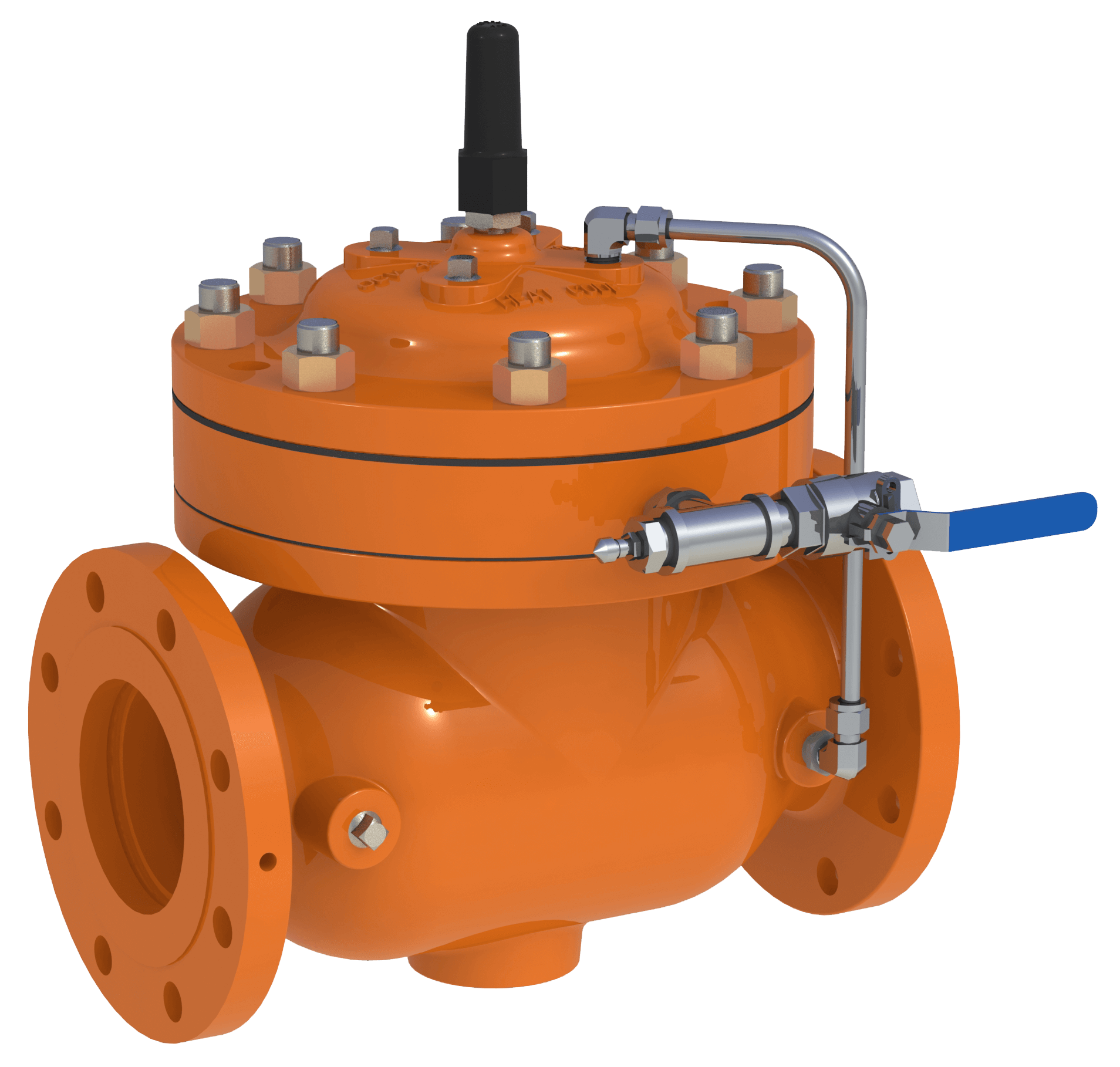
Hydraulic control valves are used to contain and transfer the flow and pressure of hydraulic fluid in hydraulic systems. There are many different designs of hydraulic control valves, including check, cartridge, directional, relief, safety, shut off and solenoid valves. Hydraulic control valves come in a variety of sizes and pressure ratings.
A wide range of styles crowds the hydraulic valve market, giving buyers plenty of specialized options. The hydraulic solenoid valve has a coil that is electrically activated when the flow of liquid changes in intensity, which then sends a signal to the plunger to cut off or release the flow. Proportional valves do a similar thing, by having an electric current alert the plunges when to stop or release, but are additionally able to control the output flow even while taking in more input flow.
For this reason, the hydraulic proportional valves, which are a major subcategory of control valves, are becoming more popular than solenoid valves on the market today. Another popular one in complex liquid systems is the directional control valve, which will direct the fluid to specific areas. Machines and devices that run on hydraulic power use hydraulic control valves. These valves are used in conjunction with hydraulic cylinders, pumps and motors. They are commonly found in those vehicles manufactured by the automotive, aviation, and construction industries.
In an open position, hydraulic valves permit the flow of fluid; when in a closed position, they prevent flow. Hydraulic control valves are used to prevent improper levels of pressure and fluid in hydraulic systems. The basic mechanics of all hydraulic control valves essentially remains the same; each is usually cylindrical and occasionally contained in a small square-shaped house, placed at the mouth of a pipe or on the head of a pump and contains a seat in the opening that cradles the plunger that may be a variety of shapes and sizes.
These various styles are mass produced in general cavity sizes, as well as being specially designed for certain out of the ordinary applications. The size of a hydraulic valve may vary from a fraction of a millimeter to three or four meters long. Whatever size, they are able to control the flow of liquid, whether it is thick like oil or thin like water. Some valves simply shut off flow when flow rates get too high, while others transmit signals to other valves in order to provide a systematic balance of flow.

The S50 Safety Shut Off valve is mainly used to avoid any damage to components as well as to avoid too high or too low pressure in the gas train. This could cause high financial losses and/or injured ...
Excavator pipe-rupture valves prevent uncontrolled cylinder movement in the event that a pipe or hose bursts. The ESV valve fulfills all of the requirements of the ISO 8643 and EN 474-5 ...
... base of an hydraulic cylinder, while the hose can be applied on the valve without any other components needed. The safety valves VUBA-DIN avoid an uncontrolled lowering ...
Hydraulic safety valves are made according to API 6A. When oil and gas leaking or firing, used for security protect on well site, the control system includes low pressure ...
Jereh Safety Valve is equipped with pneumatic, hydraulic or electric actuator, widely used in Christmas tree and surface manifold. In case of any emergency ...

At Prince Manufacturing Corporation we pride ourselves in our outstanding line of products. Our engineering expertise, state-of-the-art manufacturing equipment and strong employee work ethic contribute to the long-life and durability of our products. We have in-stock cylinders, valves, pumps and accessories for almost any application, and if we don"t, we"ll consult our highly trained engineers to custom design one today.
![]()
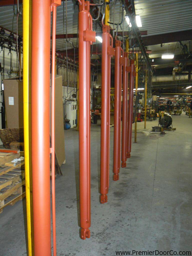
Our Industrial style cylinders are sized appropriately per door width and height. Featuring long stroke and extended mounting centers to cover the span of the door for rigid integrity. Our cylinders are custom made in small batches with high quality materials. Many hydraulic cylinders look alike. However its whats inside that counts.
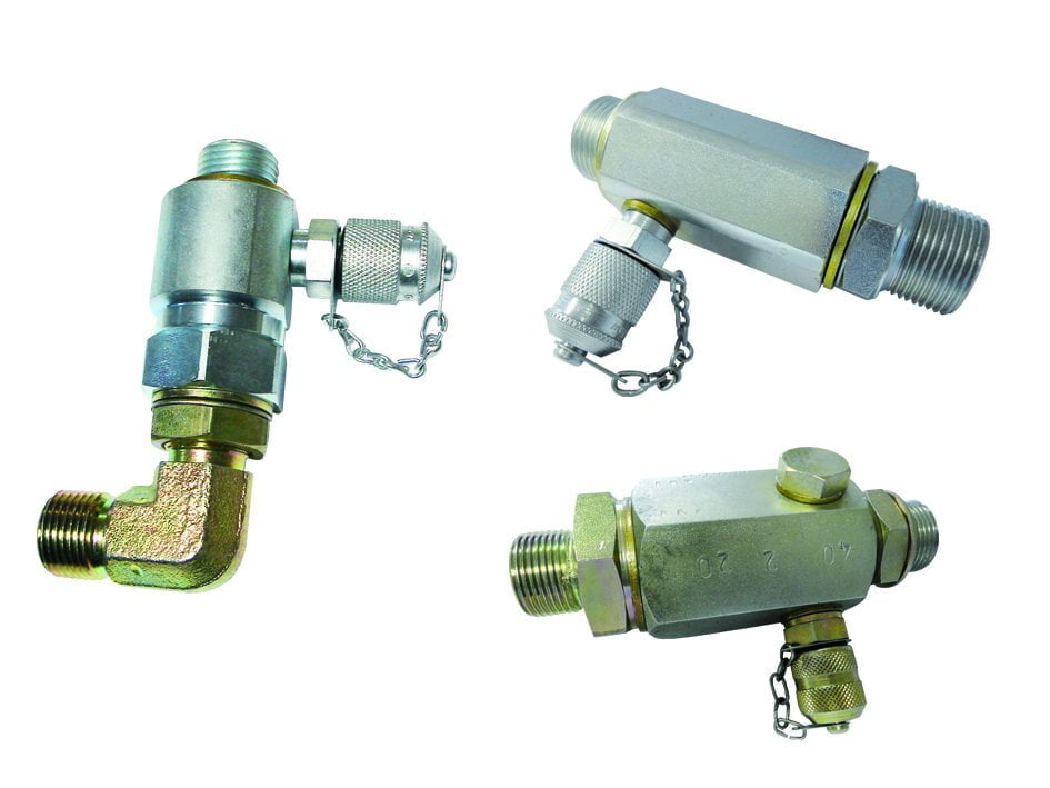
The Cross series relief valves have been designed to give long life and smooth performance at an economical price. The hydraulically dampened poppet uses differential areas to provide minimal variations between opening and full flow pressures.

The Cross SRC series dual differential type relief valves are used to protect equal size cylinders or motors from external or shock loads. Oil which passes from one relief valve flows directly to the opposite side of the circuit, thus preventing cavitation. The swing circuit on a backhoe is a good application example.
Load holding – When a hydraulic cylinder is required to hold its position for an extended period without drifting, load holding valves are the answer. Think a mobile crane outrigger that needs to maintain a level position or a manlift that is extended for work on utility lines.
Pressure relief – In certain situations, such as a significant temperature swing, load holding valves can provide pressure relief to avoid pressure intensification and system failure.
Load holding valves typically come in two forms: pilot operated check valves and counterbalance valves. Both valves lock the fluid in a cylinder to prevent drifting, but there are some key differences between the two.
Pilot-operated check valves, also known as pilot-to-open check valves, are non-modulating valves that are considered in operation to be either fully open or fully closed. They allow hydraulic fluid to flow into a cylinder but restrict flow out of the cylinder unless pressurized fluid is supplied through a pilot line.
P.O. check valves work well in load or position holding applications due to their typically near-zero leakage. They also prevent cylinder drift due to a slow leak or rapid motion due to a ruptured hydraulic hose. They can literally be a lifesaver.
But unlike their cousin, the counterbalance valve, a PO check valve is not capable of metering the oil flow through them and therefore do not function well with over-running loads. When lowering a load being acted on by gravity, a P.O. check valve may cause severe ratcheting of the cylinder and resultant shock in the hydraulic system.
A counterbalance valve is a modulating valve that not only acts as a load holding brake but is also able to maintain control over a load in motion. This is especially important in mobile applications, where an “over-center” load can make a cylinder over-speed the pump. The load tries to move quicker than the desired flow rate.
A counterbalance valve will only open enough to allow a load to move at a desired flow rate ensuring the load will not “run away” due to external forces, such as gravity. So, unlike a P.O check valve, a counterbalance valve can provide full flow for hoisting while metering flow to provide controlled lowering.
Another key difference and advantage to a counterbalance valve is its relief characteristic. In cylinders with high bore / rod ratios thermal expansion on the cap end can cause pressure on the annular side to rise beyond yield strength of the material which results in an intensification failure. This may materialize as a ballooned barrel, a collapsed rod, a blown-out gland or seal – or a combination of failures.
If the cylinder is designed with a counterbalance valve on both the extend and retract side, the retract counterbalance will open once pressure reaches the valve setting and allow the pressure to be relieved through the control valve. If the cylinder is designed with a pilot to open check valve, the pressure cannot be relieved, as there is no relief characteristic to the valve. The pressure will rise until material yield or seal failure occurs.
In applications where there are large swings in ambient temperature, such as desert locations, thermal expansion can cause cylinders equipped with pilot operated check valves to lock in position – even when commanded to move.
An external manifold has the benefit of easy replacement should something fail, as it is located outside of the cylinder. A load holding valve manifold can also be added to an existing hydraulic system quite easily if there is ample room for it. The main disadvantage here is that the external valve manifold is mounted externally and therefore can be subject to impact and the elements.
Direct integration allows the valves to be designed and housed right into the cylinder. The greatest benefit here is the reduced risk of external leakage or hose failure. There is flexibility in valve location to integrate with equipment and added protection from external hazards. However, integrating valves directly into a cylinder requires 2-3” of space which must be factored into the overall length and cylinder stroke. This is an easy task when designing a cylinder from scratch but can pose a challenge when integrating into an already-fabricated cylinder.
In load holding applications a P.O. check valve can be a suitable and a more economical choice. In applications that also require controlled lowering or the benefit of pressure relief, a counterbalance valve is the only solution and worth the extra cost.
There are many options when selecting load holding valves for your application. From basic single or dual valve design to complex circuits, we can provide a cost-effective solution for all applications and working pressures.

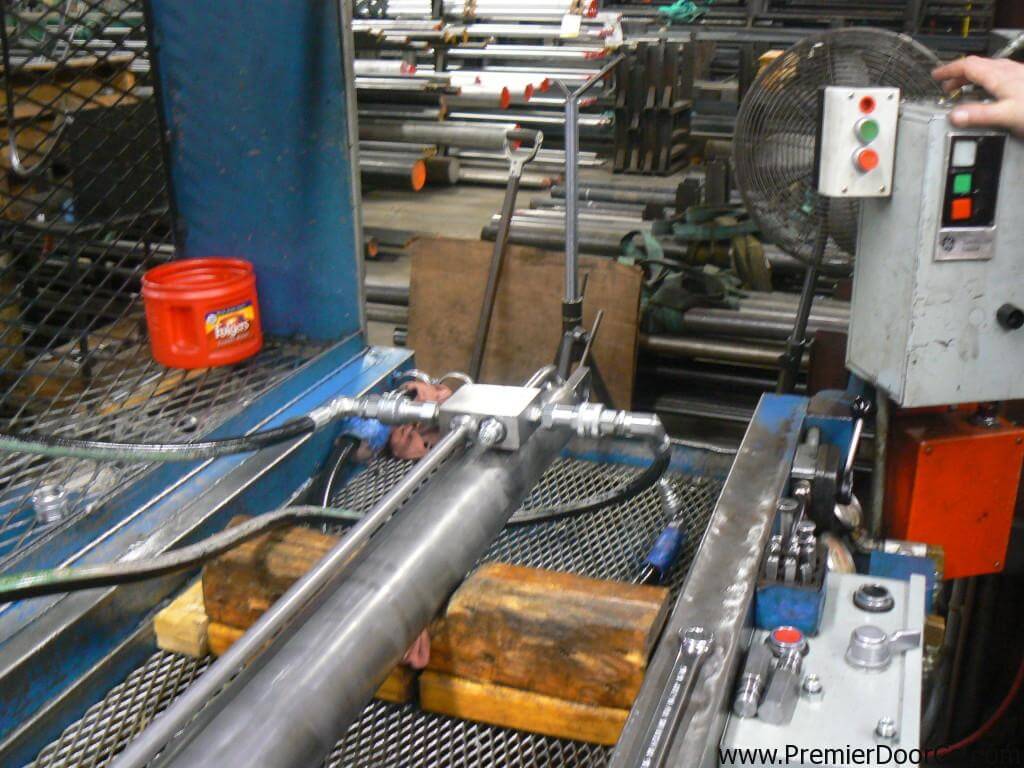
While conducting a hydraulic safety workshop for one of the largest equipment rental companies in the US recently, I was told, by a student, that a representative of an aerial lift manufacturer advised him to remove a cartridge valve from the base of a boom lift cylinder to relieve pressure from a boom cylinder after the engine failed.
In this instance, an aerial lift platform apparently tipped over. As it lay on its side, engine oil found its way into the engine cylinders. When righted, an attempt to start the engine proved fruitless because the engine had hydro-locked leaving the maintenance personnel wondering how to lower the boom.
Upon discussing the matter with the manufacturers technical experts, he was told to carefully screw the safety valve out until it was free of the o-ring seal, which would allow the oil to leak out past the threads thus allowing the boom to lower very slowly.
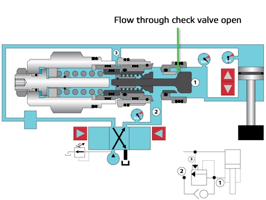
Imagine that the mast/boom on the machine in the illustration is in the raised position and the engine/hydraulic pump is disabled the pump provides the pressure and flow needed to lower the boom/mast safely.
The only way to lower the boom/mast is to remove the oil, which is trapped in the cylinder between the piston seals the safety locking valve. This leaves loosening and/or removing the valve as the only means of dissipating the unpredictable amount of stored energy from the cylinder - or to use the correct description - weight loaded accumulator!
A similar situation occurred at a mine in Globe, Arizona when a mechanic, following the advice of a factory expert, was screwing a safety valve out of its housing to lower the boom on an engine-disabled basket lift. Due to the fact that the threads restricted the leakage to a few drops per minute, the mechanic decided to, as he put it, give it another turn.
With only one or two threads left in the valve body, the pressure, and resultant force agianst the cartridge valve, sheared the threads, propelling it out unexpectedly. The ensuing jet of oil blew both the mechanic"s safety glasses and hard hat off and sent him reeling backwards to the ground. His colleagues scattered in all directions.
Figure 2Cartridge Valve Manufacturers Offer the Same Advice -While chatting with an applications engineer for one of the largest cartridge valve manufacturers in the U.S., I asked him what advice he offers personnel who are faced with the same dilemma - back the cartridge out and let the oil drip past the threads, was his rhetorical response he did admit that it was a dangerous procedure!Pressures and Flow Rates are Usually Unknown -A hydraulic cylinder, which is supporting a boom or a mast, is for all intents and purposes, a weight-loaded accumulator. The magnitude of the stored energy can be calculated by the weight (load), the area of the cylinder (s), and the cylinder rod stroke.
Lets say that the boom on a given crane weighs 4,000 lbs., and the area of the lift cylinder is 5 square inches. If the formula to calculate the pressure in the cylinder is force (weight) divided by area (piston), then the pressure is:
Lets say that the piston rod area is 2 square inches. The weight 4000 lbs divided by the area 2 square inches makes the pressure rise to an astounding 2000-PSI!Money is the Root of All Evil! -Ironically, the reason why maintenance personnel are subjected to these, and other, life-threatening hazards, is due to the fact that making a hydraulic system safe costs money, and while OSHA et al, look the other way when it comes to hydraulic safety, there is no reason to make the investment.
Another reason why aerial lift and scissor lift manufacturers get away with the safety issues is because less than 1% of the personnel who work on the hydraulic systems are properly trained untrained people will heed bad advice when it comes from the so-called experts after all, they must know what they are talking about because they designed the machine!Heed My Advice - DONT DO IT!!! -Let me make it abundantly clear removing a cartridge valve while it is under pressure could lead to severe injury, death, and/or substantial property damage. You are usually called upon to remove a cartridge valve because an engineer failed to design-in safety for a number of reasons:
Its your decision. Understand the reasons why the situation you are in has occurred in the first place, and then decide if you are willing to risk your life, and that of your colleagues, to compensate for poor engineering in concert with a blatant disregard for the safety of the people who work on and around this type of machinery.
If you are told to remove a cartridge valve plead ignorance ask for a demonstration! The only way to stop this problem in its tracks is to have the engineer, or the president of the respective company, come face-to-face with the wrath of the hot, pressurized oil.
I asked OSHA to intervene they were not interested. Remember, hydraulics is not a recognized occupational hazard. While OSHA et al, "talk the talk" about stored hydraulic energy, they dont "walk the walk" you are on your own choose wisely!
Ironically, there is a hydraulic safety product on the market that is designed specifically for the purpose of safely removing stored energy from hydraulic systems it only costs a few dollars! (www.safe-t-bleed.com)
Custom DutyShipping from Taiwan to : United States (US)HS Code: 841221 (Hydraulic Cylinders)The Custom Duty Rate is: 0.0%(The rate is for your reference only. Please check it with your local DHL, UPS, or Fedex)

Custom DutyShipping from Taiwan to : United States (US)HS Code: 841221 (Hydraulic Cylinders)The Custom Duty Rate is: 0.0%(The rate is for your reference only. Please check it with your local DHL, UPS, or Fedex)
Many hydraulic systems utilize a pressure relief valve to limit maximum system pressure. If the pressure is found to be too high, the system will use excessive input energy and the fluid may overheat. In addition, excessive pressure may stress components and create a very real danger to humans.
The purpose of a system relief valve is to prevent excessive pressure. The function of a relief valve is to divert as much of the system flow back to tank as needed in order to limit the pressure. A relief valve does not remove system pressure (as an unloading valve does). It prevents pressure from rising past a determined set point.
While some hydraulic systems may also include a special system pressure control (compensator) that changes the displacement of the pump, this post only deals with a system that utilizes a single pressure relief valve. In addition this post only features a basic hydraulic system and provides simplifies guidelines.
Please note that adjusting the pressure relief valve without sufficient training in hydraulic system maintenance and safety can result in damage to machinery and a threat to human life. Read and observe all cautions that are provided by your machine/system and component manufacturer, and follow all safety regulations in your jurisdiction.
A system relief valve is considered to be adjusted and set when the system pressure gauge reading is at the correct maximum pressure value, with all of the system flow passing through the relief valve back to tank.
In the example above the hydraulic motor is overloaded and stalled. The relief valve is clearly set to 1000 PSI as indicated on the gauge. (relief symbols shown in animated/active state)
In order to be sure that all of the flow is passing through the relief valve, pump flow must not be allowed to move through any other paths in the hydraulic system. How best to achieve this state should be laid out as a procedure in the manual that came with your machine. For teaching the concepts using these simplistic images, the hydraulic motor shaft has been overloaded in order to make sure that all pump flow will move through the relief valve.
A relief valve has a number of characteristics and operational states that are spoken about. One term that is often discussed is "cracking pressure", where the relief valve has just barely opened and is beginning to pass the smallest amount of flow.
Another term is "set pressure", which is when all of the pump flow is moving through the valve. The difference between the two pressures (causing the slope on the graph) is the "pressure override". The difference between cracking pressure and set pressure will vary by relief valve design and from one manufacturer to another.
For a relief valve with a narrow band of pressure override, a mere quarter (1/4) turn of the adjustment screw may change the pressure setting by 500 PSI (33 Bar) or more. Know these factors before making an adjustment.
There are methods to adjust a relief valve in-circuit while running, or on a test bench using the cracking pressure and then factoring in the pressure override value. The details of these procedures are beyond the scope of this post.
Again, take all precautions and become well trained and practiced on simpler, lower pressure systems and simulations before making relief valve adjustments on large and high pressure systems.
Carl grew up looking after the machinery and equipment used in timber and lumber processing. After some early career years spent in public education, a unique enterprise was born.Carl and team spend their days demystifying complexmachinery, creating interactive art and software that aids learning, and conducting instructor-led maintenance training and hydraulic system consulting, globally, for a wide range of heavy industries.


 8613371530291