
hydraulic safety valve symbol free sample
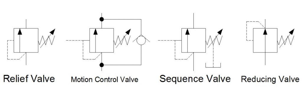
In Hydraulic Symbology 101 (read it here first), I covered the basic square used for pressure valves and also showed the most stripped-down versions of the two most commonly used pressure valve symbols, the relief valve and the pressure reducing valve. In this edition of Hydraulic Symbology, I’m going to cover the four primary pressure valves; the relief valve, motion control valve, sequence valve and reducing valve. Each is based on the same square symbol but are used quite differently in both circuits and real-life function.
Shown below are the quartet referenced from the same angle as each other. Each shows the basic square with a vertical arrow, abreast of a pilot line to the left and a spring to the right. The dashed line stands for a pilot signal, which is a fluid column of pressure energy used to push or act upon other components internal to the valve. The relief valve is normally closed (non-flowing). As pressure rises in the bottom port, energy pushes around to the pilot line to the left, but the valve is still closed. As the pressure continues to increase, the force pushing against the left side of the arrow starts to overcome the spring force applied from the right. When pilot pressure creates enough force, it can overcome spring pressure to slowly open the valve.
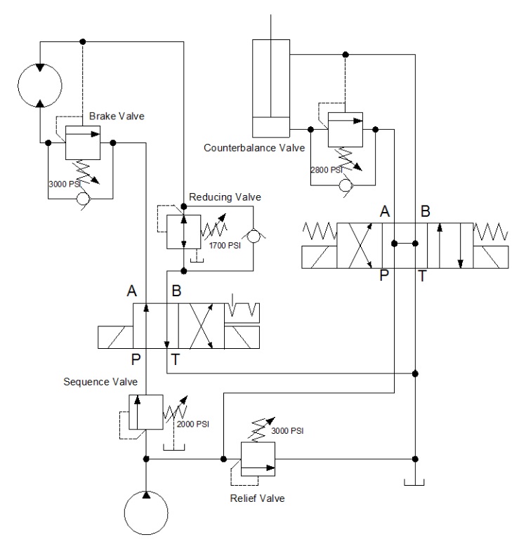
The below example shows a circuit with all four types of pressure valves used. It looks like a lot going on, but I’m going to break them all down one by one so they make sense. The relief valve teed into the right after the pump is drawn just as the relief valve above, and it operates under the same principle. The spring is pushing the valve closed with 3,000 psi of force, and in this circuit, it acts as the maximum limit pump pressure can achieve before being exhausted to tank.
Sequence valves are not much different from relief valves, and this is at once obvious by their similar appearance. This sequence valve downstream of the pump is exactly the same as the relief save for the drain line and reduced pressure setting. A sequence valve is purposed to provide a secondary flow path which occurs in sequence to a parallel function. In other words, when the cylinder in this application extends to the end of stroke, pressure will rise immediately. When pressure hits 2,000 psi, our sequence valve opens, diverting all pump flow to rotate the motor while the cylinder remains stalled and as long as its directional valve remains energized.
The sequence valve drain line is required to keep the valve’s performance consistent. Because the sequence valve experiences pressure on both ports, internal leakage allows pressure buildup inside the spring chamber which is additive to spring pressure. Without a drain, the pressure setting could rise or the valve could even lock up altogether. The key difference between a sequence valve and relief valve is the existence of this drain. A sequence valve makes an outstanding relief valve, in fact.
The pressure reducing valve is plumbed in just past the directional valve in the B-port. You’ll notice immediately how different this valve is than the others, and the extra astute will have noticed two differences, actually. The pilot line is drawn differently, this time showing its pressure signal originating downstream of the valve. This important contrast allows the valve to reduce downstream pressure to protect the actuator or sub-circuit beyond.
The reducing valve also differs in that it is normally flowing in its neutral state. Fluid is free to pass and allow the motor to spin, and not until downstream pressure from the motor rises to above the 1,700 psi setting of the valve does is start to close. The pilot line senses downstream pressure and starts to move the arrow to the right, choking flow to the motor. This reduced flow also reduces pressure, but it does so smoothly and with little drop in velocity. The effect is that downstream pressure is simply reduced.
You’ll notice in this example, there is also a check valve allowing flow to bypass the reducing valve altogether. This ensures the motor will experience little or no backpressure when it rotates in the opposite direction. Sometimes the reverse-flow check valve is not required, but it makes for good practice.
The last pressure valve to be discussed today is the motion control valve, which in my example is broken down into the brake valve and the counterbalance valve. The brake valve is used in motor applications as seen above. The valve is also very similar to the relief valve in design, and in fact, could still be used as one (as is the case for all pressure valve aside from the reducing valve). The reverse flow check valve allows free flow into the motor, allowing it to freely spin clockwise when the directional valve is left in its current detented position.
When the directional valve is reversed, however, the check valve blocks free flow and oil must now flow through the brake valve. This valve, you’ll notice, has two separate pilot lines merging at the same point on the valve. It has the same direct acting pilot line that rounds the corner, but there is an additional pilot source drawn from the opposite port of the motor. These dual pilot sources add interesting functionality to the brake valve in that it is both internally and externally piloted.
The internal, direct-acting signal will ensure the motor won’t move until a combination of load and pump pressure pushes through the motor to the tune of 3,000 psi. This allows the motor to stay “braked” while pump flow is non-existent. However, a direct-acting brake control valve is an inefficient method to control motion.
This valve has a trick up its sleeve — the surface area the external pilot works against is larger than the area of the direct acting side. The ratio of areas is often 4:1 but can be upwards of 8:1. The result is the pilot pressure needs to a quarter of work pressure, reducing energy lost to the brake valve. The brake valve is essentially braking to the tune of 3,000 psi, but opening to provide flow when the opposite port sees 375-750 psi. The valve uses pilot pressure as permission to open and allow flow, preventing unintended movement of the motor.
Lastly, we arrive at the motion control valve labelled counterbalance valve. It’s typically one and the same as a brake valve but used in cylinder applications. This example shows a relief valve set to 2,800 psi and is plumbed to the cap port of the cylinder. The reverse flow check valve ensures the cylinder will extend with little pressure drop, but when the directional valve is placed back in neutral, the counterbalance valve remains closed so the cylinder will not accidentally retract.
The counterbalance valve also has a pilot ratio enabling the valve to open once it senses pilot energy from the rod port, preventing accidental retraction. Counterbalance valves also work well on the rod port of a cylinder, which prevents overrunning loads as a cylinder moves “over center,” which is a condition of pulling forces on the rod.
Both examples of these motion control valves could have been employed with spring chamber drain ports, just as with the sequence valve. The drain keeps the spring chamber free from additional pressure, but in the case of this circuit, the open line to the reservoir through directional valves is enough to prevent excessive pressure. It’s when both ports of the pressure valve are continuously pressurized that a drain or vent is absolutely required.
There are many variations of pressure valves not covered here, but those will be discussed in a later episode. In Hydraulic Symbology 204, I’ll cover the essentials of flow control valves, including how they’re drawn and where they’re used.
![]()
Pilot operated check valves have a small pilot line, shown as a dashed line, that is used to lift and open the check valve and allow flow back through the valve. A common format is the double PO check sandwich plate valve, shown below, that is often used with CETOP directional valves. This allows free flow in both directions when pressure is applied to one side but when the directional valve is closed and no pressure is applied then both check valves close, holding the load in place.
![]()
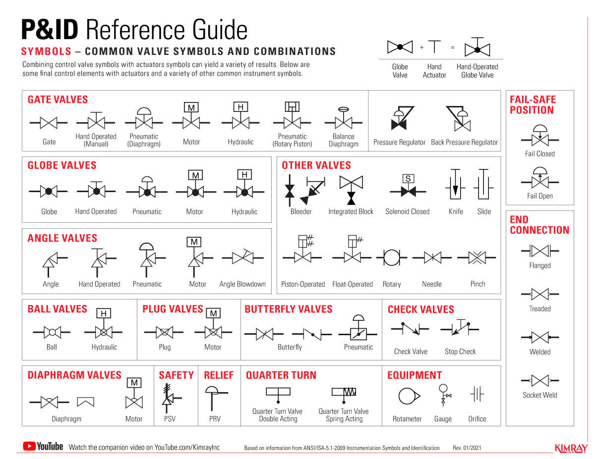
Engineers use control valve symbols to identify the type of control valve they want to specify for a given application. In this article, we will identify the most commonly used control valve symbols.
The control valve symbols on a P&ID differ depending on the type of valve specified for the application. Each P&ID has its own legend that identifies the symbols for the various equipment.
An engineer may also include specific details below the control valve symbol. These details may include the size, function, pressure rating, and connection type of the valve.
Piping and instrumentation diagrams (P&IDs) are conceptualized during the development and design stages of chemical, physical, electrical and mechanical processes. Everything from ball valve symbols to communication lines are included in a P&ID in order to lay out the proper direction for a process control installation.
In this article, we highlight some of the most common P&ID valve symbols, process lines, end connections and other vital components. Before you dive in, download a PDF version of the symbols listed in this article.
The symbols for these components aren’t drawn to scale and aren’t intended to be dimensionally accurate. Symbols can also be marked with words, letters and numbers for more detail.
The International Society of Automation (ISA) created the ANSI/ISA-5.1-2009 standard that defines the proper ways to use symbols in a P&ID. Although these standards are in place, there may be variations of certain symbols used across industries or companies. But, since all components in a P&ID use text or numbers for further identification, having a basic understanding of the symbols should not be an issue.
A 2-way, on/off valve is symbolized by two equilateral triangles that point toward each other. These valves use varying types of lines to represent different types of valves. The direction of the flow is shown by an arrowhead at the end of the line.
For multi-port valves, additional triangles are added to the symbol. L-port and T-port valves are depicted by lines within the ball symbol. The flow path is depicted by small arrows by the symbol.
The type of actuation is depicted with lines protruding from the center of the valve. A small symbol appears on top of the line for further identification. Electric and hydraulic actuation are shown with letters.
The type of connection for a valve (flanged, threaded, welded or socket weld) is displayed using perpendicular lines, circles and squares. For example, the perpendicular lines in a flanged connection show that the valve can be removed without affecting the pipe. Unfilled circles represent temporary threaded connections while permanent welded connections are depicted by filled-in squares. Socket welded connections are displayed using unfilled squares.
Gemini Valve manufactures, distributes and supports a full selection of performance-engineered ball valve products, including custom ball valves. For more information or to speak with a specialist, contact us here.
![]()
A piping and instrumentation diagram (P&ID) is a graphic representation of a process system that includes the piping, vessels, control valves, instrumentation, and other process components and equipment in the system. The P&ID is the primary schematic drawing used for laying out a process control system’s installation. As such, the P&ID is crucial in all stages of process system development and operation.
There are standard symbols used to represent the components in these diagrams. It is important to note that these symbols are NOT to scale and are NOT dimensionally accurate. They are merely used to represent a certain type of component. These symbols are also labeled with words, letters, and numbers to further identify and specify the components that they are representing. Another important consideration is that the diagrams do NOT always represent the physical locations and proximity of each component. The purpose is NOT to serve as a floor plan or map of the system, it is to illustrate the process of the system.
The generic symbol for a 2-way valve is two triangles pointing to each other with the tips of the inner points touching. The pipe lines are represented by lines connecting to each side of the valve symbol. Various types of lines are used to represent different pipes, tubes, and hoses. These examples use single solid lines which represent simple rigid pipes or tubing. Typically all pipes will run either vertically or horizontally and use only right angles. The direction of flow is indicated by an arrowhead at the end of the line where it meets the next component as well as at every 90 degree turn.
All of the valves represented above are 2-way inline valves that are used for flow control, either on/off or throttling. For Multi-port valves, such as 3-way and 4-way, the structure of the symbol is similar, having a triangle to represent each port or “way”.
3-way and 4-way ball valves can contain additional detail that defines the type of ball drilling which is either a “T” or “L” port ball. Another detail that may be represented in the diagram is the flow path in the non-actuated or de-energized state. This is shown using small arrows next to the symbol as shown below.
The method of actuation is defined by a line coming up from the center of the valve with a small symbol, many times containing a letter, at the top of the line. Here are some examples of ball valves with different methods of actuation.
When the actuator has a fail-safe position, it is represented by an arrow on the line between the valve and actuator. Another method used to represent the fail position is with two letters “FO” or “FC”.
End connections can be represented generically with the lines representing the pipes going directly into the valve as in all of the examples above. Connections may also be explicitly defined using various other methods. Flanged connections are represented as shown below – where the pipes have perpendicular lines at their ends that run parallel to the sides of the valve symbol with a small space between them. This illustrates that the valve can be removed without cutting the pipe. Semi-permanent threaded connections are shown with small hollow circles at the connection point. Permanent welded connections are represented with small squares instead. If the connection is socket weld, the square is hollow or un-filled.
Despite the fact that there is a strict set of standards defined for these symbols, you will find various ways of representing certain valves. You will also find that there are blatant discrepancies between some valve types across various libraries, industries, and companies. This issue is not that problematic since all components are also described by text, a part number (unique model), a tag number (specific component in the system), and are defined in detail in a key or legend that goes along with the drawing. As long as you remain consistent throughout your drawings, the P&ID diagram will be acceptable and understandable by all who work with it.
The list goes on and on… There are literally hundreds of symbols that represent all components used in process control systems. Heat exchangers, coolers, boilers, filters, etc.etc. We have created a library of P&ID symbols that includes the most common components used in piping and instrumentation diagrams.
This type of bubble is also used to define the function of final control elements such as valves. This is done with a callout line pointing to the symbol for the control element. The letters and numbers inside the bubble are described below.
This is followed by loop number, which is unique to that loop. For instance FIC045 means it is the Flow Indicating Controller in control loop 045. This is also known as the “tag” identifier of the field device, which is normally given to the location and function of the instrument. The same loop may have FT045 – which is the Flow Transmitter in the same loop. Below are some examples of complete symbols for a few instruments in the same loop.
Create fluid power diagrams in Visio Professional or Visio Plan 2 to document hydraulic or pneumatic control systems, such as those used in factory automation systems, heavy machinery, or automobile suspension systems.

Hydraulics engineers regularly encounter these diagrams, but these symbols can be daunting to interpret if you have limited experience with schematics and the fluid power industry.
On this page, Carr Lane ROEMHELD provides a comprehensive table outlining the definitions of each symbol used in a hydraulic diagram. Engineers can use this page as a reference to determine common schematic symbols used in fluid power, hydraulics, pneumatics, diagrams and circuits.
Check valves are the simplest form of hydraulic devices in that they permit free oil flow in one direction and block oil flow in the opposite direction. Check valves may also be used as a directional or pressure control in a hydraulic system.
In Figure 1, oil is flowing in from the left side port, through the check valve and out the right side port. If the pressure equalizes or is higher in the right side port, the check valve will close and block flow in the opposite direction.
The spring rating varies based on how the valve is used in the system. One of the most common locations for a check valve is immediately downstream of the hydraulic pump (Figure 2). Notice that no spring is shown with the check valve symbol.
When used in this application, the spring pressure rating is usually 1-5 pounds per square inch (psi) and therefore not shown with the symbol. In this case, the valve is used as a directional control in that it allows oil flow from the pump to the system but blocks flow in the reverse direction. This is commonly called a pump isolation check valve. This valve serves four purposes within the system, which are detailed below:
The check valve will block pressure spikes back to the pump. Depending on the pressure, oil flows from the pump to the system at a speed of 15-30 feet per second. When a directional is de-energized to block flow or a cylinder fully strokes, the oil is rapidly deadheaded. The pressure in the line can quickly increase by two to three times. The check valve should then close and block the pressure spikes to the pump.
I recall a plywood plant changing four pumps due to cracking of the pumps’ housings. This occurred over a week’s time on the debarker hydraulics. When the plant ran out of pumps, the staff finally took out the check valve and found that the piston and spring were no longer in the valve.
This $150 check valve cost the company $15,000 in replacement pumps and another $50,000 in machine downtime. That was one expensive check valve. The truth is that if one mechanic had looked at the schematic and known why the check valve was in the system, the replacement of the pumps and subsequent expenses would have been avoided.
When a system is shut down, it is important to maintain oil in the lines. In many cases, the pump is mounted below the level of the system valves, cylinders and motors. The check valve downstream of the pump will prevent the lines from draining once the electric motor is turned off. If the oil in the lines drains through the pump and into the reservoir, a vacuum will occur.
Air will be pulled into the lines through the O-rings and seals of the valves and actuators. This can create issues when restarting the system, as the air will need to be bled out.
Some systems have a hydraulic accumulator installed downstream of the pump and check valve. When the system is turned off, there is pressurized fluid inside the accumulator. The check valve will block flow from the accumulator, preventing the reverse rotation of the pump.
You can observe the pump shaft or electric motor fan to verify that the check valve is good. Please note that all systems using an accumulator should have a method of bleeding the hydraulic pressure down to zero psi when the system is turned off.
On many systems, one pump is used as a backup or spare (Figure 3). Each pump will have a check valve at the pump outlet port. The check valve will block flow from the online pump to the offline pump, preventing reverse rotation.
The timeline was so critical due to downtime costs that the pump was still warm when they received it back from the factory. Just prior to installing the pump, we removed the check valve in the case drain line and found it stuck in the closed position. This prevented the oil in the pump case from draining, which resulted in blowing out the seal.
Frequently, a check valve is used for pressure control. A common application is to employ it as a relief valve to protect a heat exchanger (as shown in Figure 4). In this case, the spring rating is usually 65-100 psi.
If the oil is cold, the inlet pressure to the cooler may reach the check valve’s rating. The check valve will then open and direct the pump volume around the cooler. A check valve will also provide protection for an air-type heat exchanger if the tubes become contaminated.
A few years ago while teaching a class at a sawmill, I observed the students doing their hands-on exercises on the edger. Although a check valve was shown on the schematic to protect the air cooler, the lines to the check valve were plugged off. I asked one of the mechanics about it. He said the check valve was taken off years ago and that they had changed the cooler the week before because of ruptured tubes.
When troubleshooting hydraulic systems, most everyone looks for something large to be the problem, such as a pump, valve or cylinder, but every component has a function. Be sure you understand the purpose of the check valves in your systems.
Al Smiley is the president of GPM Hydraulic Consulting Inc., located in Monroe, Georgia. Since 1994, GPM has provided hydraulic training, consulting and reliability assessments to companies in t...
Out of any topic under the patio-sized umbrella of fluid power, hydraulic symbology garners the most requests from those wishing to learn more about fluid power. Reading any schematic with more than three symbols can be daunting if your experience is limited. But it’s not impossible to learn. In fact, it only takes a basic level understanding of how symbols work and how they’re arranged in a diagram. One challenge – even if you’ve memorized every symbol in the library – is understanding why a particular symbol is used in a circuit; that part is hard to teach and just comes with experience.
The third most common line you will see is the simple dashed line. This is a dual function line, representing both pilot and drain lines. A pilot line in both representation and function uses hydraulic energy to signal or operate other valves. Learning to comprehend pilot lines is key to understanding advance hydraulic schematics. As a drain line, the dashed line simply represents any component with leakage fluid needing a path represented in the drawing.
If we get slightly more advanced than your basic line, we have three other common shapes used in hydraulic schematics. These are the circle, square and diamond. Ninety nine percent of hydraulic symbols use one of these three as a foundation. Pumps and motors of every kind are drawn using a circle, as are measuring instruments. Valves of every kind use the basic square as a start. Some are simply one square, such as pressure valves, but others use three joined squares, such as with a three-position valve. Diamonds are used to represent fluid conditioning devices, like filters and heat exchangers.
Let’s assume the relief valve is set to 2,000 psi. You’ll have noticed the dashed line coming from the bottom of the symbol, rounding the corner and is attached to the left side. This dashed line indicates the valve is directly operated by the pressure at its inlet port, and that pilot fluid can affect the valve by pushing the arrow to the right. The actual valve has no arrow, of course, but as is the nature of hydraulic symbols, just represents a visual model of what occurs. As pressure in the pilot line approaches 2,000 psi, the arrow is pushed until the valve reaches the centre, allowing fluid to pass, which in turn reduces pressure until upstream is 2,000 psi.
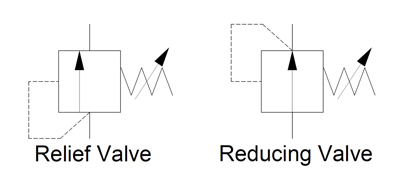
The pressure reducing valve is the only normally open pressure valve in hydraulics. As you can see, it’s very similar to the relief valve, save two changes in the symbol. Firstly, the arrow shows it flows in its neutral position, whereas the relief valve is blocked. Secondly, it gets its pilot signal from downstream of the valve. When downstream pressure rises above the spring setting value, the valve closes, preventing incoming pressure from reaching the downstream path, which allows pressure to decay back to below the pressure setting.
The basics of hydraulic symbology are quite easy, but I’ve only scratched the surface. There are many specialized symbols representing things like electronics, accumulators, various cylinders and ball valves, which I don’t have the room to show. Furthermore, each symbol I’ve shown represents a small portion of the modifications possible to each; there is probably a hundred or more ways to represent a hydraulic pump with a schematic symbol.
Finally, the way in which hydraulic symbols are combined to create a complete schematic representing an actual machine is endless. I recommend you spend time reading hydraulic schematics to interpret the symbols, whenever you have time. Not only will you discover unique symbols, but you’ll come across unique ways to use old symbols and components in a hydraulic circuit.


 8613371530291