
hydraulic safety valve symbol in stock
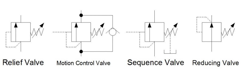
In Hydraulic Symbology 101 (read it here first), I covered the basic square used for pressure valves and also showed the most stripped-down versions of the two most commonly used pressure valve symbols, the relief valve and the pressure reducing valve. In this edition of Hydraulic Symbology, I’m going to cover the four primary pressure valves; the relief valve, motion control valve, sequence valve and reducing valve. Each is based on the same square symbol but are used quite differently in both circuits and real-life function.
Shown below are the quartet referenced from the same angle as each other. Each shows the basic square with a vertical arrow, abreast of a pilot line to the left and a spring to the right. The dashed line stands for a pilot signal, which is a fluid column of pressure energy used to push or act upon other components internal to the valve. The relief valve is normally closed (non-flowing). As pressure rises in the bottom port, energy pushes around to the pilot line to the left, but the valve is still closed. As the pressure continues to increase, the force pushing against the left side of the arrow starts to overcome the spring force applied from the right. When pilot pressure creates enough force, it can overcome spring pressure to slowly open the valve.
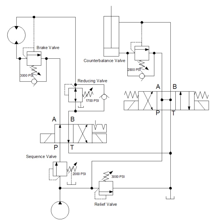
The below example shows a circuit with all four types of pressure valves used. It looks like a lot going on, but I’m going to break them all down one by one so they make sense. The relief valve teed into the right after the pump is drawn just as the relief valve above, and it operates under the same principle. The spring is pushing the valve closed with 3,000 psi of force, and in this circuit, it acts as the maximum limit pump pressure can achieve before being exhausted to tank.
Sequence valves are not much different from relief valves, and this is at once obvious by their similar appearance. This sequence valve downstream of the pump is exactly the same as the relief save for the drain line and reduced pressure setting. A sequence valve is purposed to provide a secondary flow path which occurs in sequence to a parallel function. In other words, when the cylinder in this application extends to the end of stroke, pressure will rise immediately. When pressure hits 2,000 psi, our sequence valve opens, diverting all pump flow to rotate the motor while the cylinder remains stalled and as long as its directional valve remains energized.
The sequence valve drain line is required to keep the valve’s performance consistent. Because the sequence valve experiences pressure on both ports, internal leakage allows pressure buildup inside the spring chamber which is additive to spring pressure. Without a drain, the pressure setting could rise or the valve could even lock up altogether. The key difference between a sequence valve and relief valve is the existence of this drain. A sequence valve makes an outstanding relief valve, in fact.
The pressure reducing valve is plumbed in just past the directional valve in the B-port. You’ll notice immediately how different this valve is than the others, and the extra astute will have noticed two differences, actually. The pilot line is drawn differently, this time showing its pressure signal originating downstream of the valve. This important contrast allows the valve to reduce downstream pressure to protect the actuator or sub-circuit beyond.
The reducing valve also differs in that it is normally flowing in its neutral state. Fluid is free to pass and allow the motor to spin, and not until downstream pressure from the motor rises to above the 1,700 psi setting of the valve does is start to close. The pilot line senses downstream pressure and starts to move the arrow to the right, choking flow to the motor. This reduced flow also reduces pressure, but it does so smoothly and with little drop in velocity. The effect is that downstream pressure is simply reduced.
You’ll notice in this example, there is also a check valve allowing flow to bypass the reducing valve altogether. This ensures the motor will experience little or no backpressure when it rotates in the opposite direction. Sometimes the reverse-flow check valve is not required, but it makes for good practice.
The last pressure valve to be discussed today is the motion control valve, which in my example is broken down into the brake valve and the counterbalance valve. The brake valve is used in motor applications as seen above. The valve is also very similar to the relief valve in design, and in fact, could still be used as one (as is the case for all pressure valve aside from the reducing valve). The reverse flow check valve allows free flow into the motor, allowing it to freely spin clockwise when the directional valve is left in its current detented position.
When the directional valve is reversed, however, the check valve blocks free flow and oil must now flow through the brake valve. This valve, you’ll notice, has two separate pilot lines merging at the same point on the valve. It has the same direct acting pilot line that rounds the corner, but there is an additional pilot source drawn from the opposite port of the motor. These dual pilot sources add interesting functionality to the brake valve in that it is both internally and externally piloted.
The internal, direct-acting signal will ensure the motor won’t move until a combination of load and pump pressure pushes through the motor to the tune of 3,000 psi. This allows the motor to stay “braked” while pump flow is non-existent. However, a direct-acting brake control valve is an inefficient method to control motion.
This valve has a trick up its sleeve — the surface area the external pilot works against is larger than the area of the direct acting side. The ratio of areas is often 4:1 but can be upwards of 8:1. The result is the pilot pressure needs to a quarter of work pressure, reducing energy lost to the brake valve. The brake valve is essentially braking to the tune of 3,000 psi, but opening to provide flow when the opposite port sees 375-750 psi. The valve uses pilot pressure as permission to open and allow flow, preventing unintended movement of the motor.
Lastly, we arrive at the motion control valve labelled counterbalance valve. It’s typically one and the same as a brake valve but used in cylinder applications. This example shows a relief valve set to 2,800 psi and is plumbed to the cap port of the cylinder. The reverse flow check valve ensures the cylinder will extend with little pressure drop, but when the directional valve is placed back in neutral, the counterbalance valve remains closed so the cylinder will not accidentally retract.
The counterbalance valve also has a pilot ratio enabling the valve to open once it senses pilot energy from the rod port, preventing accidental retraction. Counterbalance valves also work well on the rod port of a cylinder, which prevents overrunning loads as a cylinder moves “over center,” which is a condition of pulling forces on the rod.
Both examples of these motion control valves could have been employed with spring chamber drain ports, just as with the sequence valve. The drain keeps the spring chamber free from additional pressure, but in the case of this circuit, the open line to the reservoir through directional valves is enough to prevent excessive pressure. It’s when both ports of the pressure valve are continuously pressurized that a drain or vent is absolutely required.
There are many variations of pressure valves not covered here, but those will be discussed in a later episode. In Hydraulic Symbology 204, I’ll cover the essentials of flow control valves, including how they’re drawn and where they’re used.
![]()
Hydraulic symbols provide a clear representation of the function of each hydraulic component. Laying each symbol out on the page in the same sequence the components are used in the circuit allows people to understand the complete function of the hydraulic equipment.
Poppet, one-way, shuttle, or check valves are shown as a ball sitting on a seat. Pass flow through the seat and the valve opens. Pass flow from the ball side and the valve will close.
Poppet or check valves have a physical seat that the valve presses against. This positive connection may exhibit zero, or more likely a very small leakage across it.
In many cases, these are the cheapest and most simple valves but they also have the potential to be the largest, most complicated, expensive, and difficult to control.
Most hydraulic components are controlled when pressure is applied to one side of a piston or another. In the case of cylinders, the force generated by the piston will move and drive the load. In the case of a directional valve, the force is used to move a spool which opens different passageways to allow the fluid to flow along different pipelines.
Spool valves rely on tiny clearances to allow them to move freely. These spool clearances are small enough to hold the pressure but still large enough to allow a small amount of fluid to leak past. Cylinder pistons include seals which will exhibit much smaller leakages.
An orifice is just a small hole, either fixed or adjustable. With increasing flow across an orifice there will also an increasing pressure drop across it, this pressure is commonly used to open or close other spool valves or poppets. Alternately if a system has a specific set pressure then the orifice might be used to control the flow rate along its pipework.
Squares and rectangles form the basis of pressure and directional control valves. A single box for pressure control and multiple boxes for directional control.
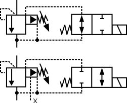
The valve sits between a hose and a cylinder. It is drawn as a two-position valve with an adjustable orifice in one position and a one-way check valve in the other. A spring holds it in one position but there are pressure feed pilot lines (dotted lines) feeding each end of the valve from opposite ports on the valve. This means that at low speeds while lowering and always while raising the cylinder, the valve stays open. However, if the hose was to break the cylinder started dropping quickly, the pressure difference across the orifice would cause the valve to switch, such that the check valve would block the pipeline. This would stop the cylinder from falling further. Therefore this is a hose burse safety protection valve.
The check valve is used to isolate the pump from backflows from the circuit, it also helps to keep the pump primed if components are removed. As the orifice size is reduced the pressure upsteam of the orifice will increase. The pressure is also sensed on one end of the directional valve (along dotted line) which will push the valve spool against the spring and therefore vent the circuit, maintaining a constant pressure on the pump.
A hydraulic circuit represents all the hydraulic components in a system. This includes the arrangement of the components and the behavior of the system as a whole in a universally accepted symbolic manner. In this article we will discuss the most common hydraulic symbols as represented in ISO 1219-1:2012. Armed with knowledge of how basic hydraulic components are represented in the hydraulic circuit; one can understand a wide range of different hydraulic symbols, representing components performing similar tasks with minor modifications.
A hydraulic reservoir stores hydraulic fluid. This is a must-have component in any hydraulic system. All hydraulic reservoirs are open to the atmosphere except in the case of those used in aircraft and submarines.
A hydraulic pump converts electrical and/or mechanical energy into hydraulic energy. The lower end (suction side) of a pump is connected to the hydraulic reservoir, the upper end is connected to the remaining circuit. The dark upper triangle in these hydraulic symbols indicates fluid going out of the system and hence represents a pump.
In the case of the hydraulic motor, the dark triangle is inverted indicating that the fluid is entering into the system. A hydraulic motor converts hydraulic energy into mechanical energy.
System output is represented by an arrow at 450 – this can be adjusted, In other words, that the pump/motor can deal with variable flow rate per shaft rotation. Most industrial applications use electric motors as prime movers to rotate hydraulic pumps. The electric motor is represented by the letter M inside of a circle. The curved arrow represents the direction of shaft rotation.
A pressure relief valve is a NC (normally closed) type safety valve which operates when system pressure increases above a maximum working pressure. The normally closed position is indicated by the arrow away from the center line. The dashed line indicates that the system pressure acts against spring force for valve actuation.
A direction control valve is a vital component in a hydraulic system. It controls the actuator’s position and direction by controlling the fluid flow into the actuator. Therefore direction control valves can be designated by number of ports and number of positions and are selected based on the application.
The central position is a neutral position and various neutral positions are available depending upon the application. All ports closed will increase the system pressure to the maximum – actuating the pressure relief valve. Whereas all ports connected in the neutral position will relieve the system by diverting fluid from the pump to the tank directly.
DCV can be distinguished depending upon the type of actuation. Hand levers, mechanical systems or solenoids are used to change the valve’s position. A spring is used to return to a neutral position.
The flow control valve is used to control the flow rate as well as the speed of the actuator. The position of flow control valve will lead to varied system behavior – an arrow representing the adjustable flow control.
A pressure indictaor is used to measure hydraulic pressure at any one point. Hence it is generally connected between the hydraulic pump and direction control valve
First of all you can see the electric motor driving the fixed delivery hydraulic pump in the above circuit. A safe pressure level is maintained using the pressure relief valve which is connected after the pump.
4/3 Direction control valve is being actuated by a solenoid control with all the ports are closed during the neutral position. In the figure, the DCV is in its 1st position and hence pressurized liquid will flow towards the right side of actuator. The left side of the actuator is connected to a reservoir meaning the actuator will move towards the left side.
Out of any topic under the patio-sized umbrella of fluid power, hydraulic symbology garners the most requests from those wishing to learn more about fluid power. Reading any schematic with more than three symbols can be daunting if your experience is limited. But it’s not impossible to learn. In fact, it only takes a basic level understanding of how symbols work and how they’re arranged in a diagram. One challenge – even if you’ve memorized every symbol in the library – is understanding why a particular symbol is used in a circuit; that part is hard to teach and just comes with experience.
The third most common line you will see is the simple dashed line. This is a dual function line, representing both pilot and drain lines. A pilot line in both representation and function uses hydraulic energy to signal or operate other valves. Learning to comprehend pilot lines is key to understanding advance hydraulic schematics. As a drain line, the dashed line simply represents any component with leakage fluid needing a path represented in the drawing.
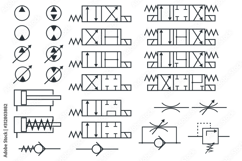
If we get slightly more advanced than your basic line, we have three other common shapes used in hydraulic schematics. These are the circle, square and diamond. Ninety nine percent of hydraulic symbols use one of these three as a foundation. Pumps and motors of every kind are drawn using a circle, as are measuring instruments. Valves of every kind use the basic square as a start. Some are simply one square, such as pressure valves, but others use three joined squares, such as with a three-position valve. Diamonds are used to represent fluid conditioning devices, like filters and heat exchangers.
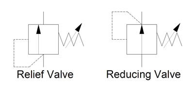
Let’s assume the relief valve is set to 2,000 psi. You’ll have noticed the dashed line coming from the bottom of the symbol, rounding the corner and is attached to the left side. This dashed line indicates the valve is directly operated by the pressure at its inlet port, and that pilot fluid can affect the valve by pushing the arrow to the right. The actual valve has no arrow, of course, but as is the nature of hydraulic symbols, just represents a visual model of what occurs. As pressure in the pilot line approaches 2,000 psi, the arrow is pushed until the valve reaches the centre, allowing fluid to pass, which in turn reduces pressure until upstream is 2,000 psi.
The pressure reducing valve is the only normally open pressure valve in hydraulics. As you can see, it’s very similar to the relief valve, save two changes in the symbol. Firstly, the arrow shows it flows in its neutral position, whereas the relief valve is blocked. Secondly, it gets its pilot signal from downstream of the valve. When downstream pressure rises above the spring setting value, the valve closes, preventing incoming pressure from reaching the downstream path, which allows pressure to decay back to below the pressure setting.
The basics of hydraulic symbology are quite easy, but I’ve only scratched the surface. There are many specialized symbols representing things like electronics, accumulators, various cylinders and ball valves, which I don’t have the room to show. Furthermore, each symbol I’ve shown represents a small portion of the modifications possible to each; there is probably a hundred or more ways to represent a hydraulic pump with a schematic symbol.
Finally, the way in which hydraulic symbols are combined to create a complete schematic representing an actual machine is endless. I recommend you spend time reading hydraulic schematics to interpret the symbols, whenever you have time. Not only will you discover unique symbols, but you’ll come across unique ways to use old symbols and components in a hydraulic circuit.
Below are some common illustrations of equipment located on fluids circuit diagrams, followed by descriptions of the most common elements. Later in this article series we will describe some simple hydraulic and pneumatic circuits composed of these circuit elements.
Needle valves are used to throttle or shut-off flow of fluids. They usually will vary flow with pressure or viscosity change. Some valves can be pressure and/or temperature compensating.
Flow control valves are used to control oil flow in one direction and unrestricted in the opposite direction. "Metered in" control means that the flow controls are controlling the fluid into the actuator, "metered out" is controlling the fluid out of the actuator. Some valves can be pressure and/or temperature compensating.
When the pilot line to a pilot-operated check valve is not pressurized, flow is allowed in one direction but blocked in the opposite direction. When the pilot line in a pilot-to-open valve is pressurized, the check valve is open, allowing flow in either direction.
When the pilot line to a pilot-operated check valve is not pressurized, flow is allowed in one direction but blocked in the opposite direction. When the pilot line in a pilot-to-close valve is pressurized, the check valve is closed, blocking flow in both directions.
Counterbalance valves are used to control overrunning loads and to support loads should a function be stopped at any point throughout its travel. NOTE: this valve is typically preset and should not be tampered with.
Flow fuses are normally open valves which close if the pressure difference between the inlet and outlet valves is too high compared to the design setting. The valve can be reset by reversing the direction of flow. When placed inline with an actuator (for example, a cylinder), flow fuses limit the maximum speed of that actuator.
Directional control valves are used to direct fluid flow into the appropriate lines for the designated operation. These valves are usually electrically controlled.
Hydraulic pumps are used to pump oil from the power unit to other parts of the hydraulic system. Some pumps have control options such as pressure or flow compensators.
Water modulating valves are used for controlling the oil temperature in the reservoir automatically by controlling the volume of water going through the heat exchanger.
Heat exchangers are used to remove heat from the circulating oil in the hydraulic system. The most common heat exchanger is water-to-oil but some times air-to-oil units are used. Coolers will cool the fluid.
Proportional valves are electrically controlled hydraulic valves. These valves proportionally control the hydraulic pressure and/or flow based on an electrical input signal.
For more information about reading hydraulic and pneumatic circuit diagrams, read the next article in this series which describes sample hydraulic circuits, or contact your Valmet representative.
![]()
Hydraulics engineers regularly encounter these diagrams, but these symbols can be daunting to interpret if you have limited experience with schematics and the fluid power industry.
On this page, Carr Lane ROEMHELD provides a comprehensive table outlining the definitions of each symbol used in a hydraulic diagram. Engineers can use this page as a reference to determine common schematic symbols used in fluid power, hydraulics, pneumatics, diagrams and circuits.

The primary purpose of a pressure relief valve is to protect life, property and the environment. Pressure relief valves are designed to open and release excess pressure from vessels or equipment and then close again.
The function of pressure relief valves differs depending on the main type or loading principle of the valve. The main types of pressure relief valves are spring-loaded, weight-loaded and controlled pressure relief valves.
Regardless of the type or load, pressure relief valves are set to a specific set pressure at which the medium is discharged in a controlled manner, thus preventing overpressure of the equipment. In dependence of several parameters such as the contained medium, the set pressure is individual for each safety application.
Engineers use control valve symbols to identify the type of control valve they want to specify for a given application. In this article, we will identify the most commonly used control valve symbols.
The control valve symbols on a P&ID differ depending on the type of valve specified for the application. Each P&ID has its own legend that identifies the symbols for the various equipment.
An engineer may also include specific details below the control valve symbol. These details may include the size, function, pressure rating, and connection type of the valve.
Logic valves can be difficult to understand. We even seem to have trouble agreeing on what to call them. Many people describe them as “cartridge” valves. This is not incorrect, as they are in fact cartridge-type valves. Even the manufacturers typically call them this. I have also heard them referred to as “poppet” valves. Again, this is not incorrect.
They do make a full-beveled seat that allows no bypassing, so they definitely can be classified in this manner. However, I prefer “logic” valves, because “cartridge” does not distinguish them from other cartridge-type valves, such as a relief valve or flow control mounted in a manifold.
Likewise, “poppet” does not differentiate them from other types of poppet valves. Whatever you prefer to call them, they are becoming increasingly popular, so it’s important to understand them as hydraulic systems evolve.
Logic valves have distinct advantages, primarily because they are mounted in a manifold. This enables them to cope with high pressures better than conventional hydraulic plumbing. Over time, hydraulic systems are being operated at higher and higher pressures.
This might explain why so many European machines have used these valves for decades, as historically energy costs have been higher in Europe than in the United States. As U.S. plants begin to be more conscious of energy costs, more American-made machines are using logic valves.
Because the valves are mounted in a manifold, less plumbing is required, so the installation costs are lower. Manifolds can be assembled before a unit is shipped. Installation then becomes more a matter of plumbing large manifolds together than installing individual valves.
Therefore, it’s more important than ever to understand how to read and use a hydraulic schematic as a troubleshooting tool. Unless you have X-ray eyes like Superman, you must rely on a schematic to understand the hydraulic flow.
Logic valves are very versatile. They can emulate almost any type of hydraulic valve and can be used as directional controls, pressure controls, check valves and flow controls. The valves can also handle large amounts of flow with accuracy. Their design may be simple or complex, although generally they are quite simple. While their schematic symbols may take some getting used to, they represent their function very well.
The dotted line to the top surface area indicates a pilot line. At 3 square inches, the pilot surface is the largest of the surface areas. This ensures the pilot side always generates the most force whenever the same pressure is applied to either the bottom or side as is applied to the top. This is a pilot-to-close logic valve. A pilot-to-open logic valve is also available, but it is not used as often.
The most important thing to understand about pilot-to-close logic valves is that if pilot pressure is applied, the valve will stay closed. When no pilot pressure is applied, the valve can be opened with only the pressure required to compress the spring.
This will be a very low pressure. The purpose of the spring is to hold the valve closed whenever there is no pressure in the system. Typically, this pressure will be very low (1-5 bar or 15-75 pounds per square inch), depending on which surface area is used to open the valve. Usually, either a small directional valve or pressure control is employed to pilot the logic valve.
A logic valve is often used as a pressure control when it is necessary to control pressure while handling a large amount of flow. This makes sense, as it is easier and less expensive to manufacture a small precision spring than a large one. In Figure 3, a small pilot relief valve is utilized to limit the pressure from a large amount of flow through a logic valve.
When it is desired that fluid only travel in one direction, a logic valve can be used as a check valve, as shown in Figure 4. If the flow is moving to the right, the logic valve opens once the spring tension is overcome, but any flow to the left will be blocked as pressure is applied to the pilot surface area.
In Figure 5, a logic valve is shown with a mechanical variable actuator symbol. This symbol means there is a screw that can be adjusted to limit how far the logic valve can be opened, thus causing the valve to behave not only as a directional control but also as a flow control.
The variations that can be applied are infinite, allowing logic valves to emulate almost any type of directional, pressure or flow control. The important thing to understand is that the operation of the logic valve is solely dependent on its surface areas.
Logic valves are built to exacting tolerances. The internal clearances are rarely more than a few ten-thousandths of an inch. It generally is recommended that any type of valve be installed with a torque wrench, but for a logic valve, torque settings are critical.
Most of these valves are mounted beneath a cover that is secured by four Allen bolts, as shown in Figure 6. If the bolts are not evenly torqued, the logic valve may not work from the time it is installed.
By far the most common failure of a logic valve is due to contamination, either by particles being introduced to the manifold or generated by component wear and overheating of the fluid.
When several of these valves are mounted in a manifold, they tend to contaminate each other. While the system fluid may be changed and the system flushed, usually the pilot fluid is the same as that which was added at startup. It often never leaves the manifold.
To avoid chasing contaminants through a large manifold, you should flush the manifold when a logic valve is replaced. Many companies have suffered from contaminants moving throughout their manifolds, causing one logic valve failure after another.
Common sense tells us that all the valves in a manifold are under similar stress at similar pressures, have the same fluid traveling between them and are not mounted very far apart. Therefore, if one valve becomes contaminated, the rest of them cannot be far behind.
Jack Weeks is a hydraulic instructor and consultant for GPM Hydraulic Consulting. Since 1997 he has trained thousands of electricians and mechanics in hydraulic troubleshooting methods. Jack has...

Check valves are a simple but important part of a hydraulic system. Simply stated, these valves are used to maintain the direction that fluid flows through a system. And since check valves are zero leakage devices, we can use them to lock hydraulic fluid from the cylinders. This section has been designed to help you understand how the different valves function and the strategy of where they are used in the system.
In-line check valves are classified as directional control valves because they dictate the direction flow can travel in a portion of the circuit. Because of their sealing capability many designs are considered to have zero leakage. The simplest check valve allows free flow in one direction and blocks flow from the opposite direction. This style of check valve is used when flow needs to bypass a pressure valve during return flow, as a bypass around a filter when a filter becomes clogged, or to keep flow from entering a portion of a circuit at an undesirable time.
Because of slight spool leakage on standard directional control valves, we must add a check valve to the circuit if we need to hydraulically lock a cylinder. This type of check valve is referred to as a pilot operated check valve.
Unlike a simple check valve, reverse flow is required through the valve to extend or retract the cylinder. This is accomplished by allowing pilot pressure to act on a pilot piston, thus opening the check valve and retracting the cylinder. To extend the cylinder, the check valve allows fluid to flow freely in one direction and blocks flow in the opposite direction.
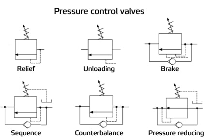
Pressure Control Valves – A control valve is a valve used to control fluid flow by varying the size of the flow passage as directed by a signal from a controller. This enables the direct control of flow rate and the consequential control of process quantities such as pressure, temperature, and liquid level. Common schematics for pressure control valves:
By symbol, these valves closely resemble one another. Often only their location in the hydraulic circuit will designate what type of pressure valve they are.
A sequence valve is a normally closed pressure control valve that ensures that one operation will occur before another, based on pressure. In our clamp and drill system we want the clamp cylinder to extend completely before the drill cylinder extends. To accomplish this, we place a sequence valve just before the drill cylinder. We set the cylinder to 500 psi. This will ensure that the drill will not extend before we have reached 500 psi on the clamp cylinder.
A pressure reducing valve is a normally open pressure control valve used to limit pressure in one or more legs of a hydraulic circuit. Reduced pressure results in a reduced force being generated. A pressure reducing valve is the only pressure control valve that is normally open. A normally open pressure control valve has primary and secondary passages connected. Pressure at the bottom of the spool is sensed from the pilot line which is connected to the secondary port. Remember, a pressure reducing valve is normally open.
The illustrated clamp circuit requires that clamp cylinder B apply a lesser force than clamp cylinder A. A pressure reducing valve placed just before the clamp cylinder B will allow flow to go to the cylinder until pressure reaches the setting of the valve.
At this point, the valve begins to close off, limiting any further buildup of pressure. As fluid bleeds to the tank through the valve drain passage, pressure will begin to decay off and the valve will again open. The result is a reduced modulated pressure equal to the setting of the valve.
An unloading valve is a remotely piloted, normally closed pressure control valve that directs flow to the tank when pressure at that location reaches a predetermined level. A good example of an unloading valve application would be a High-Low system. A High-Low system may consist of two pumps; one high volume pump, the other a low volume pump. The system is designed to give a rapid approach or return on the work cylinder. The total volume of both pumps is delivered to the work cylinder until the load is contacted.
At this point the system pressure increases, causing the unloading valve to open. The flow from the large volume pump is directed back to the tank at a minimal pressure. The small volume pump continues to deliver flow for the higher-pressure requirement of the work cycle. Both pumps join again for rapid return of the cylinder. This application allows less input horsepower for speed and force requirements
The purpose of a counterbalance valve is to prevent a loaded cylinder, having potential energy, from falling (extending or retracting). Counterbalance valves may be internally piloted, externally piloted, or piloted internally as well as externally, and they may be internally or externally drained. If conditions exist that would interfere with internal draining the valve, it should be externally drained, but usually this is not necessary. Counterbalance valves are equipped with a free reverse flow check valve to allow for retraction of the cylinder.
The simplest counterbalance valve application is to support a constant induced load. In a down acting press application, the counterbalance valve would be installed at the rod end of the cylinder to control return oil flow. This would prevent the press platen from dropping. Pilot pressure to open an internally piloted counterbalance valve would be set approximately 100 psi above the pressure of the rod end of the cylinder caused by the weight of the platen. In order for the platen to be lowered (and powered down), the pressure at the cap end of the cylinder would have to be sufficient to generate 100 additional psi at the rod end of the cylinder. Thus, 100 psi added to the pressure generated by the weight of the platen would open the counterbalance valve and allow the platen to lower smoothly.
One disadvantage of the counterbalance valve shown in the circuit in Figure 1-13 is that back pressure on the cap side of the cylinder limits the effective force developed by the cylinder. In order to achieve full force from the cylinder, the back pressure must be relieved from the cap side of the cylinder.
This is easily achieved by using a counterbalance valve that includes an external pilot. Counterbalance valves that include an external pilot in addition to the internal pilot are called holding valves, over center valves, load control valves, or motion control valves by some manufacturers. After the cylinder has stalled against the load, the external pilot will fully open the counterbalance valve, allowing the pressure in the cap end of the cylinder to fall to virtually zero psi.
Counterbalance valves may prevent a loaded cylinder from falling. Pilot check valve circuits also hold loaded cylinders in place. Both types of circuits have unique applications. Counterbalance valves may be leak-free. For example, manufacturers commonly give the leakage rates across a counterbalance spool in drops per minute. If a cylinder must be locked in place with a valve that allows no leakage across the spool, the valve must be designed to do so.
Counterbalance valves may also incorporate external piloting for smoother, “non hunting” performance. When the manufacturer utilizes both internal and external pilots you have the best of both worlds. The internal pilot lowers the load with counter pressure, while the external pilot drops all back pressure when performing work.
A counterbalance valve is a normally closed pressure valve used with cylinders to counter a weight or potentially overrunning load. In this circuit, without a counterbalance valve the load would fall uncontrolled or overrun and pump flow would not be able to keep up. To avoid the uncontrolled operation, we place a counterbalance valve just after the cylinder.
The pressure setting of the counterbalance valve is set slightly above the load- induced pressure of 1100 psi. This counters the load. As we extend the cylinder, pressure must slightly rise to drive the load down.
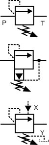
Relief valves are normally closed valves which sense pressure upstream of the pressure relief valve. When the pressure reaches the setting of the valve, the valve opens to relieve the over pressure fluid to the reservoir. Figure 1-9a shows a direct acting, or single stage, relief valve.
The dashed pilot line connected to the valve envelope at the point at which the inlet line meets the envelope indicates the pilot pressure in sensed internally to the body of the valve. The spring chamber in relief valves are internally drained to the outlet, or secondary port, though that feature is not shown by current ISO 1219-1 symbols. Back pressure in the outlet line of a relief valve acts on the spring side of the poppet or spool, and thus is additive to the pressure setting of the valve. What this means is that if the tank line back pressure increases by 100 psi, the valve will open at 100 psi more than it was set to open, though the differential pressure across the valve does not change.
Figure 1-9b shows the simplified symbol for a pilot operated, or two stage, relief valve, while Figure 1-9c shows the detailed symbol for a pilot operated relief valve. Pilot operated relief valves may be remote piloted, sometimes from the operator’s station. The detailed symbol shown includes a vent port connection allowing a second direct acting relief valve to be connected to this port, thus allowing remote control of the main relief valve.
In addition to a remote pilot relief valve, or as an alternative, a solenoid valve may be connected to the main relief valve in order to vent the main relief valve down to low pressure.
Circuits using fixed displacement pumps must have a pressure relief valve. Not all variable volume pumps are pressure compensated. Therefore, these pumps also require relief valves. Many pressure-compensated pumps have compensators that can fail in an “on stroke” condition, therefore requiring a relief valve as well. The main relief valve in a circuit is generally termed the system relief valve. However, relief valves are also used in branch circuits in order to protect an actuator. These circuit relief valves are usually called cross port relief valves when used with a motor and cylinder relief valves when used to protect a cylinder.
Pressure relief, pressure reducing, unloading, sequence, counterbalance, and brake valves control the pressure in systems. One of these valves can serve multiple purposes, depending upon where it is located in the circuit, how it is plumbed, how the pilot circuit operates, and whether or not the valve drains internally into the reservoir return line or has an external drain.
The pressure reducing valve schematic shown in Figure 1-9d (on page 39 above), shows normally open valves used to limit the maximum force of actuators in branch circuits. Pressure reducing valves control the force by sensing the pressure at the secondary (outlet) port of the valve. When downstream pressure reaches the pressure setting of the valve, the spool begins to meter flow into the circuit, limiting the downstream pressure to the pressure setting of the valve. Since pressure is defined as resistance to flow, pressure can be controlled by regulating the flow into the circuit. In a typical application, the pressure reducing valve comes into operation when a cylinder in a branch circuit deadheads against the load resistance. The pressure then rises to the pressure setting of the reducing valve.
By controlling the downstream pressure, the valve limits the maximum output force of the actuator in the branch circuit. Because pressure reducing valves sense pressure at the outlet port, they are externally drained. Obstructing the drain of a pressure reducing valve will prevent the valve from operating from the normally open to the closed position.
Figure 1-9e (on page 39) shows the symbol for a pressure reducing-relieving valve, which in addition to reducing downstream pressure, will relieve downstream pressure.
Unloading valves are used with high-low pump circuits and with accumulator circuits to save power when fixed displacement pumps are used. Some manufacturers market an unloading-relief valve which, in addition to the external pilot that is connected downstream of the check valve, includes an internal pilot connection. This version is shown by the symbol in Figure 1-9f above. The main characteristic of an unloading valve is the external pilot line that allows the valve to sense pressure downstream of the check valve used in applications for unloading valves. Several manufacturers offer the unloading valve and check valve in the same body assembly.
In addition, an unloading valve is a remotely piloted, normally closed pressure control valve that directs flow to the tank when pressure at that location reaches a predetermined level. A good example of an unloading valve application would be a High-Low system. A High-Low system may consist of two pumps; one high volume pump, the other a low volume pump. The system is designed to give a rapid approach or return on the work cylinder. The total volume of both pumps is delivered to the work cylinder until the load is contacted.
In a typical accumulator application, shown in Figure 1-10 below, hydraulic oil from the fixed displacement pump will pass through an isolating check valve to fill the accumulator. This type of circuit uses a 3-position directional control valve that has a blocked pressure port in the center envelope. When the accumulator becomes filled, pressure on the accumulator side of the check valve pilots the unloading valve open, unloading the pump to the reservoir at low pressure.
The unloading valve will remain open as long as the accumulator can supply pilot pressure above the setting of the valve. When the pressure downstream of the check valve drops below the pressure setting of the unloading valve, the unloading valve closes, allowing the pump to refill the accumulator.
The unloading valve shown in Figure 1-10 is a variation on a standard unloading valve as it includes an internal as well as an external pilot, making the valve illustrated an unloading-relief valve. The valve will open upon sensing adequate pilot pressure from either pilot source. There are differential pressure unloading valves which are specifically used in accumulator circuits to open at a higher pressure than they close.
Unloading valves are normally closed, externally piloted, and may be internally or externally drained. An external drain is required if there is back pressure at the outlet port, for example if the fluid is unloaded through a heat exchanger or circuit that creates back pressure that would upset the pressure differential of the valve. An unloading valve has a low pressure drop across the valve when it is in the open state. The valve is held fully open by the pilot signal to unload the pump at low pressure.
Figure 1-11 shows a typical high-low pump circuit. The unloading valve is actuated by rising pressure downstream from the check valve, unloading the high-volume pump at low pressure. When an unloading valve is piloted open by the external pilot, there is a low pressure drop across the valve, as it is being held open by the pilot pressure. If an unloading valve is subject to back pressure, it should be externally drained.
They are used on clamp and work circuits to assure required clamping force is reached in the clamp cylinder before the work portion of the cycle begins. Sequence valves may be internally or externally pilot operated, but they must have an external drain because the outlet port is pressurized. Sequence valves may be equipped with integral reverse free-flow check valves. Sequence valves are normally closed and are pilot operated to open to allow full flow to the actuator. In a typical application, fluid is directed to extend both the clamp and drill cylinders at the same time.
The sequence valve is installed in series with the drill cylinder. The clamp cylinder receives fluid first, with its minimum force determined by the pressure required to open the sequence valve at the drill cylinder, and the area of the clamp cylinder. When the minimum clamping cylinder pressure is reached, the sequence valve opens, and the drill cylinder will advance. The maximum extension force of both cylinders is determined by the pressure setting of the system relief valve, the areas of the cylinders, or by pressure reducing valves, if any are used.
When the directional control valve is reversed to retract the cylinders, some means must be employed to prevent both cylinders from retracting at the same time. This would cause the clamp to relax while the drill was still in the work piece. The proper sequence would be first to retract the drill, and then to retract the clamp.
One method to accomplish the reverse sequence would be to install a second sequence valve at the rod end of the clamp cylinder. This would route flow first to the rod end of the drill cylinder, causing it to retract, followed by the opening of the sequence valve when the pressure rises, allowing flow to the rod side of the clamp cylinder. Both cylinders will now operate in the proper sequence. It should be noticed that the clamp cylinder loses pressure to hold the clamp closed when the directional control valve is shifted to retract both cylinders.
A sequence valve is essentially an externally drained relief valve. As such, it may be used as a relief valve in applications where the back pressure that acts on the tank port of the relief valve varies, causing changes in the opening pressure of the relief valve.
Easy adjustment is done by simply turning the handle clockwise to increase the pressure. The valves offer repeatability accuracy of ±3% and an adjustment range of 800-10,000 psi (55-700 bar).
The maximum oil flow is 1830 in3 /min (30 l/min) and the valve features NPT or SAE porting to insure against leakage at rated pressure. A 3 ft return line hose kit is included.


 8613371530291