
hydraulic safety valve symbol brands
A PVC or polyvinyl chloride ball valve is a plastic on and off valve that has a rotary ball with a bore where turning the ball a quarter turn can stop the flow of a fluid. They are highly durable, cost effective and can be...

The HBH Series valves are redundant blocking valve systems designed for critical applications where safe load holding is required for hydraulically controlled cylinders. These valve systems are equipped with position sensors for external monitoring by an electrical safety control system.
The improper installation of pressure relief devices can have dire consequences, causing unnecessary safety risks, and delaying operations while they are replaced or repaired. PRVs are typically one of the last lines of defense in an upset condition. To ensure that PRVs relieve and flow properly, the ASME and the National Board certify all PRV assembly programs, testing facilities, and even technicians. When you see marks and symbols on your pressure relief devices, it means that your device is certified safe because it came from a National Board and/or ASME certified organization.
The National Board sets the industry standards for pressure relief devices and is responsible for markings and symbols on their pressure relief devices are those that:
The five symbols in the above graphic above are issued by the ASME and National Board. There are others, and you may see a few different variations from time to time. Each of them denotes a specific certification:
The National Board offers the Certificate of Authorization and the “R” symbol stamp for the repair and/or alteration of boilers, pressure vessels, and other pressure-retaining items.
The simple answer? Safety. However, there’s a bit more to safety than you might think. In order to ensure safe operation, organizations like the ASME and National Board set firm standards and require the completion of specific programs to attain certification. These programs are rigorous, and the UV Assembly Program is no exception. It’s designed to be very stringent, as it ensures consistency in the capabilities and functionality of all components in the PRV assembly process. Ideally, a PRV should be procured from a certified assembler that is also able to test and repair the device if necessary. Unfortunately, this is a tall order that not all suppliers are able to.
Vinson Process Controls has the capabilities and credentials required to assemble, test and repair pressure relief devices. In order to better serve our customers, we earned the certifications for the UV (assembly program), VR (valve repair) and T/O (testing only) certifications from the ASME and the National Board. We take the guesswork out of PRV procuring and maintenance so that our customers can relax and reap the benefits.
As a UV-certified assembler, Vinson has invested in stocking Anderson Greenwood™ and Crosby™ relief valves for faster lead times. We have a wide range of options for our customers, including same-day service, when required. The vast majority of Vinson’s relief valve inventory is in the portable 81P valves and pilot operated valves. Apart from the combined inventory we share with Emerson, we also have access to shared inventory across all 21 of Emerson’s Impact Partners. We are proud to say that all valves assembled in our Carrolton Valve Center have met or exceeded expected shipping dates.
In addition to faster lead times, our customers can maintain confidence that the products shipping from Vinson are of the samequality as those shipping directly from Emerson’s factory. The ASME, the National Board and Emerson audit all shops, quality control processes, techniques, and valves, before and after awarding certifications. Vinson will continue to receive audits to ensure that we are meeting or exceeding expectations over time. Our adhesion to our quality control manual means that all valves assembled by Vinson have the same factory warranty as if they were assembled in Emerson’s production line.
As a part of the Emerson Impact Partner Network, Vinson is one of the primary points of contact for direct sales of Anderson Greenwood™ and Crosby™. We are a certified UV assembler, also offering valve repair and testing services. We can offer you quotes for both repair and replacement options. Because of this unique status, Vinson can offer competitive pricing.

Valves are mechanical devices that control the flow and pressure of a fluid in a hydraulic or air system. They are essential components of pipe systems that transport liquids, gases, vapors, sludge, etc.
There are many different types of valves are available, each one has different characteristics, capacity and uses. There are different operation methods available: manual, pneumatic, electric, etc.
The BERMAD Hydraulic Control Valve is a hydraulically operated, diaphragm actuated control valve that opens and shuts in response to a local or remote pressure command.
... reducing control valve that reduces a high upstream pressure to a lower constant downstream pressure, regardless of fluctuating demand or varying upstream pressure. BERMAD 700 series valves are hydraulic, ...
... BERMAD 700 SIGMA EN/ES series valves are hydraulic, oblique pattern, globe valves with a raised seat assembly and double chamber unitized actuator, that can be disassembled from the body ...
... and corrosion resistance, the Isogate® WB series heavy duty slurry knife gate valve combines a low maintenance design with a wide range of available materials making the valve suitable for a variety of ...
Pre-load valves, also called sequence valves are a type of pressure control valve. They generate a largely constant pressure drop between the inlet and outlet on the valve. ...
Proportional pressure-reducing valves are a type of pressure control valve. They remotely control the pressure in hydraulic systems continually and electrically.
Pressure reducing valves type ADC and AM are suitable for the supply of control circuits with low oil consumption. These valves feature an override compensation, i.e. acting like a pressure-limiting valve ...
Triple-offset butterfly valve, metal-seated (fire-safe), without gland packing, maintenance-free, with lever or manual gearbox, pneumatic, electric or hydraulic actuator. Body made of ...
Get the most out of hydraulic systems with pneumatic in-line, three-way Airflex Quick Release Valves (QRVs) from Eaton. Engineered to automatically close upon pressurization and open when a pressure drop ...
... refrigerantleaks. The valve should as a rule be installed asillustrated in fig. 1.In order to prevent hydraulic pressure buildingup between the stop valve and the QDV anintegral relief ...
... Rotork manPOWER range high-integrity failsafe valve operation without the need for any power supply. The self-contained system is suitable for workshop or mounting on a wide range of rotary and linear operated valves ...
The Fisher 8560 Butterfly valve is a reliable, high performance control valve suitable for throttling applications requiring extremely low leakage rates.
This high pressure miniature pressure compensating flow control valve is only .250” in diameter and 1.38” in length. This valve provides a constant flow rate over a wide range of pressure differentials. ...
The Lee Company’s dual metering flow control valves are 2-way restrictors that allow a designer to specify a different metered flow rate in each direction. These valves are ideal for high-pressure hydraulic ...
... miniature valve has a maximum restriction of 70 Lohms when fully open and weighs only 16 grams. The metal components are constructed entirely of stainless steel for durability and long life. Similar to Lee Shuttle Valves, ...
The KPES6 is a compact valve for levelling control of attachments on agricultural vehicles. It provides priority flow supply to A and b ports (for levelling) and pressure compensation for A, B and N ports (for hitch control).
Our sister company in Sweden Stafsjö Valves develop and manufacture high performance shut-off valves for pulp lines in pulp and paper mills, mineral processing and tailing systems in the mining industry, ...
Our sister company in Sweden Stafsjö Valves develop and manufacture high performance shut-off valves for pulp lines in pulp and paper mills, mineral processing and tailing systems in the mining industry, ...
Our sister company in Sweden Stafsjö Valves develop and manufacture high performance shut-off valves for pulp lines in pulp and paper mills, mineral processing and tailing systems in the mining industry, ...
Centred-disc butterfly valve, sealed by elastomer liner, with lever or manual gearbox, pneumatic, electric or hydraulic actuator. Wafer-type body (T1), semi-lug body (T2), full-lug body ...
Flow divider valves are self-regulating devices, that largely independent of the difference in pressure at the working ports A and B split an input flow QC entering at port C into two equal output flows QA and QB or maintain ...
W60 series single seat valves are used to shut-off or divert flow in a process system. These valves are pneumatically or manually operated, and offered in a wide variety of configurations. These valves ...
Unloading Valves, Hydraulically ControlledDescriptionSeries DWPB-4N… cartridges are size 4, two stage, high performance pressure-unloading valves with an 3/4-16 UNF mounting thread. They consist of a ...
Cylinder body made of steel, phosphatized. Remaining parts made of tempering steel. Valve seat and piston are hardened and ground. This valve is leak free.
... design. Unlike valve seats with metallic sealing, the TVR400 valves have a soft seal. They are sealed by means of a spring-loaded sealing cone with an O-ring. The WEH® valves therefore ...
Hydraulic symbols provide a clear representation of the function of each hydraulic component. Laying each symbol out on the page in the same sequence the components are used in the circuit allows people to understand the complete function of the hydraulic equipment.
Poppet, one-way, shuttle, or check valves are shown as a ball sitting on a seat. Pass flow through the seat and the valve opens. Pass flow from the ball side and the valve will close.
Poppet or check valves have a physical seat that the valve presses against. This positive connection may exhibit zero, or more likely a very small leakage across it.
In many cases, these are the cheapest and most simple valves but they also have the potential to be the largest, most complicated, expensive, and difficult to control.
Most hydraulic components are controlled when pressure is applied to one side of a piston or another. In the case of cylinders, the force generated by the piston will move and drive the load. In the case of a directional valve, the force is used to move a spool which opens different passageways to allow the fluid to flow along different pipelines.
Spool valves rely on tiny clearances to allow them to move freely. These spool clearances are small enough to hold the pressure but still large enough to allow a small amount of fluid to leak past. Cylinder pistons include seals which will exhibit much smaller leakages.
An orifice is just a small hole, either fixed or adjustable. With increasing flow across an orifice there will also an increasing pressure drop across it, this pressure is commonly used to open or close other spool valves or poppets. Alternately if a system has a specific set pressure then the orifice might be used to control the flow rate along its pipework.
Squares and rectangles form the basis of pressure and directional control valves. A single box for pressure control and multiple boxes for directional control.
The valve sits between a hose and a cylinder. It is drawn as a two-position valve with an adjustable orifice in one position and a one-way check valve in the other. A spring holds it in one position but there are pressure feed pilot lines (dotted lines) feeding each end of the valve from opposite ports on the valve. This means that at low speeds while lowering and always while raising the cylinder, the valve stays open. However, if the hose was to break the cylinder started dropping quickly, the pressure difference across the orifice would cause the valve to switch, such that the check valve would block the pipeline. This would stop the cylinder from falling further. Therefore this is a hose burse safety protection valve.
The check valve is used to isolate the pump from backflows from the circuit, it also helps to keep the pump primed if components are removed. As the orifice size is reduced the pressure upsteam of the orifice will increase. The pressure is also sensed on one end of the directional valve (along dotted line) which will push the valve spool against the spring and therefore vent the circuit, maintaining a constant pressure on the pump.
Hydraulic circuits can be comprised of an infinite combination of cylinders, motors, valves, pumps and other equipment connected via hydraulic pipes and tubes. The complexity of these components are difficult to represent fully, so a family of graphic symbols have been developed to represent fluid power components and systems on schematic drawings.
The symbols do not identify component size or their actual position on the machine, however the symbols do provide vital information relating to the configurations and flow path connections.
Below we have summarised some of the most common symbols you may come across. Our technical sales engineers will be happy to help should you need any further help and assistance. Please get in touch on +44 (0)845-644-3640.
If you are looking for a supplier who makes quality hydraulic products suitable for just about every industry, you"ve found them in Brand Hydraulics. Their electronic controls, flow controls, hydraulic relief valves, check and shuttle valves are made in the American Heartland, but used worldwide. Brand Hydraulics products span demanding applications, from agriculture and forestry to marine, entertainment and transportation industries. Brand is dedicated to innovation and creating new products geared to meeting their customers" specific needs. Demand Brand!
Check valves are a simple but important part of a hydraulic system. Simply stated, these valves are used to maintain the direction that fluid flows through a system. And since check valves are zero leakage devices, we can use them to lock hydraulic fluid from the cylinders. This section has been designed to help you understand how the different valves function and the strategy of where they are used in the system.
In-line check valves are classified as directional control valves because they dictate the direction flow can travel in a portion of the circuit. Because of their sealing capability many designs are considered to have zero leakage. The simplest check valve allows free flow in one direction and blocks flow from the opposite direction. This style of check valve is used when flow needs to bypass a pressure valve during return flow, as a bypass around a filter when a filter becomes clogged, or to keep flow from entering a portion of a circuit at an undesirable time.
Because of slight spool leakage on standard directional control valves, we must add a check valve to the circuit if we need to hydraulically lock a cylinder. This type of check valve is referred to as a pilot operated check valve.
Unlike a simple check valve, reverse flow is required through the valve to extend or retract the cylinder. This is accomplished by allowing pilot pressure to act on a pilot piston, thus opening the check valve and retracting the cylinder. To extend the cylinder, the check valve allows fluid to flow freely in one direction and blocks flow in the opposite direction.
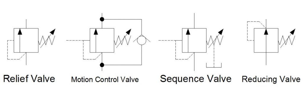
Pressure Control Valves – A control valve is a valve used to control fluid flow by varying the size of the flow passage as directed by a signal from a controller. This enables the direct control of flow rate and the consequential control of process quantities such as pressure, temperature, and liquid level. Common schematics for pressure control valves:
By symbol, these valves closely resemble one another. Often only their location in the hydraulic circuit will designate what type of pressure valve they are.
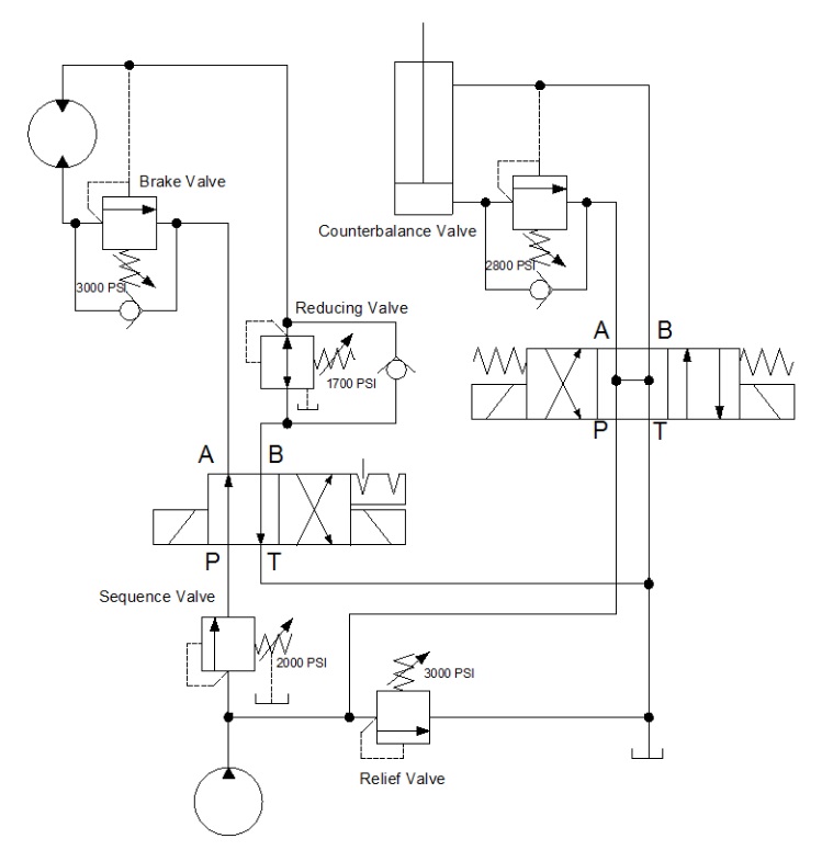
A sequence valve is a normally closed pressure control valve that ensures that one operation will occur before another, based on pressure. In our clamp and drill system we want the clamp cylinder to extend completely before the drill cylinder extends. To accomplish this, we place a sequence valve just before the drill cylinder. We set the cylinder to 500 psi. This will ensure that the drill will not extend before we have reached 500 psi on the clamp cylinder.
A pressure reducing valve is a normally open pressure control valve used to limit pressure in one or more legs of a hydraulic circuit. Reduced pressure results in a reduced force being generated. A pressure reducing valve is the only pressure control valve that is normally open. A normally open pressure control valve has primary and secondary passages connected. Pressure at the bottom of the spool is sensed from the pilot line which is connected to the secondary port. Remember, a pressure reducing valve is normally open.
The illustrated clamp circuit requires that clamp cylinder B apply a lesser force than clamp cylinder A. A pressure reducing valve placed just before the clamp cylinder B will allow flow to go to the cylinder until pressure reaches the setting of the valve.
At this point, the valve begins to close off, limiting any further buildup of pressure. As fluid bleeds to the tank through the valve drain passage, pressure will begin to decay off and the valve will again open. The result is a reduced modulated pressure equal to the setting of the valve.
An unloading valve is a remotely piloted, normally closed pressure control valve that directs flow to the tank when pressure at that location reaches a predetermined level. A good example of an unloading valve application would be a High-Low system. A High-Low system may consist of two pumps; one high volume pump, the other a low volume pump. The system is designed to give a rapid approach or return on the work cylinder. The total volume of both pumps is delivered to the work cylinder until the load is contacted.
At this point the system pressure increases, causing the unloading valve to open. The flow from the large volume pump is directed back to the tank at a minimal pressure. The small volume pump continues to deliver flow for the higher-pressure requirement of the work cycle. Both pumps join again for rapid return of the cylinder. This application allows less input horsepower for speed and force requirements
The purpose of a counterbalance valve is to prevent a loaded cylinder, having potential energy, from falling (extending or retracting). Counterbalance valves may be internally piloted, externally piloted, or piloted internally as well as externally, and they may be internally or externally drained. If conditions exist that would interfere with internal draining the valve, it should be externally drained, but usually this is not necessary. Counterbalance valves are equipped with a free reverse flow check valve to allow for retraction of the cylinder.
The simplest counterbalance valve application is to support a constant induced load. In a down acting press application, the counterbalance valve would be installed at the rod end of the cylinder to control return oil flow. This would prevent the press platen from dropping. Pilot pressure to open an internally piloted counterbalance valve would be set approximately 100 psi above the pressure of the rod end of the cylinder caused by the weight of the platen. In order for the platen to be lowered (and powered down), the pressure at the cap end of the cylinder would have to be sufficient to generate 100 additional psi at the rod end of the cylinder. Thus, 100 psi added to the pressure generated by the weight of the platen would open the counterbalance valve and allow the platen to lower smoothly.
One disadvantage of the counterbalance valve shown in the circuit in Figure 1-13 is that back pressure on the cap side of the cylinder limits the effective force developed by the cylinder. In order to achieve full force from the cylinder, the back pressure must be relieved from the cap side of the cylinder.
This is easily achieved by using a counterbalance valve that includes an external pilot. Counterbalance valves that include an external pilot in addition to the internal pilot are called holding valves, over center valves, load control valves, or motion control valves by some manufacturers. After the cylinder has stalled against the load, the external pilot will fully open the counterbalance valve, allowing the pressure in the cap end of the cylinder to fall to virtually zero psi.
Counterbalance valves may prevent a loaded cylinder from falling. Pilot check valve circuits also hold loaded cylinders in place. Both types of circuits have unique applications. Counterbalance valves may be leak-free. For example, manufacturers commonly give the leakage rates across a counterbalance spool in drops per minute. If a cylinder must be locked in place with a valve that allows no leakage across the spool, the valve must be designed to do so.
Counterbalance valves may also incorporate external piloting for smoother, “non hunting” performance. When the manufacturer utilizes both internal and external pilots you have the best of both worlds. The internal pilot lowers the load with counter pressure, while the external pilot drops all back pressure when performing work.
A counterbalance valve is a normally closed pressure valve used with cylinders to counter a weight or potentially overrunning load. In this circuit, without a counterbalance valve the load would fall uncontrolled or overrun and pump flow would not be able to keep up. To avoid the uncontrolled operation, we place a counterbalance valve just after the cylinder.
The pressure setting of the counterbalance valve is set slightly above the load- induced pressure of 1100 psi. This counters the load. As we extend the cylinder, pressure must slightly rise to drive the load down.
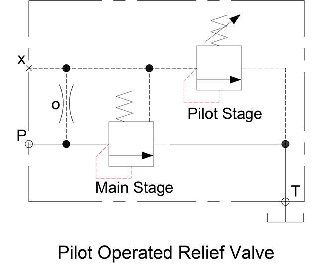
Relief valves are normally closed valves which sense pressure upstream of the pressure relief valve. When the pressure reaches the setting of the valve, the valve opens to relieve the over pressure fluid to the reservoir. Figure 1-9a shows a direct acting, or single stage, relief valve.
The dashed pilot line connected to the valve envelope at the point at which the inlet line meets the envelope indicates the pilot pressure in sensed internally to the body of the valve. The spring chamber in relief valves are internally drained to the outlet, or secondary port, though that feature is not shown by current ISO 1219-1 symbols. Back pressure in the outlet line of a relief valve acts on the spring side of the poppet or spool, and thus is additive to the pressure setting of the valve. What this means is that if the tank line back pressure increases by 100 psi, the valve will open at 100 psi more than it was set to open, though the differential pressure across the valve does not change.
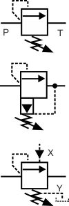
Figure 1-9b shows the simplified symbol for a pilot operated, or two stage, relief valve, while Figure 1-9c shows the detailed symbol for a pilot operated relief valve. Pilot operated relief valves may be remote piloted, sometimes from the operator’s station. The detailed symbol shown includes a vent port connection allowing a second direct acting relief valve to be connected to this port, thus allowing remote control of the main relief valve.
In addition to a remote pilot relief valve, or as an alternative, a solenoid valve may be connected to the main relief valve in order to vent the main relief valve down to low pressure.
Circuits using fixed displacement pumps must have a pressure relief valve. Not all variable volume pumps are pressure compensated. Therefore, these pumps also require relief valves. Many pressure-compensated pumps have compensators that can fail in an “on stroke” condition, therefore requiring a relief valve as well. The main relief valve in a circuit is generally termed the system relief valve. However, relief valves are also used in branch circuits in order to protect an actuator. These circuit relief valves are usually called cross port relief valves when used with a motor and cylinder relief valves when used to protect a cylinder.
Pressure relief, pressure reducing, unloading, sequence, counterbalance, and brake valves control the pressure in systems. One of these valves can serve multiple purposes, depending upon where it is located in the circuit, how it is plumbed, how the pilot circuit operates, and whether or not the valve drains internally into the reservoir return line or has an external drain.
The pressure reducing valve schematic shown in Figure 1-9d (on page 39 above), shows normally open valves used to limit the maximum force of actuators in branch circuits. Pressure reducing valves control the force by sensing the pressure at the secondary (outlet) port of the valve. When downstream pressure reaches the pressure setting of the valve, the spool begins to meter flow into the circuit, limiting the downstream pressure to the pressure setting of the valve. Since pressure is defined as resistance to flow, pressure can be controlled by regulating the flow into the circuit. In a typical application, the pressure reducing valve comes into operation when a cylinder in a branch circuit deadheads against the load resistance. The pressure then rises to the pressure setting of the reducing valve.
By controlling the downstream pressure, the valve limits the maximum output force of the actuator in the branch circuit. Because pressure reducing valves sense pressure at the outlet port, they are externally drained. Obstructing the drain of a pressure reducing valve will prevent the valve from operating from the normally open to the closed position.
Figure 1-9e (on page 39) shows the symbol for a pressure reducing-relieving valve, which in addition to reducing downstream pressure, will relieve downstream pressure.
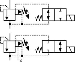
Unloading valves are used with high-low pump circuits and with accumulator circuits to save power when fixed displacement pumps are used. Some manufacturers market an unloading-relief valve which, in addition to the external pilot that is connected downstream of the check valve, includes an internal pilot connection. This version is shown by the symbol in Figure 1-9f above. The main characteristic of an unloading valve is the external pilot line that allows the valve to sense pressure downstream of the check valve used in applications for unloading valves. Several manufacturers offer the unloading valve and check valve in the same body assembly.
In addition, an unloading valve is a remotely piloted, normally closed pressure control valve that directs flow to the tank when pressure at that location reaches a predetermined level. A good example of an unloading valve application would be a High-Low system. A High-Low system may consist of two pumps; one high volume pump, the other a low volume pump. The system is designed to give a rapid approach or return on the work cylinder. The total volume of both pumps is delivered to the work cylinder until the load is contacted.
In a typical accumulator application, shown in Figure 1-10 below, hydraulic oil from the fixed displacement pump will pass through an isolating check valve to fill the accumulator. This type of circuit uses a 3-position directional control valve that has a blocked pressure port in the center envelope. When the accumulator becomes filled, pressure on the accumulator side of the check valve pilots the unloading valve open, unloading the pump to the reservoir at low pressure.
The unloading valve will remain open as long as the accumulator can supply pilot pressure above the setting of the valve. When the pressure downstream of the check valve drops below the pressure setting of the unloading valve, the unloading valve closes, allowing the pump to refill the accumulator.
The unloading valve shown in Figure 1-10 is a variation on a standard unloading valve as it includes an internal as well as an external pilot, making the valve illustrated an unloading-relief valve. The valve will open upon sensing adequate pilot pressure from either pilot source. There are differential pressure unloading valves which are specifically used in accumulator circuits to open at a higher pressure than they close.
Unloading valves are normally closed, externally piloted, and may be internally or externally drained. An external drain is required if there is back pressure at the outlet port, for example if the fluid is unloaded through a heat exchanger or circuit that creates back pressure that would upset the pressure differential of the valve. An unloading valve has a low pressure drop across the valve when it is in the open state. The valve is held fully open by the pilot signal to unload the pump at low pressure.
Figure 1-11 shows a typical high-low pump circuit. The unloading valve is actuated by rising pressure downstream from the check valve, unloading the high-volume pump at low pressure. When an unloading valve is piloted open by the external pilot, there is a low pressure drop across the valve, as it is being held open by the pilot pressure. If an unloading valve is subject to back pressure, it should be externally drained.
They are used on clamp and work circuits to assure required clamping force is reached in the clamp cylinder before the work portion of the cycle begins. Sequence valves may be internally or externally pilot operated, but they must have an external drain because the outlet port is pressurized. Sequence valves may be equipped with integral reverse free-flow check valves. Sequence valves are normally closed and are pilot operated to open to allow full flow to the actuator. In a typical application, fluid is directed to extend both the clamp and drill cylinders at the same time.
The sequence valve is installed in series with the drill cylinder. The clamp cylinder receives fluid first, with its minimum force determined by the pressure required to open the sequence valve at the drill cylinder, and the area of the clamp cylinder. When the minimum clamping cylinder pressure is reached, the sequence valve opens, and the drill cylinder will advance. The maximum extension force of both cylinders is determined by the pressure setting of the system relief valve, the areas of the cylinders, or by pressure reducing valves, if any are used.
When the directional control valve is reversed to retract the cylinders, some means must be employed to prevent both cylinders from retracting at the same time. This would cause the clamp to relax while the drill was still in the work piece. The proper sequence would be first to retract the drill, and then to retract the clamp.
One method to accomplish the reverse sequence would be to install a second sequence valve at the rod end of the clamp cylinder. This would route flow first to the rod end of the drill cylinder, causing it to retract, followed by the opening of the sequence valve when the pressure rises, allowing flow to the rod side of the clamp cylinder. Both cylinders will now operate in the proper sequence. It should be noticed that the clamp cylinder loses pressure to hold the clamp closed when the directional control valve is shifted to retract both cylinders.
A sequence valve is essentially an externally drained relief valve. As such, it may be used as a relief valve in applications where the back pressure that acts on the tank port of the relief valve varies, causing changes in the opening pressure of the relief valve.

Below are some common illustrations of equipment located on fluids circuit diagrams, followed by descriptions of the most common elements. Later in this article series we will describe some simple hydraulic and pneumatic circuits composed of these circuit elements.
Needle valves are used to throttle or shut-off flow of fluids. They usually will vary flow with pressure or viscosity change. Some valves can be pressure and/or temperature compensating.
Flow control valves are used to control oil flow in one direction and unrestricted in the opposite direction. "Metered in" control means that the flow controls are controlling the fluid into the actuator, "metered out" is controlling the fluid out of the actuator. Some valves can be pressure and/or temperature compensating.
When the pilot line to a pilot-operated check valve is not pressurized, flow is allowed in one direction but blocked in the opposite direction. When the pilot line in a pilot-to-open valve is pressurized, the check valve is open, allowing flow in either direction.
When the pilot line to a pilot-operated check valve is not pressurized, flow is allowed in one direction but blocked in the opposite direction. When the pilot line in a pilot-to-close valve is pressurized, the check valve is closed, blocking flow in both directions.
Counterbalance valves are used to control overrunning loads and to support loads should a function be stopped at any point throughout its travel. NOTE: this valve is typically preset and should not be tampered with.
Flow fuses are normally open valves which close if the pressure difference between the inlet and outlet valves is too high compared to the design setting. The valve can be reset by reversing the direction of flow. When placed inline with an actuator (for example, a cylinder), flow fuses limit the maximum speed of that actuator.
Directional control valves are used to direct fluid flow into the appropriate lines for the designated operation. These valves are usually electrically controlled.
Hydraulic pumps are used to pump oil from the power unit to other parts of the hydraulic system. Some pumps have control options such as pressure or flow compensators.
Water modulating valves are used for controlling the oil temperature in the reservoir automatically by controlling the volume of water going through the heat exchanger.
Heat exchangers are used to remove heat from the circulating oil in the hydraulic system. The most common heat exchanger is water-to-oil but some times air-to-oil units are used. Coolers will cool the fluid.
Proportional valves are electrically controlled hydraulic valves. These valves proportionally control the hydraulic pressure and/or flow based on an electrical input signal.
For more information about reading hydraulic and pneumatic circuit diagrams, read the next article in this series which describes sample hydraulic circuits, or contact your Valmet representative.

Hydraulic Right Angle Check Valve. | SEVEN OCEAN HYDRAULICS - A world-class manufacturer of high performance hydraulic valves, power units and accessories.
Located in Taiwan since 1989, SEVEN OCEAN HYDRAULIC INDUSTRIAL CO., LTD. has been a hydraulic valves, power units and accessories manufacturer. Their main products, include Right Angle Check Valve, Solenoid Operated Directional Control Valves, Pilot Operated Directional Control Valves, 4/2 Directional Control Valves, 4/3 Directional Control Valves, Variable Volume Vane Motor Pumps, Modular Stack Valves, Sandwich Valves, Hydraulic Power Units, Hydraulic Pressure Control Valves and Flow Control Valves, which are suitable for forklift, machine tool, plastic injection and recycling electrical machinery industries .
SEVEN OCEAN HYDRAULICS"s Right Angle Check Valve are reliable, sustainable, and cost effective, bringing you long-term value at an affordable price-point. With over 31 years of experience in manufacturing hydraulic systems, valves and components, Seven Ocean Hydraulics is able to streamline production time and has a greater control over product quality with in-house manufacturing of core components. We have gained trust from world- renowned brands for OEM projects, providing essential components for hydraulic products that are seen and used all over the world.
SEVEN OCEAN HYDRAULICS has been offering customers high-quality hydraulic valves, both with advanced technology and 31 years of experience, SEVEN OCEAN HYDRAULICS ensures each customer"s demands are met.

Industry leading pressure and safety relief valve designs with over 140 years of technical and application expertise providing custom engineered solutions for O&G, Refining, Chemical, Petrochemical, Process and Power applications. Our designs meet global and local codes and standards (API 526; ASME Section I, IV & VIII; EN ISO 4126; PED & more). Gain insight into the performance of your pressure relief valves with wireless monitoring.


 8613371530291