
splice wire rope end to end factory
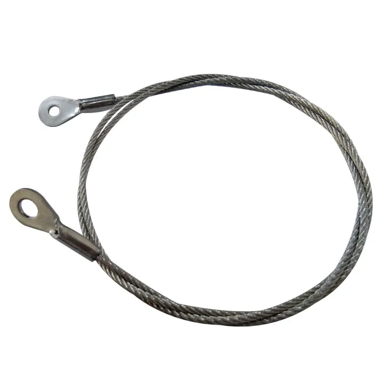
As a rigger or end-user of wire rope, it’s important to understand the types of terminations, or treatments, that can be used at the ends of a length of wire rope. These terminations are usually made by forming an eye or attaching a fitting, and are designed to be a permanent end termination on the wire rope where it connects to the load.
Wire rope is an extremely versatile mechanical device that can be used to help support and move an object or load. In the lifting and rigging industries, wire rope is attached to a crane or hoist and fitted with swivels, shackles or hooks to attach to a load and move it in a controlled matter. It can also be used to lift and lower elevators, or as a means of support for suspension bridges or towers.
In this article, we’ll explain what some of the following terms mean and how the can be used to terminate the end of a wire rope cable:Wire rope sockets—spelter sockets, swaged sockets, and wedge sockets
When you understand the construction and specifications of the wire rope you need, as well as the right type of end termination you need, you’ll be able to select the best performing and longest-lasting wire rope for the job at hand.
There are essentially two techniques that can be used to create a termination on a length of wire rope or cable:You can form an eye, or loop, in the wire rope
Eyes, or loops, can be created at one end of a length of wire rope by using a mechanical splice with a swaged sleeve, a hand-tucked splice, or wire rope clips.
A swaged socket is applied to the end of a wire rope cable and is then forced into place using special dies and a hydraulic machine called a swager. When properly applied with the correct sized fitting, swaged sockets have an efficiency rating of 100% of the breaking strength of the rope.
A poured socket, commonly referred to as a spelter socket, attaches a termination fitting onto the end of a wire rope cable by pouring molten zinc or resin into a socket that then hardens and holds the fitting onto the end of the cable.
Due to the rigidity of this type of termination, the wires of the rope are subject to fatigue where the wires enter the socket, if the poured socket is subject to constant vibration.
Wedge sockets secure the rope to the end attachment by passing it around a grooved, wedge-shaped piece of steel and pulling it down under load into the bowl of the fixture.
Wedge sockets are popular because they can be installed in field and adjusted in field – providing 80% efficiency of rope breaking strength. Wedge sockets are popular in applications where the wire rope may be subjected to abuse and abrasion—particularly in construction and mining applications.
Wire rope clips can be used to form a load bearing eye at the end of a cable or wire rope, or to connect two cables together with a lap splice. Wire rope clips are popular because they can be installed in the field and provide 80% efficiency of the rope breaking strength.
However, the use of wire rope clips is heavily regulated by ASME B30.26 Rigging Hardware. When using wire rope clips, the end user must account for the following:When using U-bolt wire rope clips, the saddle shall be placed on the live end of the wire rope, with the U-bolt on the dead-end side—NEVER SADDLE A DEAD HORSE!
After installation, the connection shall be loaded to at least the expected working load. After unloading, the wire rope clips shall be re-tightened to the torque specifications of the manufacturer or a Qualified Person.
This type of wire rope clip is essentially a U-bolt, two nuts, and a metal base (saddle) that can be made from forged steel or cast iron. Careful consideration and attention must be given to the way U-bolt type wire rope clips are installed.
The base of the wire rope clip is made from forged steel. Forged clips are heated and hammered into the desired shape—resulting in a consistent grain structure in the steel. Forged wire rope clips are used for critical, heavy-duty, overhead loads such as winch lines, crane hoist lines, support lines, guy lines, towing lines, tie downs, scaffolds, etc.
Malleable wire rope clips are used for making eye termination assemblies only with right regular lay wire rope and only for light duty uses with small applied loads, such as hand rails, fencing, guard rails, etc. The base of the wire rope clips is made from malleable cast iron, which may fracture under heavy use and does not have the desirable metal properties of steel, or the beneficial grain structure that a forged base has.
Double saddle wire rope clips consist of two saddles, each with a leg, and two nuts—one used on the top and one on the bottom. Double saddle wire rope clips can be used in either direction, so they take the guesswork out during installation when applying to the live end and the dead end of a piece of wire rope.
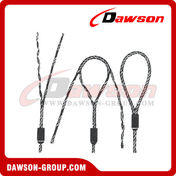
An eye splice may be used to terminate the loose end of a wire rope when forming a loop. The strands of the end of a wire rope are unwound and then the wire is bent around, and the unwrapped strands are then weaved back into the wire rope to form an eye.
A Flemish eye splice is created when the wire rope is opened, and the strands are laid out into two parts. The two strands are looped in opposite directions and then laid back together—forming an eye, or loop, at one end of the wire rope cable. The strands are then rolled back around the rope body and a metal sleeve fitting is slipped over the splice and swaged using hydraulic machinery. This splicing method provides the most efficient use of rope capacity and is highly economical.
A hand tucked splice is formed when the shorter “dead” end is tucked into the longer “live” end of the wire rope—forming an eye. These types of splices allow for easy inspection of the wire rope wires and strands.
When the end of a rope is turned back and formed into an eye, a thimble is often used to keep the shape of the eye, prevent the rope from being crushed, and keep the rope from being bent at a diameter smaller than the rope manufacturer’s recommendations.
The table below will explain the efficiencies of the different types of wire rope end terminations for both independent wire rope core (IWRC) and fiber core (FC) wire rope configurations. Rope efficiency is described as the ratio of a wire rope’s actual breaking strength and the aggregate strength of all individual wires tested separately—usually expressed as a percentage.IWRCFC
*Spelter sockets in smaller rope sizes (usually less than 7/16”) may not always develop 100% efficiency and are not recommended by some rope manufacturers.
When you need to order a replacement wire rope, understanding the right type of end termination will help to make sure you get a direct replacement rope so you can get your project back on track. We hope this article gives you a better understanding of terms related to sockets, wire rope clips, and eye splices and that you understand what type of end termination may be best for your application.
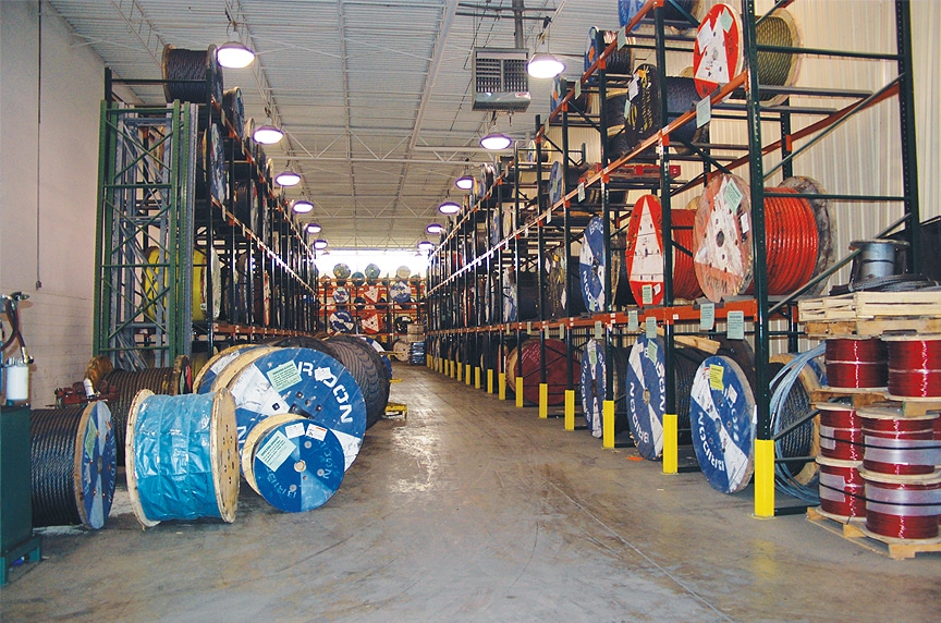
At Mazzella, we offer all different kinds of wire rope from all of the leading manufacturers. We sell the highest-quality domestic and non-domestic rigging products because product quality and operating safety go hand-in-hand. We have one of the largest and most complete inventories of both domestic and non-domestic rigging and lifting products to suit your lifting needs.
Wire rope splicing is essentially the formation of a knot between two parts of the same rope or between two separate ropes by separating and unravelling the strands and interweaving the threads together to produce a strong joint. Splicing forms a very strong knot which stays secure even if exposed to water.
There are different types of wire rope splicing. The two more common ones areBack or end splicing – This is a type of splicing where rope end strands are directly spliced without making a loop. With this wire rope splicing, rope ends are drawn to a close to prevent fraying.
Eye splicing – This a more popular type of wire rope splicing which involves taking the working end of the rope to form a loop at the end. The end of the rope strands are unraveled, then passed over and under against the lay of the rope to interweave it back into the main length of the rope.
Wire rope splicing maintains almost 95% of the wire rope’s strength. You can employ splicing in three-strand braided ropes, or even in over 12-strand braided ropes.
Splicing lets you create a new rope of any length, alter an existing rope to suit a changing application, or repair a damaged wire rope. There are two main disadvantages to splicing – the expanding thickness of the line at the joint and the distortion in the shape of the rope.
Check the wire rope tools and accessories section of this website for more tools or fill out the enquiry form and let us help with your wire rope splicing needs.
We custom manufacture wire rope assemblies (endless loop) for conveyor lines. Our specialty is the Long splice. The Long splice is used to create a continuous or endless loop of wire rope cable frequently utilized on conveyor systems. The splice is a difficult multi-step labor intensive process in which two wire rope cable ends are joined end to end and the strands are intertwined to merge the two individual wire rope cable ropes ends.
Our proven experience can be viewed first hand in the quality of our wire rope cable splices we perform regularly for diverse clientele in the Unites States and around the world. For assistance with your unique wire rope conveyor cable splicing needs, please complete theor call us directly at
Dec. 5, 1967 P. R. BAGBY IRE ROPE LONG SPLICE AND METHOD OF MAKING Filed May 7, 1965 Fxcer-4 l A VEN TOR. PERCY Q. SAC-15V ATTORNEYS United States Patent Ofiice 3,356,397 WIRE ROPE LONG SPLICE AND METHOD OF MAKING Percy R. Bagby, 27844 Conestoga Drive, Rolling Hills, Calif. 90274 Filed May 7, 1965, Ser. No. 453,950 2 Claims. (Cl. 287--78) The present invention relates to a wire rope pressed sleeve splice and to a method of making such a splice.
A common method of splicing wire rope is the long splice in which the two rope ends to be spliced are overlapped a predetermined length and the complemental strands of the rope ends are severed at longitudinallyspaced points. The conventional wire rope includes a core, and this core must be removed in the area adjacent the abutting ends of each pair of complemental strands in order to make the long splice. Each one of the severed ends is secured in position by tucking it into one of the open spaces formed by the removal of the fiber core. As many strand splices are formed as there are strands, and all of these splices constitute the long splice for the wire rope proper.
The prior art procedure for forming the long splice is a tedious and time-consuming operation, particularly that part of the operation in which the rope core is removed and replaced by the tucked ends of each complemental pair of strands in the rope. In addition, the procedure requires highly-skilled, experienced workmen, who may not readily be available when a wire rope unexpectedly parts. Nevertheless, this method of repairing wire rope has been used for many years because of certain advantages. That is, the strength of the wire rope is largely retained, losing only perhaps twenty percent because of the splice. This is apparently due to the appreciable length of the splice area which in a one-inch diameter rope may be 33 feet, with a 33-inch tuck for each of the strands. This length of splice provides a relatively large area of interengagement between the tucked strands and the adjacent strands so that the latter can exert a powerful clamping action and prevent the spliced ends from parting. In addition, the long splice is advantageous because the diameter of the wire rope in the splicearea is not appreciably increased. This in an important consideration in situations where the wire rope is, for example, formed into an endless loop for passage about sheaves and the like.
Accordingly, it is an object of the present invention to provide a method of long splicing the ends of a wire rope without the use of tucks while yet providing substantially the same tensile strength as the conventional, tucked long splice.
Another object of the invention is to provide a method of long splicing which can be quickly and easily accomplished by workmen having only a relatively rudimentary background in wire rope splicing techniques.
Another object of the invention is to provide a method of splicing the ends of a wire rope and which utilizes a plurality of pressed sleeves disposed about the rope. Each sleeve is applied to a strand splice and, by virtue of the number of such strand splices, the diameter and length of each sleeve can be reduced sufiiciently so as not to interfere with movement of the wire rope about sheaves or similar structure.
Another object of the invention is to provide a method of splicing or repairing a single damaged strand of a wire rope by pressing a sleeve about the damaged area.
Still another object of the invention is to provide a method of splicing a wire rope of that type having only circumferentially-arranged strands and no central core.
The present method is not limited to use with any particular length, diameter, number of strands, number 3,356,397 Patented Dec. 5, 1967 of wires per strand, wire arrangement, lay direction, lay type, type of core, or the like, and is applicable to the splicing or repair of wire ropes in general, as will be seen.
FIG. 1 is an elevational view of an exemplary short section of wire rope having six circumferentially arranged strands and a central fiber core, the rope section being shown parted in the middle;
FIG. 3 is a diagrammatic showing of the six strands of the wire rope of FIG. 1, illustrating the longitudinally spaced arrangement of the six splices over the splice length, the proximity of the splices being exaggerated so as to fit the drawing area;
FIG. 4 is an elevational view of a wire rope having six sleeves pressed about the rope to provide six splices longitudinally spaced along the splice length, the proximity of the splices being exaggerated to conform to the showing in FIG. 3;
FIG. 5 is an enlarged longitudinal cross-sectional view of one of the sleeves of FIG. 4, the sleeve being illustraed after it is pressed in position upon the wire rope; an
Referring now to the drawings, there is illustrated a conventional type of wire rope 10 having six outer strands 12, 14, 16, 18, 20 and 22 which are circumferentially arranged about a central fiber core 24. To facilitate the description which follows, the strands 12 through 20 of the rope end located to the left are designated a, while those in the rope end located to the right are designated b, as best viewed in FIGS. 1 and 3.
The wire rope 10 is merely exemplary and it will be understood that various other types of wire rope are equally suited for repair by use of the method and splice of the present invention.
According to the present method, the parted wire rope 10 is spliced by overlapping the rope ends a predetermined length sufficient to closely approach or equal the rated strength of the rope. In a one-inch rope this distance would be aproxirnately 33 feet. This overlap constitutes the splice area, and the individual strands are next severed, unlaid, and relaid in a particular manner toform the long splice. More particularly, ferrules or sleeves 26 are slid or threaded over the rope end to the left, out of the way of the splice area. Next, the strand 12a is unlaid from its rope end approximately the full length of the overlapped portion or splice length and severed. The corresponding strand 12b is then unlaid from its rope end and laid in the open groove formed in the first rope end by the removal of the strand 12a. The strands 12a and 1217 are then in end-abutting relation to define a splice joint. The fiber core 24 is preferably then severed the length of the strand 12a and the remaining core ends are abutted.
One of the sleeves 26 is next arranged about the adjacent pair of strands 12a and 12b and swaged or compressed over these strands. This also compresses the remaining strands of the rope end located on the left, as best seen in FIG. 3, and also compresses the core ends.
The tubular ferrules or sleeves 26 are made of any suitable high-strength material capable of cold flow under pressure into the wire and strand interstices of the rope ends. A sleeve of such material thus becomes an integral part of the rope and is capable of great holding power. Stainless steel is a preferred material because of its high strength and resistance to corrosion. High strength is desirable because it enables the use of relatively short, thin wall sleeves which facilitate movement of the rope about sheaves and the like. Preferably, the sleeve is kept below approximately twice the rope diameter, the sleeve lengthening somewhat during swaging. In this regard, it is noted that the swaging action compresses the wire rope, reducing its diameter somewhat, and also desirably reduces the thickness of the sleeve wall. In the example of the one-inch wire rope, the sleeve thickness is initially on the order of one-quarter inch when using stanless steel, that is, one-fourth the diameter of the wire rope. The finished diameter of the sleeve and rope would therefore be about one and one-eighth inches. Of course, the sleeve length and wall thickness will vary according to the wire rope diameter and type and the particular application for the wire rope.
After the strands 12a and 12b are sleeve-swaged together, the strand 14a is then severed at a point longitudinally spaced from the first splice but within the overlap or splice length. The strand 14b is then unlaid from its rope end and laid in the open groove formed by the removal of the strand 14a from the other rope end. The strand 14b is next severed to locate its severed end adjacent and in abutting relationship to the severed end of the strand 14a.
Next, the strand 16a is severed within the splice length and at a point longitudinally spaced from the last splice. The corresponding strand 16b is laid in the open groove formed by the removal of the strand 16a and is severed to locate its severed end in abutting relation to the severed end of the strand 16a. Another sleeve 26 is pressed about the abutting ends of the strands 16a and 16b, as will be apparent.
The operation is repeated with the strands 18a and 18b, the"strands 20a and 20b, and the strands 22a and 22b to provide the six splices illustrated in FIGS. 3 and 4. The six splices are illustrated in rather close proximity to enable their illustration in the space available. In actual practice the splices are located over a relatively long splice length, the length being approximately 33 feet for a one-inch wire rope, for example. Each splice is approximately six lays from the next splice.
The six splices constitute a long splice capable of carrying a load approaching or equaling the full rated strength of the wire rope, each of the sleeves developing approximately one-sixth of the load. Because the strength of the long splice is distributed over the six splice points, the cross section and length of each sleeve 26 can be reduced to a minimum. The use of the sleeves 26 thus provides a relatively quick and inexpensive means for long splicing wire rope. Tucks are completely eliminated. As a matter of fact, the present method can be used for splicing wire rope having no core, whereas the luck of a core greatly complicates present splicing practices since there is then no central core void within which to make tucks.
Various modifications and changes may be made with regard to the foregoing detailed description without departing from the spirit of the invention or the scope of the following claims.
1. A long splice for the severed strands of a wire rope and adapted for passage about a sheave or the like, said long splice comprising: complemental pairs of the severed strands of the rope ends arranged in abutting relation to define splice joints, the abutting ends of each of said pairs being axially spaced from the abutting ends of the others of said pairs whereby said splice joints are axially spaced along said wire rope;
and a plurality of sleeves pressed upon said rope and about all of said strands, said sleeves being axially spaced to locate a separate one of said sleeves about each of said splice joints, the length of each said sleeve being approximately twice the diameter of said Wire rope, the wall thickness of each said sleeve being not more than approximately one-fourth the diameter of said wire rope, and the axial spacing between adjacent ones of said splice joints being such that, upon passage of said long splice portion of said wire rope about a usual sheave, the section of said wire rope between adjacent said sleeves engages upon the periphery of the sheave.
References Cited UNITED STATES PATENTS 2,052,958 9/1936 Webb 287-78 2,461,079 2/1949 Peterson et a1. 57-142 2,482,204 10/ 1949 Peterson 57142 2,566,262 8/1951 Traxler 156-49 2,789,931 4/1957 Blue 15649 2,882,333 4/1959 Bertaux 28778 X 2,943,434 7/1960 Joy et al. 57-142 CARL W. TOMLIN, Primary Examiner.
Engineering wire rope slings for your application is a highly specialized field – with exacting standards – that we gladly live by. A Union sling can meet or exceed the most exacting specifications. We apply thorough design and production controls – including an extensive ISO-controlled process. And our traceability process tracks every component through completion of the assembly and into the field.
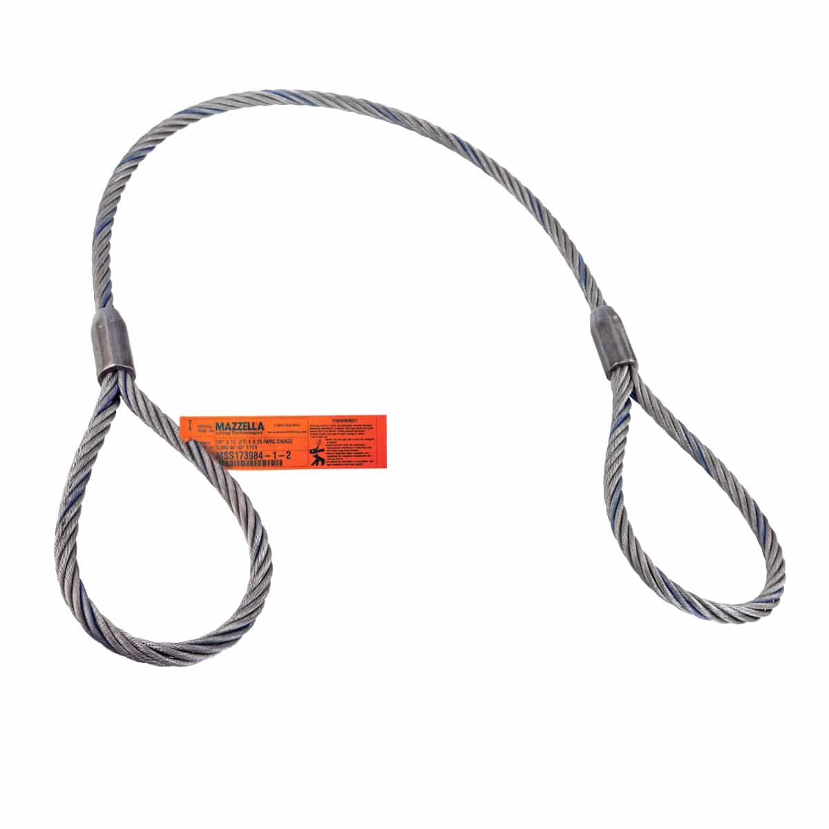
A mechanical-spliced wire rope sling is constructed when eyes are formed using the Flemish eye splice. Ends are then secured by pressing a metal sleeve over the ends of the strands of the splice. Pull is directly along the centerline of rope and eye. This splicing method gives the most efficient use of rope capacity and proves to be economical.
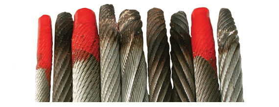
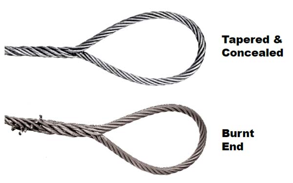
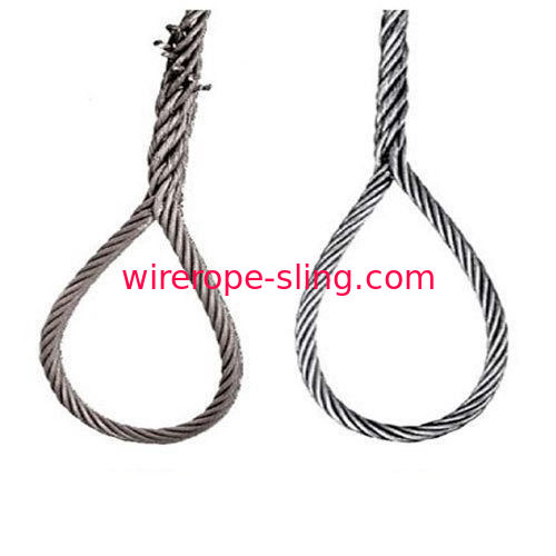
The end of a single wire rope is bent back along the rope to form the eye, and strands are hand-tucked into the body of the rope in what is called a burnt end splice. With Burnt End splices, the ends of strands are left exposed and cut off with a torch. Upon special request, a premium splice known as a tapered and concealed splice can be provided. Slings with rope bodies larger than 1" diameter are made only with Burnt End splices. All have the same rated capacity, size for size.
The tapered and concealed splice utilizes tension in the rope body to secure strands where they are tucked back into the rope. Needs no metal sleeve to assure firm anchoring. When "tapered" and "concealed", ends of strands are tucked inward and concealed inside the rope.

The Flemish eye is a type of circular loop at the end of a thread. There are several techniques of creating the eye with its knot tied back to the line, rope or wire.
There are various splicing techniques, and relate to whether a rope is braided or plaited, whether it has a core and whether the core is made of high-performance fibers. Techniques include:
For conventional stranded ropes, the ends of the rope are tucked (plaited) back into the standing end to form the loop. Three tucks are the minimum for natural fibers, five tucks are necessary for synthetics.
The ends of the rope are first wrapped in tape or heated with a flame to prevent each end from fraying completely. The rope is untwisted for a distance equal to three times the diameter for each "tuck", e.g., for five tucks in half inch rope, undo about 7.5 inches. Wrap the rope at that point to prevent it unwinding further. Form the loop and plait the three ends back against the twist of the rope. Practice is required to keep each end to retain its twist and lie neatly. In stiff old rope or in new rope which has been tightly wound, a marlinspike or fid can facilitate opening up the strands and threading each end.
In some cases, the splice is tapered by trimming the working strands after each tuck. Also, the splice can be whipped to protect and strengthen the splice. A rope thimble can be inserted in the eye to prevent chafing if the eye is to be permanently attached to a fixture (used when attaching a rope to a chain, for example).
An eight-strand rope consists of two left-twisting and two right-twisting pairs. Make sure the left-twisting strands are fed below left-twisting strands, and right-twisting strands below the right-twisting ones. Work systematically with different tape colours to keep from getting lost in the mess of strands. An eight-strand square plaited rope can be used as mooring line or anchor rode.
This technique is mostly used for Dyneema ropes.DSM advises using 60 times the diameter for coated Dyneema, and 100 times the diameter for uncoated Dyneema. For 6mm coated rope, this would mean 36 cm. Under tension the rope will pull into itself tightly, which produces a strong eye. One can pull out the eye when the rope is not under tension, unless one makes a lock-splice (also called brummel splice).
Splicing a rope with a laid core is usually more complicated than double braided polyester ropes. One needs more force to take the rope back into itself because there is often less room between the core and the cover.
A rope with parallel fibers in the core often has a tight inner cover to keep the fibers together. This splice is similar to the one for double braided polyester ropes; the main difference is that one cannot take the cover back in to the core because the fibers go through the core.
For ropes with a core of high-performance fibers (such as aramid fibers or Dyneema or Vectran) only the core determines the strength. The cover can be used optionally in the eye splice, for example, to add UV protection (for aramid fibers, such as Kevlar). Dyneema is very UV resistant and the cover is not needed. For these ropes, one could make an eye splice in the single braided core and leave the cover unused. There are ropes with an extra double layer cover; this is basically the same splice as for double braided except that the inner cover first needs to be removed over the length of the splice.
Depending on the type of splice and rope, there is a variety of tools available such as hollow fids, pulling needles and traditional splicing fids. Make sure to also have a marker, splicing tape, measuring tape and a knife or scissors at hand. Often a hammer and winch are used as well for tougher splices.
The bowline is a quick, practical method of forming a loop in the end of a piece of rope. However, the bowline has an awkward tendency to shake undone when not loaded. The bowline also reduces the strength of the rope at the knot to ~45% of the original unknotted strength.
A. Hyatt Verrill. "Chapter V - Shortenings, grommets, and selvagees". Knots, splices and rope work - A practival treatise. Fig. 90. Archived from the original on 2015-09-08. Retrieved 2015-08-10 – via Cosmopolitan University (online publisher).
We use Heavy Duty thimbles with all UNI-LOC® wire rope slings. They withstand the working load conditions of the slings but when severely overloaded they will noticeably stretch. Note that you can not feed this thimble through an identical one to make a choker hitch (use Slip-Through Thimbles).

Wire rope is often used in slings because of its strength, durability, abrasion resistance and ability to conform to the shape of the loads on which it is used. In addition, wire rope slings are able to lift hot materials.
Wire rope used in slings can be made of ropes with either Independent Wire Rope Core (IWRC) or a fiber-core. It should be noted that a sling manufactured with a fiber-core is usually more flexible but is less resistant to environmental damage. Conversely, a core that is made of a wire rope strand tends to have greater strength and is more resistant to heat damage.
Wire rope may be manufactured using different rope lays. The lay of a wire rope describes the direction the wires and strands are twisted during the construction of the rope. Most wire rope is right lay, regular lay. This type of rope has the widest range of applications. Wire rope slings may be made of other wire rope lays at the recommendation of the sling manufacturer or a qualified person.
Wire rope slings are made from various grades of wire rope, but the most common grades in use are Extra Improved Plow Steel (EIPS) and Extra Extra Improved Plow Steel (EEIPS). These wire ropes are manufactured and tested in accordance with ASTM guidelines. If other grades of wire rope are used, use them in accordance with the manufacturer"s recommendations and guidance.
When selecting a wire rope sling to give the best service, consider four characteristics: strength, ability to bend without distortion, ability to withstand abrasive wear, and ability to withstand abuse.
Rated loads (capacities) for single-leg vertical, choker, basket hitches, and two-, three-, and four-leg bridle slings for specific grades of wire rope slings are as shown in Tables 7 through 15.
Ensure that slings made of rope with 6×19 and 6x37 classifications and cable slings have a minimum clear length of rope 10 times the component rope diameter between splices, sleeves, or end fittings unless approved by a qualified person,
Ensure that braided slings have a minimum clear length of rope 40 times the component rope diameter between the loops or end fittings unless approved by a qualified person,
Ensure that grommets and endless slings have a minimum circumferential length of 96 times the body diameter of the grommet or endless sling unless approved by a qualified person, and
Perform welding of handles or other accessories to end attachments, except covers to thimbles, before assembly of the sling. Ensure that welded end attachments are proof tested by the manufacturer or a qualified person. Retain the certificates of proof test and make them available for examination.
Do not use wire rope clips to fabricate wire rope slings, except where the application precludes the use of prefabricated slings and where the sling is designed for the specific application by a qualified person,
Although OSHA"s sling standard does not require you to make and maintain records of inspections, the ASME standard contains provisions on inspection records.[3]
Ensure that wire rope slings have suitable characteristics for the type of load, hitch, and environment in which they will be used and that they are not used with loads in excess of the rated load capacities described in the appropriate tables. When D/d ratios (Fig. 4) are smaller than those listed in the tables, consult the sling manufacturer. Follow other safe operating practices, including:
Ensure that multiple-leg slings are selected according to Tables 7 through 15 when used at the specific angles given in the tables. Ensure that operations at other angles are limited to the rated load of the next lower angle given in the tables or calculated by a qualified person,
When D/d ratios (see Fig. 6) smaller than those cited in the tables are necessary, ensure that the rated load of the sling is decreased. Consult the sling manufacturer for specific data or refer to the WRTB (Wire Rope Technical Board) Wire Rope Sling Users Manual, and
Ensure that the load applied to the hook is centered in the base (bowl) of the hook to prevent point loading on the hook, unless the hook is designed for point loading,
Before initial use, ensure that all new swaged-socket, poured-socket, turnback-eye, mechanical joint grommets, and endless wire rope slings are proof tested by the sling manufacturer or a qualified person.
Permanently remove from service fiber-core wire rope slings of any grade if they are exposed to temperatures in excess of 180 degrees F (82 degrees C).
Follow the recommendations of the sling manufacturer when you use metallic-core wire rope slings of any grade at temperatures above 400 degrees F (204 degrees C) or below minus 40 degrees F (minus 40 degrees C).


 8613371530291