
wire rope clips osha free sample
This responds to your June 1, 1999, letter to the Occupational Safety and Health Administration (OSHA), requesting information on wire rope and Crosby clips used around the perimeter of buildings as a guardrail. You also requested clarification on when employees must tie-off when a guardrail system is removed to facilitate hoisting operations. We apologize for the long delay in providing this response.
Question 1: How many Crosby clips are required to be used when setting up a wire rope guardrail? Is it permissible to splice two wire ropes by overlapping or must the connections be turned back into eyelets and properly secured?
Answer: For construction work covered by 29 CFR 1926 Subpart M, §1926.502(b) sets forth the criteria that must be met when using wire rope as a guardrail. The standard requires guardrails to meet several specific criteria. For example, 1926.502(b)(3) states that the guardrail shall be capable of withstanding, without failure, a force of at least 200 pounds applied within 2 inches of the top edge, in any outward or downward direction, at any point along the top edge. Section 1926.502(b)(4) states that when the 200 pound test load noted in §1926.502(b)(3) is applied in a downward direction, the top edge of the guardrail shall not deflect to a height less than 39 inches above the walking/working level. Section 1926.502(b)(9) states that the top rail and mid-rails shall be at least ¼-inch nominal diameter or thickness to prevent cuts and lacerations. These and other criteria must be met when using wire rope as a guardrail around the perimeter of a building.
The OSHA standard does not specify a minimum number of clips when using wire rope as a guardrail. However, as a practical matter, it is unlikely you could meet the specific requirements under §1926.502(b) unless you follow the manufacturer"s recommendations for the number of clips to be used on wire ropes of different diameters (for example, the Crosby Group Inc. general catalog, 2000 edition has tables showing their recommendations for their clips). Also, note that OSHA"s standard for rigging equipment used for material handling, 29 CFR §1926.251, has a table for the number of clips required for wire rope ½-inch and greater. Although that standard does not apply to wire rope used for guardrails, when you design a rope system to meet the §1926.502 requirements, following those tables will normally ensure that you have enough clips.
If you need additional information, please contact us by fax at: U.S. Department of Labor, OSHA, Directorate of Construction, Office of Construction Standards and Guidance, fax # 202-693-1689. You can also contact us by mail at the above office, Room N3468, 200 Constitution Avenue, N.W., Washington, D.C. 20210, although there will be a delay in our receiving correspondence by mail.

Re: Wire rope clips on suspension scaffolds; safety latches on large crane hooks; hanging scaffolds - order of assembly; jobsite fabricated lifting accessories - criteria; and horizontal lifelines: use of wire rope clips, anchorages, number of persons allowed to be connected, requirements relating to sag, and use of synthetic rope.
This is in response to your facsimile dated November 14, 2003, to the Occupational Safety and Health Administration (OSHA). We have paraphrased your questions as follows:
Question 1(a) - (c): When using horizontal lifelines as part of personal fall arrest systems, what type of wire rope clips does OSHA require, and how many clips must be used? Additionally, what are the horizontal spacing criteria for the uprights?
Subpart M does not specify what type of wire rope clip or how many clips/clamps must be used when installing a horizontal lifeline. However, under §1926.502(d)(8), these decisions must be made under the supervision of a qualified person when the system is designed. The determination of the horizontal spacing criteria for uprights is also left to the qualified person"s supervisory approval.1
In an August 28, 2000 letter to Mr. Troxell2, we addressed the related issue of using wire rope clips on a wire rope guardrail. In that letter, we cautioned that, as a practical matter, it is unlikely that the criteria requirements for guardrails under §1926.502(b) could be met unless the manufacturer"s recommendations for the number of clips to be used on wire ropes of different diameters were followed (for example, the Crosby Group, Inc., general catalog 2000 edition, has tables showing their recommendations for their clips). We also pointed out that OSHA"s standard for rigging equipment used for material handling, 29 CFR 1926.251, has a table showing the number of clips required for wire rope ½-inch and greater. We noted that although that standard does not apply to wire rope used for guardrails, when designing a rope system to meet the §1926.502 guardrail requirements, following the tables at §1926.251 will normally ensure that there will be enough clips.
The forces exerted on a horizontal lifeline are substantially greater than those on a typical guardrail. Therefore, the system designer needs to ensure that the number, type, and location of clips will withstand the anticipated forces and meet the performance requirements in §1926.502 for horizontal lifelines.
Question 2: For a horizontal lifeline used as part of a personal fall arrest system during steel erection work, how tight should the lifeline be, and may synthetic rope be used for the horizontal lifeline?
Therefore, a qualified person is required to determine how tight the lifeline should be based on site-specific factors. No other requirements are imposed by OSHA regarding the tightness of the lifeline, so long as it comports with a safety factor of at least two.
With regard to the use of synthetic ropes, §1926.502(d)(14) specifies that, when using non-wire rope, synthetic rope (rather than nature fiber rope) must be used:
Question 4: Are there OSHA standards that specify criteria for constructing jobsite fabricated rigging equipment such as an equalizing beam, lifting beam, spreader beam, equalizing plates, tee lugs, lifting lugs, and welded scaffold brackets?
The only OSHA construction standards that contains specific criteria related to the construction of special custom design lifting accessories is 29 CFR 1926.251(a)(4), which states:
Question 5: Under §1926.451(d)(12)(v) and (vi), when wire rope clips are used on suspension scaffolds, "(v) U-bolt clips shall not be used at the point of suspension for any scaffold hoist," and "(vi) when U-bolt clips are used, the U-bolt shall be placed over the dead end of the rope, and the saddle shall be placed over the live end of the rope." Does §1926.451(d)(12)(v) contradict paragraph (d)(12)(vi)?
No. By its terms, §1926.451(d)(12)(v) prohibits the use of U-bolt clips at the point of suspension for any scaffold. The scaffold standard does not prohibit using U-bolt clips elsewhere. However, when using them elsewhere, under §1926.451(d)(12)(vi), the U-bolt must be placed over the dead end of the rope, and the saddle placed over the live end of the rope.
Question 6: Under §1926.251(c)(4)(iii), are eyes in wire rope bridles and slings or bull wires formed by wire rope clips permitted when used to lift scrap boxes or pendants?
This provision specifically prohibits eyes in wire rope bridles and slings or bull wires being formed by wire rope clips. There is no exception for lifting scrap boxes or pendants.
There are no OSHA standards setting criteria for horizontal high-lines. However, an employer"s use of a horizontal high-line must be in accordance with its obligations under Section 5(a)(1) of the Occupational Safety and Health Act (the "General Duty Clause"), which states:
In our view, the industry recognizes that the following engineering factors, among others, must be considered when designing horizontal high-lines: the span and sag of the wire rope line, the weight of the load being lifted, the initial tension of the rope line, and the size of the columns.
OSHA requirements for a safety latch on hooks do not depend of the size of the hook but rather the activity for which the hook is being used. Safety latches on hooks are required in two instances:
Knotting wire rope compromises the integrity of the strength of the wire rope and is therefore prohibited. Based on the picture provided, which showed a knot in wire rope secured by a U-bolt clip, this practice would be in violation of §1926.251(c)(3).
Question 10: Do OSHA standards require the attachment of an orange and white flag to the highest point of a crane that is being used in the vicinity of an airport?
There are no OSHA standards that require the highest point of a crane to be marked to enhance visibility to air traffic. However, the use of a crane in the vicinity of an airport may be subject to requirements set by other regulatory agencies, such as the Federal Aviation Administration.
Question 11: Do OSHA standards specify a particular anchorage point for connecting the lanyards of workers on crane suspended personnel platforms? Do the standards limit the number of such workers that can be attached to an anchorage point?
If you need additional information, please contact us by fax (202-693-1689) at: U.S. Department of Labor, OSHA, Office of Construction Standards and Guidance. You can also contact us by mail at U.S. Department of Labor, OSHA, Office of Construction Standards and Guidance, Room N3468, 200 Constitution Avenue, N.W., Washington, D.C. 20210, although there will be a delay in our receiving correspondence by mail.
This is in response to your January 26 letter requesting a waiver from an America National Standard Institute (ANSI) requirement addressing the use of wire rope clips in conjunction with wedge sockets. I apologize for the delay in responding to your inquiry.
The ANSI standard in question, ANSI A10.5c-1992, has not been formally adopted by OSHA, and therefore the ANSI provisions are not OSHA requirements to which the "waiver" (or "variance") procedures of the OSH Act would apply. OSHA does, however, frequently make reference to ANSI standards as evidentiary support for citations under the Act"s general duty clause. Your question, then, is really whether OSHA would cite an employer under the general duty clause for using a wire rope clip in a manner contrary to ANSI A10.5c-1992.
If an ANSI standard has not been adopted as an OSHA requirement, OSHA can independently evaluate whether noncompliance with an ANSI provision in a particular circumstance would also constitute a violation of the general duty clause. With regard to the use of a wire rope clip with a wedge socket, please be advised that in applications involving vibration, such as pile driving and clam shell operations, we would agree a wire rope clip may be used to clip the dead end of the rope to the live end to prevent the socket from working loose and the rope from jumping out of the groove of the wedge. The clip should be hand tightened with a wrench and not torqued to normal clip termination values. OSHA recommends, however, that a clip specifically designed for use with wedge sockets be used in this application.
For wedge socket applications not involving vibration, the policy is to use a wedge socket clip or to place a wire rope clip around the dead end of the line by clamping a short piece of rope, of the same diameter, to the tail.
These problems can be documented in our crane logs starting 23 May 1990. We are also using a 10 painted lead at the end of the controlled load lowering line as a guide for the operator to prevent two-blocking. While this is not as sophisticated as the anti-two block system, it is far more practical and successful on barge mounted equipment. When used in conjunction with all other OSHA requirements (i.e. prelift conference, test lift, etc.) we feel this to be a completely safe alternative, because of the very controlled nature of the lift.
Enclosed is a copy of a letter being forwarded for response. In the letter, an employer is requesting permission to use a wire rope clip to attach the "dead end rope tail" to the "live part" of a wire rope used with a wedge socket. This practice is prohibited by OSHA"s standards. The basis for the request is an article (copy enclosed) in the "Rigger"s Corner" section of the April/May 1993 issue of Lift Equipment. The article indicates it is advisable to clip the dead end of the rope to the live end since it prevents the wedge socket from working loose. The determination made relative to this issue will have national impact.
The Occupational Safety and Health Administration (OSHA) hereby revises the construction industry safety standards which regulate the design, construction, and use of scaffolds. The final rule updates the existing scaffold standards and sets performance-oriented criteria, where possible, to protect employees from scaffold-related hazards such as falls, falling objects, structural instability, electrocution and overloading.
In particular, the final rule has been updated to address types of scaffolds -- such as catenary scaffolds, step and trestle ladder scaffolds, and multi-level suspended scaffolds -- not covered by OSHA"s existing scaffold standards. In addition, the final rule allows employers greater flexibility in the use of fall protection systems to protect employees working on scaffolds and extends fall protection to erectors and dismantlers of scaffolds to the extent feasible.
The Occupational Safety and Health Act of 1970 (the OSH Act) authorized the Secretary of Labor to adopt established federal standards issued under other statutes, including the CSA, as occupational safety and health standards. Accordingly, the Secretary of Labor adopted the Construction Standards, which had been issued under the CSA, as OSHA standards. The Safety and Health Regulations for Construction were subsequently redesignated as 29 CFR part 1926. Standards addressing scaffolds, §§1926.451 and 1926.452, were adopted in subpart L of part 1926 as OSHA standards as part of this process.
Based on concerns regarding the effectiveness of the existing scaffold standards, OSHA began a complete review of subpart L in 1977. The Agency consulted the Advisory Committee on Construction Safety and Health (ACCSH) several times regarding draft revisions to subpart L.
Based on its review of existing subpart L, OSHA believes that certain provisions in the existing standards are outdated, redundant, or ambiguous. In addition, some types of scaffolds used in construction (e.g., catenary scaffolds) are not clearly addressed by the existing standards, and some provisions cover only certain types of scaffolds when they should apply to all. The final rule eliminates those unnecessary, outdated and redundant provisions (e.g., revised subpart L states the requirement for guardrails once, rather than 19 separate times as in the existing standard).
Scaffold-related incidents resulting in injuries and fatalities continue to occur despite the fact that OSHA has had a scaffold standard in place since 1971. However, the Agency believes that compliance with the new standard will be better than it has been in the past because this standard has been simplified, brought up to date, and strengthened to provide additional protection.
OSHA prepared the following statistical estimates (based on 4.5 million construction workers then covered by subpart L) to support the 1986 proposal for subpart L, based on a review of accident data prepared by the Bureau of Labor Statistics (BLS) (Ex. 3-1). The revised scaffold standards contain a number of provisions designed specifically to address the findings of this analysis.
Based on its analysis of the available data and its field experience in enforcing construction standards, the Agency has determined that employees using scaffolds are exposed to a significant risk of harm. Specifically, scaffold related fatalities still account for approximately 9% of all fatalities in the construction workplace. In addition, the above data indicate that the revised final standard would have prevented many of these accidents more effectively than compliance with the existing scaffold standards. Consequently, OSHA finds that the revision of its scaffold standards for construction is necessary to improve employee protection. OSHA has determined that, as revised, the standard clearly states employers" duties and the appropriate compliance measures.
Paragraph (b) of §1926.450 lists and defines all major terms used in subpart L. OSHA is revising its definitions for particular types of scaffolds by specifying whether a particular type of scaffold is a "supported" or a "suspension scaffold." OSHA believes that adding this information will make it easier for employers to identify the appropriate general requirements in final rule §1926.451.
The Agency has also revised subpart L definitions by deleting language that limits the use of a particular type of scaffold. Such substantive limitations are more appropriately placed in regulatory text. Accordingly, for example, OSHA has revised the definition for "bricklayers" square scaffolds" (a scaffold composed of framed wood squares which support a platform, limited to light and medium duty) by deleting the words "limited to light and medium duty". Similarly, OSHA has revised the definition for "coupler" to be "a device for locking together the component tubes of a tube and coupler scaffold", deleting language addressing the material used for the coupler because such requirements are more properly located in §§1926.451 or 1926.452.
OSHA agrees that the safety factors for the counterweights, riggings, direct connections to roofs and floors, and suspension ropes of adjustable suspension scaffolds should be related to the rated load of the hoist and the stall load of the hoist, and not be based on the maximum intended load.
Paragraph (a)(3) provides that "each suspension rope, including its connecting hardware, used on non-adjustable suspension scaffolds shall be capable of supporting, without failure, at least 6 times the maximum intended load applied or transmitted to that rope."
Paragraph (a)(4) of the final rule provides that "each suspension rope, including connecting hardware, used on adjustable suspension scaffolds shall be capable of supporting, without failure, at least 6 times the maximum intended load applied or transmitted to that rope with the scaffold operating at either (a) the rated load of the hoist, or (b) 2 (minimum) times the stall load of the hoist, whichever is greater".
Paragraph (a)(5) requires that the stall load of any scaffold hoist not exceed 3 times its rated load. OSHA finds that this requirement is reasonably necessary to prevent accidental overloading of suspension scaffold support systems. U.L. standard 1323 limits the output force of a scaffold hoist to three times the rated load of the hoist. As far as OSHA has been able to determine, the other laboratories which test and list scaffold hoists adhere to the requirements of U.L. 1323.
Paragraph (b)(1)(ii) provides that, where the exception created by paragraph (b)(1)(I) applies, employers shall place platform units as close together as possible, with the space between the platform and uprights not to exceed 9½ inches. OSHA set 9½ inches as the maximum space allowed, because the minimum width for scaffold units that could be expected to sustain a working load is just over 9½ inches.
Paragraph (b)(3)(I) requires that the front edges of outrigger scaffolds be no more than three inches from the face of the structure, as is required by §1926.451(g)(4) of OSHA"s existing standard.
Paragraph (b)(6), where platform units are abutted to create a long platform, each abutted end shall rest on a separate support surface. Abutted platform units do not rest one on another, but instead are end-to-end. Consequently, one unit does not support the other, and proper support can only be provided by separate support surfaces.
Paragraph (b)(10) requires that scaffold components manufactured by different manufacturers not be intermixed unless the component parts fit together without force and the resulting scaffold"s structural integrity is maintained by the user. Scaffold components manufactured by different manufacturers shall not be modified in order to intermix them unless the resulting scaffold is determined by a competent person to be structurally sound. OSHA expects that the competent person who evaluates the scaffold will have the appropriate knowledge, skill and experience regarding scaffold systems and components.
Paragraph (d)(3) sets requirements for the stabilization of outrigger beams. The paragraph requires that outrigger beams be secured directly to the supporting surface or be stabilized using counterweights, except that masons" multi-point adjustable suspension scaffolds shall not be stabilized by counterweights. The rule does not allow counterweights for stabilizing such masons" suspension scaffolds because, with the large loads often placed on masons" multi-point adjustable suspension scaffolds and the large counterweights that would be necessary to anchor such systems, OSHA is concerned that the supporting roof or floor would become dangerously overloaded.
Paragraph (d)(3)(I) provides that direct connections shall be evaluated by a competent person who affirms, based on that evaluation, that supporting surfaces can support the anticipated loads. In addition, the paragraph requires masons" multi-point adjustable suspension scaffold connections to be designed by an engineer experienced in such scaffold design. OSHA anticipates that compliance with these provisions will ensure that roof or floor decks are capable of supporting the loads to be imposed.
Paragraphs (d)(3)(vi) through (d)(3)(x) set requirements for securing outrigger beams. In particular, outrigger beams not stabilized by direct connections to the supporting surface shall be secured by tiebacks (paragraph (d)(3)(vi)). Tiebacks must be as strong as the suspension ropes (paragraph (d)(3)(vii)), be secured to a structurally sound anchorage (paragraph (d)(3)(ix)), and be installed perpendicular to the structure unless opposing angle tiebacks are installed (paragraph (d)(3)(x)). In addition, paragraph (d)(3)(viii) requires that outrigger beams be placed perpendicular to their bearing support, with the exception described more fully below.
OSHA has determined that it is reasonably necessary to require that counterweights be designed for no other purpose than to counterweight the system, and to prohibit the use of construction materials as counterweights. In addition, OSHA has determined that it is appropriate to require the marking of counterweights with their weights because that information is needed for the proper design, selection and installation of counterweights.
Paragraph (d)(4) specifies the construction requirements for outrigger beams used with suspension scaffolds. This provision requires that suspension scaffold outrigger beams be: provided with stop bolts or shackles at both ends; securely fastened together with the flanges turned out when channel iron beams are used in place of I-beams; installed with all bearing supports perpendicular to the beam center line; and set and maintained with the web in a vertical position. In addition, when an outrigger beam is used, the shackle or clevis with which the suspension rope is attached to the outrigger beam shall be placed directly over the hoisting machine, i.e., over the center line of the stirrup.
Paragraph (d)(5) sets requirements for suspension scaffold support devices other than outrigger beams. These devices include cornice hooks, roof irons, parapet clamps, or similar devices. Under this provision, those devices must be: made of steel, wrought iron, or materials of equivalent strength; supported by bearing blocks; secured against movement by tiebacks installed at right angles to the face of the building or structure unless opposing angle tiebacks are installed and secured to a structurally sound point of anchorage on the building or structure (sound points of anchorage include structural members, but do not include standpipes, vents, other piping systems, or electrical conduit); and tiebacks shall be equivalent in strength to the strength of the hoisting rope.
Paragraph (d)(6) specifies the minimum length of suspension rope to be used with different kinds of hoists. In particular, winding drum hoists are required to have at least four wraps of suspension rope at the lowest point of scaffold travel. All other types of hoists are required to have suspension rope long enough to lower scaffolds to the level below, without having the rope end pass through the hoist, or to have the rope end configured or provided with means so that the end does not pass through the hoist. Final rule paragraph (d)(7) states "The use of repaired wire rope as suspension rope is prohibited."
Paragraph (d)(8) provides that wire suspension ropes shall not be joined together except through the use of eye splice thimbles connected with shackles or cover plates and bolts.
Paragraph (d)(9) provides that the load end of wire suspension ropes shall be equipped with proper size thimbles and secured by eye splicing or equivalent means.
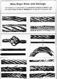
Paragraph (d)(10) requires that ropes be inspected for defects by a competent person prior to each work shift and after every occurrence which could affect a rope"s integrity. The wire rope shall be replaced if the rope has any physical damage which impairs its function and strength; any kinks that might impair the tracking or wrapping of rope around the drum(s) or sheave(s); six randomly distributed broken wires in one rope lay or three broken wires in one strand in one rope lay; abrasion, corrosion, scrubbing, flattening or peening causing loss of more than one-third of the original diameter of the outside wires; evidence of any heat damage resulting from a torch or any damage caused by contact with electrical wires; or evidence that a secondary brake has been activated during an overspeed condition and engages the suspension rope (paragraphs (d)(10)(I) through (vi)).
Paragraph (d)(11) requires that swaged attachments or spliced eyes on wire suspension ropes not be used unless they are made by the wire rope manufacturer or a qualified person. This provision is essential to ensure the strength and integrity of such attachments as eyes.
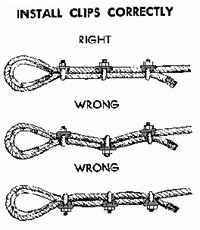
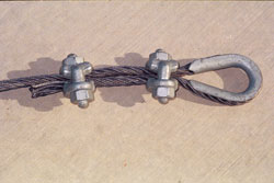
Paragraph (d)(12) requires that, when wire rope clips are used on suspension scaffolds, there shall be a minimum of 3 wire rope clips installed, with the clips a minimum of 6 rope diameters apart; employers shall follow the manufacturer"s recommendations when installing clips, retightening clips after initial loading, and inspecting and retightening clips at the start of each work shift; U-bolt clips (a variety of wire rope clip) shall not be used at the point of suspension for any scaffold hoist; and when U-bolt clips are used, the U-bolt shall be placed over the dead end of the rope, and the saddle shall be placed over the live end of the rope.
Paragraph (e)(2) sets requirements for portable, hook-on and attachable ladders. A note to this paragraph indicates that additional requirements for the proper construction and use of portable ladders are contained in subpart X of this part--Stairways and Ladders-- of the construction standards.
Paragraph (e)(4)(xi) requires that scaffold stairways be installed between 40 degrees and 60 degrees from the horizontal. OSHA has determined that scaffold stairways installed in the range of 40 degrees to 60 degrees from the horizontal will provide safe employee access and will still be capable of fitting into the confines of the scaffold frames.
Paragraph (e)(4)(xiii) requires riser heights within each flight of scaffold stairs to be uniform within 1/4 inch. OSHA believes that a uniform riser height within 1/4 inch (0.6 cm) for all steps in each flight of stairs is necessary in order to minimize the possibility that employees will slip, trip, and fall while they are on the stairs. OSHA recognizes that there are situations where the level of the ground or of the structure to which the stair tower is connected will cause the spacing of the top or bottom step of the stairway system to deviate from uniformity with the other steps by more than 1/4 inch. The Agency has determined that such deviation will not compromise employee safety, so long as the stair tower otherwise complies with the requirements of paragraph (e)(4). This is consistent with §1926.1052(a)(3).
Paragraph (e)(9) of the final rule sets access requirements for employees erecting or dismantling supported scaffolds. The introductory language of paragraph (e)(9) requires employers to comply with final paragraphs (e)(9)(I)-(iv) starting on September 2, 1997. OSHA has delayed implementation of this paragraph (as well as paragraph (g)(2)) so that affected employers have sufficient time to develop and implement the necessary measures. In addition, the delayed implementation allows time for OSHA to complete work on non-mandatory Appendix B, discussed below, which will provide examples of considerations that employers complying with paragraphs (e)(9) and (g)(2) would take into account.
Paragraph (e)(9)(I) provides that the means of access for erectors or dismantlers shall be determined by a competent person, based on specific site conditions and the type of scaffold being erected. As discussed in relation to the introductory text of final rule paragraph (e), while the Agency originally proposed to exempt erectors and dismantlers working on supported scaffolds from requirements for safe access, careful review of the record has led OSHA to the conclusion that a competent person is the appropriate individual to decide what the appropriate means of access for scaffold erectors and dismantlers is on any particular job, based on specific site conditions. Employers are required to have the erection, dismantling or alteration of a scaffold conducted under the supervision and direction of a competent person who is qualified in the pertinent subject matter.
Paragraph (f)(1) provides that scaffolds and scaffold components shall not be loaded in excess of their maximum intended loads or rated capacities, whichever is less. Compliance with this rule ensures that the scaffold"s capacity is not exceeded. OSHA believes it is appropriate to take into account the "expected" burden as well as the burden a scaffold "can" support without failure.
Paragraph (f)(2) prohibits the use of shore or lean-to scaffolds. Such scaffolds are not properly designed nor properly constructed, and pose a serious threat to anyone working on them.
Paragraph (f)(3) requires that scaffolds and scaffold components be inspected for visible defects by a competent person prior to each work shift and after any occurrence which could affect a scaffold"s structural integrity. OSHA has determined that inspections conducted by a competent person before each shift and after any occurrence that would affect the scaffold"s integrity will adequately protect employees working on scaffolds and ensure that defects are detected in a timely fashion.
Paragraph (f)(10) requires that support ropes used with adjustable suspension scaffolds have sufficient diameter for functioning of the brakes and the hoist mechanism.
Paragraph (f)(11) requires that suspension ropes be shielded when a heat-producing process is performed. When acids or other corrosive substances are used on a scaffold, the ropes shall be shielded, treated to protect against the corrosive substances, or shall be of a material which is not adversely affected by the substance being used.
Paragraphs (f)(15)(ii) through (iv) require that the platform units be secured to the scaffold to prevent them from moving; that the ladder legs are all on the same platform unit unless other means have been provided to stabilize the ladder against platform unit deflection; and that the ladder legs be secured to prevent them from slipping and being pushed off the platform unit. The Agency believes that compliance with these provisions will prevent the tipping and instability hazards that led OSHA to propose a prohibition against the use of ladders on all scaffolds.
Paragraph (f)(17) requires employers to reduce the possibility of welding current arcing through suspension wire rope while employees are performing welding from suspended scaffolds by insulating the suspended platform and its rigging. OSHA is adding this new provision to protect employees from the electrocution and platform collapse hazards posed by arcing welding current. In particular, the Agency requires that employers rig affected scaffolds with insulated thimbles (paragraph (f)(17)(I)), insulated wire rope (paragraph (f)(17)(ii)), and insulated hoist mechanisms (paragraph (f)(17)(iii)). This paragraph also specifies precautions for grounding the scaffold to the structure on which welding is being performed (paragraphs (f)(17)(iv - vi)). These provisions are consistent with ANSI A10.8-1988, Section 6.2.9.
OSHA has determined that compliance with the provisions of paragraph (f)(17), taken together, will minimize the hazards of electric arcing during welding operations on suspended scaffolds. The Agency has concluded that it is appropriate to address the hazard of arcing welding current during welding operations on suspended scaffolds in the final rule for scaffolds, rather than in the welding standards, because the precautions in question relate to the scaffold rigging, not to welding procedures, and because placing the pertinent regulatory text in the rule will facilitate compliance.
Paragraph (g) sets fall protection requirements for employees working on scaffolds, including criteria for guardrail systems. Fall hazards account for a high percentage of the injuries and fatalities experienced by scaffold workers. OSHA has determined that compliance with this paragraph will effectively protect employees from those hazards.
OSHA has carefully analyzed all of the comments and data available in the record and has determined that it is appropriate to maintain the 10-foot fall protection threshold. This is also the height requirement recommended by the current national consensus standard, ANSI A10.8-1988. This level differs from the 6-foot threshold for fall protection set in subpart M (Fall Protection) for other walking/working surfaces in construction because scaffolds, unlike these other surfaces, are temporary structures erected to provide a work platform for employees who are constructing or demolishing otherstructures. The same features that make scaffolds appropriate for short-term use in construction, such as ease of erection and dismantling) also make them less amenable to the use of fall protection at the time the first level is being erected. For example, the site preparation (such as leveling of the ground) that is done before a scaffold is erected is less thorough than the leveling performed prior to constructing a building. In addition, there is often no structure adjacent to a scaffold that can be used to anchor a personal fall arrest system, because the adjacent structure is in the process of being built or demolished.
Paragraph (g)(1)(ii) requires personal fall arrest systems and guardrail systems for all single-point adjustable suspension scaffolds (except boatswains" chairs), and for all two-point adjustable suspension scaffolds. The requirement to have guardrails and personal fall arrest systems on two-point scaffolds is based on the fact that a guardrail system alone does not provide adequate fall protection when a suspension rope fails and causes the scaffold to tip or hang from only one end. Personal fall arrest system protection is also necessary for single-point systems, because the fall hazard related to suspension rope failure is as serious as it is with the two-point scaffold. However, because personal fall arrest systems would be the primary means of fall protection on single-point and two-point systems, the provision allows a lower minimum strength guardrail system to be used.
Paragraph (g)(1)(iv) provides that employees on self-contained scaffolds be protected by both personal fall arrest systems and guardrail systems when the platform is supported by ropes (as when the scaffold is being raised or lowered on some systems) and by guardrail systems when the platform is supported directly by the scaffold frame.
Paragraph (g)(2) of the final rule addresses fall protection for employees erecting or dismantling supported scaffolds. OSHA has determined that it is appropriate to delay the implementation of paragraph (g)(2) until September 2, 1997. The delay will allow affected employers sufficient time to implement the appropriate procedures for addressing the fall protection needs of employees erecting or dismantling scaffolds. In addition, deferring compliance will allow time for the Agency to complete non-mandatory Appendix B, which will provide examples of considerations that a competent person would take into account when evaluating fall protection options for scaffold erectors and dismantlers. As discussed above in relation to final rule paragraph (e)(9), the Agency has also deferred requirements for safe access for scaffold erectors and dismantlers until September 2, 1997.
The Agency agrees that, if fall protection can be provided, it is the employer"s responsibility to take the actions necessary to protect employees. However, OSHA has determined, based on the information in the record, that in some situations, it is not possible to provide fall protection for erectors and dismantlers of supported scaffolds.
Employers must have valid reasons for not providing fall protection to scaffold erectors and dismantlers, but OSHA does not agree that the employer must put these reasons in writing. Compliance officers can substantiate employer claims of in feasibility or greater hazard through on-site observations and discussion with the competent person and other workers.
Paragraph (g)(3)(ii) states that horizontal lifelines, when used, shall be secured to two or more structural members of the scaffold, and shall not be attached only to the suspension ropes.
Paragraph (g)(3)(iii) provides that, when lanyards are connected to horizontal lifelines or structural members on a single-point or two-point adjustable suspension scaffold, the scaffold must be equipped with additional independent support lines and automatic locking devices capable of stopping the fall of the scaffold in the event one or more of the suspension ropes fail. The independent support lines must be equal in number and strength to the suspension ropes. OSHA believes that in the event of a suspension rope failure, the additional support lines will keep the scaffold from falling.
Paragraph (g)(3)(iv) provides that vertical lifelines, independent support lines, and suspension ropes must not be attached to each other, or be attached to or use the same point of anchorage, or be attached to the same point on the scaffold or body belt/harness system.
Paragraphs (g)(4)(iv) through (vi) specify the criteria necessary to ensure that the midrails, screens, mesh, and baluster type protection required by paragraph (g)(4)(iii) will be properly placed and effective.
Paragraph (g)(4)(xiv) requires that guardrail systems using manila, plastic or synthetic rope as rails be inspected by a competent person as frequently as necessary to ensure that the guardrails comply with the performance criteria in final rule §1926.451(g).
Paragraph (h)(3)(ii) requires the use of additional independent support lines to support the scaffold in the event of suspension support rope failure, in cases where canopies are used for falling object protection on suspended scaffolds.
Paragraph (h)(3)(iii) requires that independent support lines and suspension ropes not be attached to the same point of anchorage. This new provision will prevent the loss of the backup safety systems in the event of suspension rope anchorage failure.
OSHA has determined that compliance with the performance-oriented provisions of final rule §§1926.451 and 1926.452, taken together, will provide adequate protection for employees working on scaffolds. Further, the Agency believes that the specification language suggested by the commenters would limit innovation and impose unreasonable burdens on employers.
Paragraph (a) sets requirements for the proper use of bearers, braces and runners on pole scaffolds. The final rule has deleted the word "wood" from the title of the paragraph, since pole scaffolds can be constructed of other materials. In addition, the final rule provides that pole scaffolds over 60 feet in height be designed by a registered professional engineer, and must be constructed and loaded in accordance with that design. The provision also notes that non-mandatory Appendix A contains examples of criteria that will enable an employer to comply with design and loading requirements for pole scaffolds under 60 feet in height.
Paragraph (b)(4) requires that bracing be attached to the runners as close to the post as possible, where conditions preclude attachment of bracing to posts. Agency recognizes that attachment to the post, while the most desirable option, is not always possible. In circumstances where such attachment is not possible, OSHA has determined that attachment to the runner, as close as possible to the post, will still maximize directional stability and provide the strength necessary to properly brace the scaffold.
Paragraph (c)(5) specifies the proper placement of platform support brackets. Improper placement of such cantilever supports can significantly reduce their support capacity and thus endanger employees working on top of the platform.
Paragraph (h) This paragraph requires that scaffold brackets be constructed to fit the pitch of the roof and provide a level support for the platform (paragraph (h)(1)); and that brackets be anchored in place by nails unless it is impractical to use nails (paragraph (h)(2)). Paragraph (h)(2) further provides that brackets shall be held in place with first-grade manila rope of at least three-fourth inch diameter, or a rope with equivalent strength, when nails are not used. Reference 451(g)(1)(viii) for fall protection.
Paragraph §1926.452(I) Paragraphs (I)(1) through (I)(4), set requirements for the proper positioning and securing of outrigger beams. Paragraphs (I)(5) and (I)(6) require that the inboard ends of outrigger beams be securely anchored and that the entire supporting structure be securely braced.
Paragraph (I)(8) requires that scaffolds and scaffold components be designed by a registered professional engineer and constructed and loaded in accordance with such design. This provision reflects OSHA"s determination that the design of this type of scaffold involves calculations that required the skills of a registered professional engineer, and that the criteria in the proposed rule had such limited applicability as to be of virtually no help to employers in almost all situations.
Paragraph (k)(5) provides that scaffold platforms shall not be bridged one to another. The provision would prohibit situations where, for example, four ladders are used to support three platforms. OSHA is prohibiting bridging because this practice often leads to overloading of the two ladders in the middle. This provision does not prohibit passage from one scaffold to another if the scaffolds are close enough for employees to walk (but not to jump or swing) from one scaffold to the other.
Paragraph (n)(3) provides that ladders used to support step, platform, and trestle ladder scaffolds shall be placed, fastened, or equipped with devices to prevent slipping. Paragraph (n)(4) requires that scaffolds not be bridged one to another. Bridging, as discussed above under paragraph (k)(5), occurs when four ladders are used to support three platforms. OSHA is prohibiting bridging because this practice often leads to overloading of the two ladders in the middle. Although step, platform and trestle ladder scaffolds were not specifically addressed in OSHA"s existing scaffold rule, they are covered by the general requirements in existing rule §1926.451(a).
Paragraph (o)(2) addresses the circumstances under which the supporting rope between a scaffold and a suspension device is permitted to deviate from a vertical position (i.e., at a 90 degree angle from level grade). This paragraph requires that the supporting rope between the scaffold and the suspension device be kept vertical unless the following four conditions are met: the rigging must have been designed by a qualified person; the scaffold must be accessible to rescuers; the supporting rope must be protected to ensure that it will not chafe at any point where a change in direction occurs; and the scaffold must not be able to sway into another surface. Whenever swaying of the scaffold could bring the scaffold into contact with another surface, the supporting rope must be vertical, with no exceptions.
Paragraph (o)(3) requires that the tackle used with boatswains" chairs be ball bearing or bushed blocks containing safety hooks and properly "eye" spliced minimum five-eight (5/8) inch (1.6 cm) diameter first grade manila rope, or other rope that meets the performance criteria of the above-specified manila rope. OSHA recognizes that the use of an open hook could allow a chair to be dislodged if the rigging hung up on an obstruction. The corresponding ANSI standard, A10.8-1988, paragraph 6.14.5, provides for the use of a hook with a safety latch over the opening (safety hook) to prevent dislodging of the chair. The Agency agrees that it is appropriate to explicitly require that employers who have their employees use boatswains" chair rig their scaffolds with safety hooks. In addition, OSHA believes that locking safety hooks, such as are required for use with crane and derrick suspended personnel platforms (§1926.550(g)(4)(iv)(B)), would provide the most effective protection for affected employees.
Paragraph (o)(5) requires, except as provided in paragraph (o)(6), that boatswains" chair seat slings be a minimum of five-eight (5/8) inch (1.6 cm) diameter fiber or synthetic rope or other rope which satisfies equivalent performance criteria.
Paragraph (o)(6) requires that boatswains" chair seat slings be a minimum of three-eight (3/8) inch (1.0 cm) wire rope, when a heat-producing process such as gas or arc welding is being conducted. This provision is necessary to ensure that the chair"s sling is made of fire-resistant materials.
Paragraph (p)(3) provides that the blocks for fiber or synthetic ropes consist of at least one double and one single block, and that the sheaves of all blocks fit the size of the rope used.
Paragraph (p)(5) requires that two-point scaffolds not be bridged or otherwise connected one to another during raising and lowering operations unless the bridge connections are articulated and the hoists properly sized. It is not intended to prohibit passage from one scaffold to another, but to prevent significant overloading of the hoist nearest the bridging device during operation of the hoist, or displacement of the bridge if the hoist is used to raise or lower one of the scaffolds. Many hoists are only sized to support one end of a two-point system. If one of two bridged scaffolds were to be raised by a hoist, a bridge laid between the scaffolds could be displaced unless the bridge is articulated (connected). This could also significantly increase the load on the hoist if it is not properly sized. The final rule addresses these two hazards by requiring bridge connections to be articulated and requiring that hoists be properly sized.
Paragraph (q)(1) provides that, when two or more scaffolds are used, they shall not be bridged one to another unless they are designed to be bridged, the bridge connections are articulated (connected), and the hoists are properly sized.
Paragraph (r)(2) requires that platforms supported by wire ropes have hook-shaped stops on each end of the platforms to prevent the platforms from slipping off the wire ropes. These hooks shall be so placed that they will prevent the platforms from falling if one of the horizontal wire ropes breaks. This language is consistent with the corresponding provision of ANSI A10.8-1988, paragraph 20.1.
Paragraph (r)(3) of the final rule provides that wire ropes shall not be tightened to the extent that the application of a scaffold load will over stress them. This provision is consistent with the corresponding language of ANSI A10.8-1988, paragraph 20.2.
Paragraph (r)(4) requires that wire ropes be continuous and without splices between anchors. This language is consistent with the corresponding language in ANSI A10.8-1988, paragraph 20.2, and is necessary to ensure that the rope has sufficient integrity to handle the load.
Paragraph (s)(2) provides that rope connections shall be such that the platform cannot shift or slip. Platform slippage is a significant factor in scaffold accidents.
Paragraph (s)(3) provides that, when only two ropes are used with each float, those ropes shall be arranged so as to provide four ends which are securely fastened to overhead supports, and each supporting rope shall be hitched around one end of the bearer and pass under the platform to the other end of the bearer where it is hitched again, leaving sufficient rope at each end for the supporting ties.
Paragraph (t)(3) provides that suspension ropes and cables be connected to the overhead supporting members by shackles, clips, thimbles, or by other means which provide equivalent strength, security and durability.
Paragraph (u)(2) provides that ropes or hangers be used for supports, except that one end of a needle beam scaffold may be supported by a permanent structural member. This provision is based on existing §§1926.451(p)(2) and (8), and is necessary to ensure that these scaffolds are properly supported by rope or hangers that meet the strength criteria of §1926.451(a).
Paragraph (u)(3) requires that the ropes be securely attached to the needle beams. This is a change from existing §1926.451(p)(3), which specified that all rope attachments must be either a scaffold hitch or properly made eye splices. OSHA determined that the existing rule is too restrictive, because other knots and means of attachment, such as wire rope clips, can adequately support the scaffold without decreasing employee safety.
Paragraph (v)(1) requires that multi-level suspended platform scaffolds be equipped with additional independent support lines, equal in number to the number of points supported and of equivalent strength to the suspension ropes, and be rigged to support the scaffold in the event the suspension rope(s) fail. These additional lines would support the scaffold, and prevent collapse in the event of primary support line failure.
Paragraph (v)(2) provides that the independent support lines and suspension ropes shall not be attached to the same points of anchorage. This provision reflects OSHA concern that the independent support lines would not protect workers from scaffold collapse if the independent lines and the suspension ropes were attached to the same anchorage point when the anchorage failed.
Paragraph (w) provides additional rules for mobile scaffolds. This paragraph applies to all mobile scaffolds, not just to those which are manually propelled.
Paragraph (w)(4) requires that power systems used to propel mobile scaffolds be designed for such use. In addition, forklifts, trucks, similar motor vehicles, or add-on motors shall not be used to propel scaffolds unless the scaffold is designed for such propulsion systems.
When power systems are used, the propelling force shall be applied directly to the wheels, and shall not produce a speed in excess of one foot per second (0.3 mps) (w)(6)(iv)); and
The Agency described such scaffolds as consisting of platforms supported by brackets which are secured in place by one or more wire ropes placed in an approximately horizontal plane around the circumference of the structure and tensioned by a turnbuckle.
Paragraph (x)(2) requires that each bracket be attached to the securing wire rope (or ropes) by a positive locking device capable of preventing the unintentional detachment of the bracket from the rope, or by some other means which prevents unintentional detachment.
Paragraph (x)(5) provides that, when a wire rope is placed around a structure to provide safe anchorage for personal fall arrest systems that are used by employees erecting or dismantling repair bracket scaffolds, the wire rope shall be at least 5/16 inches in diameter and shall, in all other respects, satisfy the requirements of subpart M, OSHA"s Fall Protection Standard.
Paragraph (x)(6) requires that each wire rope used for securing brackets in place or as an anchorage for personal fall arrest systems be protected from damage due to contact with edges, corners, protrusions, or other discontinuities of the supporting structure or scaffold components.
Paragraph (x)(7) provides that tensioning of each wire rope used for securing brackets in place or as an anchorage for personal fall arrest systems shall be by means of a turnbuckle at least 1 inch in diameter, or by some other equivalent means. OSHA has allowed employers the flexibility to use means other than a single turnbuckle for tensioning wire ropes, where the alternative means provide equivalent tension, because the Agency wants to encourage innovation and provide flexibility. In addition, OSHA anticipates that there may be circumstances where more than one turnbuckle will be needed to tension the wire rope, depending on the diameter of the chimney.
Paragraph (x)(9) provides that U-bolt wire rope clips shall not be used on any wire rope used to secure brackets or to serve as an anchor for personal fall arrest systems. OSHA is concerned that the use of U-bolt wire rope clips as wire rope fasteners on the horizontal support ropes could result in damage to the dead end of the rope. Further, if a segment of damaged dead end later were to become part of the live end due to an increase in the circumference of the structure, the Agency was concerned that the wire rope would be unable to support the loads imposed on it.
Paragraph (y)(4) of the final rule provides that stilts shall be properly maintained and that any alterations of the original equipment must be approved by the manufacturer.

(4) For rope-grab-type deceleration systems, the length of the lifeline above the centerline of the grabbing mechanism to the lifeline"s anchorage point should not exceed 2 feet (0.61 m).
(5) For lanyard systems, for systems with deceleration devices which do not automatically limit free fall distance to 2 feet (0.61 m ) or less, and for systems with deceleration devices which have a connection distance in excess of 1 foot (0.3 m) (measured between the centerline of the lifeline and the attachment point to the body belt or harness), the test weight should be rigged to free fall a distance of 7.5 feet (2.3 m) from a point that is 1.5 feet (.46 m) above the anchorage point, to its hanging location (6 feet below the anchorage). The test weight should fall without interference, obstruction, or hitting the floor or ground during the test. In some cases a non-elastic wire lanyard of sufficient length may need to be added to the system (for test purposes) to create the necessary free fall distance.
(2) "Rope-grab-type deceleration devices." (i) Devices should be moved on a lifeline 1,000 times over the same length of line a distance of not less than 1 foot (30.5 cm), and the mechanism should lock each time.
(a) "Selection and use considerations." (1) The kind of personal fall arrest system selected should match the particular work situation, and any possible free fall distance should be kept to a minimum. Consideration should be given to the particular work environment. For example, the presence of acids, dirt, moisture, oil, grease, etc., and their effect on the system, should be evaluated. Hot or cold environments may also have an adverse effect on the system. Wire rope should not be used where an electrical hazard is anticipated. As required by the standard, the employer must plan to have means available to promptly rescue an employee should a fall occur, since the suspended employee may not be able to reach a work level independently.
(d) "Employee training considerations." Thorough employee training in the selection and use of personal fall arrest systems is imperative. Employees must be trained in the safe use of the system. This should include the following: application limits; proper anchoring and tie-off techniques; estimation of free fall distance, including determination of deceleration distance, and total fall distance to prevent striking a lower level; methods of use; and inspection and storage of the system. Careless or improper use of the equipment can result in serious injury or death. Employers and employees should become familiar with the material in this Appendix, as well as manufacturer"s recommendations, before a system is used. Of uppermost importance is the reduction in strength caused by certain tie-offs (such as using knots, tying around sharp edges, etc.) and maximum permitted free fall distance. Also, to be stressed are the importance of inspections prior to use, the limitations of the equipment, and unique conditions at the worksite which may be important in determining the type of system to use.
(e) "Instruction considerations." Employers should obtain comprehensive instructions from the supplier as to the system"s proper use and application, including, where applicable:
(6) Proper hook-up, anchoring and tie-off techniques, including the proper dee-ring or other attachment point to use on the body belt and harness for fall arrest;
(g) "Inspection considerations." As required by 1926.502(d)(21), personal fall arrest systems must be regularly inspected. Any component with any significant defect, such as cuts, tears, abrasions, mold, or undue stretching; alterations or additions which might affect its efficiency; damage due to deterioration; contact with fire, acids, or other corrosives; distorted hooks or faulty hook springs; tongues unfitted to the shoulder of buckles; loose or damaged mountings; non-functioning parts; or wearing or internal deterioration in the ropes must be withdrawn from service immediately, and should be tagged or marked as unusable, or destroyed.
(h) "Tie-off considerations." (1) One of the most important aspects of personal fall protection systems is fully planning the system before it is put into use. Probably the most overlooked component is planning for suitable anchorage points. Such planning should ideally be done before the structure or building is constructed so that anchorage points can be incorporated during construction for use later for window cleaning or other building maintenance. If properly planned, these anchorage points may be used during construction, as well as afterwards.
(i) Properly planned anchorages should be used if they are available. In some cases, anchorages must be installed immediately prior to use. In such cases, a registered professional engineer with experience in designing fall protection systems, or another qualified person with appropriate education and experience should design an anchor point to be installed.
(ii) In other cases, the Agency recognizes that there will be a need to devise an anchor point from existing structures. Examples of what might be appropriate anchor points are steel members or I-beams if an acceptable strap is available for the connection (do not use a lanyard with a snaphook clipped onto itself); large eye-bolts made of an appropriate grade steel; guardrails or railings if they have been designed for use as an anchor point; or masonry or wood members only if the attachment point is substantial and precautions have been taken to assure that bolts or other connectors will not pull through. A qualified person should be used to evaluate the suitable of these "make shift" anchorages with a focus on proper strength.
(2) Employers and employees should at all times be aware that the strength of a personal fall arrest system is based on its being attached to an anchoring system which does not reduce the strength of the system (such as a properly dimensioned eye-bolt/snap-hook anchorage). Therefore, if a means of attachment is used that will reduce the strength of the system, that component should be replaced by a stronger one, but one that will also maintain the appropriate maximum arrest force characteristics.
(3) Tie-off using a knot in a rope lanyard or lifeline (at any location) can reduce the lifeline or lanyard strength by 50 percent or more. Therefore, a stronger lanyard or lifeline should be used to compensate for the weakening effect of the knot, or the lanyard length should be reduced (or the tie-off location raised) to minimize free fall distance, or the lanyard or lifeline should be replaced by one which has an appropriately incorporated connector to eliminate the need for a knot.
(4) Tie-off of a rope lanyard or lifeline around an "H" or "I" beam or similar support can reduce its strength as much as 70 percent due to the cutting action of the beam edges. Therefore, use should be made of a webbing lanyard or wire core lifeline around the beam; or the lanyard or lifeline should be protected from the edge; or free fall distance should be greatly minimized.
(5) Tie-off where the line passes over or around rough or sharp surfaces reduces strength drastically. Such a tie-off should be avoided or an alternative tie-off rigging should be used. Such alternatives may include use of a snap-hook/dee ring connection, wire rope tie-off, an effective padding of the surfaces, or an abrasion-resistance strap around or over the problem surface.
(7) The strength of an eye-bolt is rated along the axis of the bolt and its strength is greatly reduced if the force is applied at an angle to this axis (in the direction of shear). Also, care should be exercised in selecting the proper diameter of the eye to avoid accidental disengagement of snap-hooks not designed to be compatible for the connection.
(j) "Snap-hook considerations." (1) Although not required by this standard for all connections until January 1, 1998, locking snaphooks designed for connection to suitable objects (of sufficient strength) are highly recommended in lieu of the nonlocking type. Locking snaphooks incorporate a positive locking mechanism in addition to the spring loaded keeper, which will not allow the keeper to open under moderate pressure without someone first releasing the mechanism. Such a feature, properly designed, effectively prevents roll-out from occurring.
(2) As required by 1926.502(d)(6), the following connections must be avoided (unless properly designed locking snaphooks are used) because they are conditions which can result in roll-out when a nonlocking snaphook is used:
(vi) Improper dimensions of the dee-ring, rebar, or other connection point in relation to the snaphook dimensions which would allow the snaphook keeper to be depressed by a turning motion of the snaphook.
(l) "Elongation and deceleration distance considerations." Other factors involved in a proper tie-off are elongation and deceleration distance. During the arresting of a fall, a lanyard will experience a length of stretching or elongation, whereas activation of a deceleration device wil


 8613371530291