
wire rope clips osha brands

Re: Wire rope clips on suspension scaffolds; safety latches on large crane hooks; hanging scaffolds - order of assembly; jobsite fabricated lifting accessories - criteria; and horizontal lifelines: use of wire rope clips, anchorages, number of persons allowed to be connected, requirements relating to sag, and use of synthetic rope.
This is in response to your facsimile dated November 14, 2003, to the Occupational Safety and Health Administration (OSHA). We have paraphrased your questions as follows:
Question 1(a) - (c): When using horizontal lifelines as part of personal fall arrest systems, what type of wire rope clips does OSHA require, and how many clips must be used? Additionally, what are the horizontal spacing criteria for the uprights?
Subpart M does not specify what type of wire rope clip or how many clips/clamps must be used when installing a horizontal lifeline. However, under §1926.502(d)(8), these decisions must be made under the supervision of a qualified person when the system is designed. The determination of the horizontal spacing criteria for uprights is also left to the qualified person"s supervisory approval.1
In an August 28, 2000 letter to Mr. Troxell2, we addressed the related issue of using wire rope clips on a wire rope guardrail. In that letter, we cautioned that, as a practical matter, it is unlikely that the criteria requirements for guardrails under §1926.502(b) could be met unless the manufacturer"s recommendations for the number of clips to be used on wire ropes of different diameters were followed (for example, the Crosby Group, Inc., general catalog 2000 edition, has tables showing their recommendations for their clips). We also pointed out that OSHA"s standard for rigging equipment used for material handling, 29 CFR 1926.251, has a table showing the number of clips required for wire rope ½-inch and greater. We noted that although that standard does not apply to wire rope used for guardrails, when designing a rope system to meet the §1926.502 guardrail requirements, following the tables at §1926.251 will normally ensure that there will be enough clips.
The forces exerted on a horizontal lifeline are substantially greater than those on a typical guardrail. Therefore, the system designer needs to ensure that the number, type, and location of clips will withstand the anticipated forces and meet the performance requirements in §1926.502 for horizontal lifelines.
Question 2: For a horizontal lifeline used as part of a personal fall arrest system during steel erection work, how tight should the lifeline be, and may synthetic rope be used for the horizontal lifeline?
Therefore, a qualified person is required to determine how tight the lifeline should be based on site-specific factors. No other requirements are imposed by OSHA regarding the tightness of the lifeline, so long as it comports with a safety factor of at least two.
With regard to the use of synthetic ropes, §1926.502(d)(14) specifies that, when using non-wire rope, synthetic rope (rather than nature fiber rope) must be used:
Question 4: Are there OSHA standards that specify criteria for constructing jobsite fabricated rigging equipment such as an equalizing beam, lifting beam, spreader beam, equalizing plates, tee lugs, lifting lugs, and welded scaffold brackets?
The only OSHA construction standards that contains specific criteria related to the construction of special custom design lifting accessories is 29 CFR 1926.251(a)(4), which states:
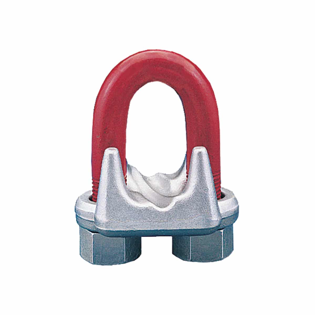
Question 5: Under §1926.451(d)(12)(v) and (vi), when wire rope clips are used on suspension scaffolds, "(v) U-bolt clips shall not be used at the point of suspension for any scaffold hoist," and "(vi) when U-bolt clips are used, the U-bolt shall be placed over the dead end of the rope, and the saddle shall be placed over the live end of the rope." Does §1926.451(d)(12)(v) contradict paragraph (d)(12)(vi)?
No. By its terms, §1926.451(d)(12)(v) prohibits the use of U-bolt clips at the point of suspension for any scaffold. The scaffold standard does not prohibit using U-bolt clips elsewhere. However, when using them elsewhere, under §1926.451(d)(12)(vi), the U-bolt must be placed over the dead end of the rope, and the saddle placed over the live end of the rope.
Question 6: Under §1926.251(c)(4)(iii), are eyes in wire rope bridles and slings or bull wires formed by wire rope clips permitted when used to lift scrap boxes or pendants?
This provision specifically prohibits eyes in wire rope bridles and slings or bull wires being formed by wire rope clips. There is no exception for lifting scrap boxes or pendants.
There are no OSHA standards setting criteria for horizontal high-lines. However, an employer"s use of a horizontal high-line must be in accordance with its obligations under Section 5(a)(1) of the Occupational Safety and Health Act (the "General Duty Clause"), which states:
In our view, the industry recognizes that the following engineering factors, among others, must be considered when designing horizontal high-lines: the span and sag of the wire rope line, the weight of the load being lifted, the initial tension of the rope line, and the size of the columns.
OSHA requirements for a safety latch on hooks do not depend of the size of the hook but rather the activity for which the hook is being used. Safety latches on hooks are required in two instances:
Knotting wire rope compromises the integrity of the strength of the wire rope and is therefore prohibited. Based on the picture provided, which showed a knot in wire rope secured by a U-bolt clip, this practice would be in violation of §1926.251(c)(3).
Question 10: Do OSHA standards require the attachment of an orange and white flag to the highest point of a crane that is being used in the vicinity of an airport?
There are no OSHA standards that require the highest point of a crane to be marked to enhance visibility to air traffic. However, the use of a crane in the vicinity of an airport may be subject to requirements set by other regulatory agencies, such as the Federal Aviation Administration.
Question 11: Do OSHA standards specify a particular anchorage point for connecting the lanyards of workers on crane suspended personnel platforms? Do the standards limit the number of such workers that can be attached to an anchorage point?
If you need additional information, please contact us by fax (202-693-1689) at: U.S. Department of Labor, OSHA, Office of Construction Standards and Guidance. You can also contact us by mail at U.S. Department of Labor, OSHA, Office of Construction Standards and Guidance, Room N3468, 200 Constitution Avenue, N.W., Washington, D.C. 20210, although there will be a delay in our receiving correspondence by mail.
This responds to your June 1, 1999, letter to the Occupational Safety and Health Administration (OSHA), requesting information on wire rope and Crosby clips used around the perimeter of buildings as a guardrail. You also requested clarification on when employees must tie-off when a guardrail system is removed to facilitate hoisting operations. We apologize for the long delay in providing this response.
Question 1: How many Crosby clips are required to be used when setting up a wire rope guardrail? Is it permissible to splice two wire ropes by overlapping or must the connections be turned back into eyelets and properly secured?
Answer: For construction work covered by 29 CFR 1926 Subpart M, §1926.502(b) sets forth the criteria that must be met when using wire rope as a guardrail. The standard requires guardrails to meet several specific criteria. For example, 1926.502(b)(3) states that the guardrail shall be capable of withstanding, without failure, a force of at least 200 pounds applied within 2 inches of the top edge, in any outward or downward direction, at any point along the top edge. Section 1926.502(b)(4) states that when the 200 pound test load noted in §1926.502(b)(3) is applied in a downward direction, the top edge of the guardrail shall not deflect to a height less than 39 inches above the walking/working level. Section 1926.502(b)(9) states that the top rail and mid-rails shall be at least ¼-inch nominal diameter or thickness to prevent cuts and lacerations. These and other criteria must be met when using wire rope as a guardrail around the perimeter of a building.
The OSHA standard does not specify a minimum number of clips when using wire rope as a guardrail. However, as a practical matter, it is unlikely you could meet the specific requirements under §1926.502(b) unless you follow the manufacturer"s recommendations for the number of clips to be used on wire ropes of different diameters (for example, the Crosby Group Inc. general catalog, 2000 edition has tables showing their recommendations for their clips). Also, note that OSHA"s standard for rigging equipment used for material handling, 29 CFR §1926.251, has a table for the number of clips required for wire rope ½-inch and greater. Although that standard does not apply to wire rope used for guardrails, when you design a rope system to meet the §1926.502 requirements, following those tables will normally ensure that you have enough clips.
If you need additional information, please contact us by fax at: U.S. Department of Labor, OSHA, Directorate of Construction, Office of Construction Standards and Guidance, fax # 202-693-1689. You can also contact us by mail at the above office, Room N3468, 200 Constitution Avenue, N.W., Washington, D.C. 20210, although there will be a delay in our receiving correspondence by mail.

We are a full service rigging supply company located in Ridgway, Pennsylvania. Our location is fully equipped to handle your wire rope fabricating, chain and synthetic sling and hardware needs.
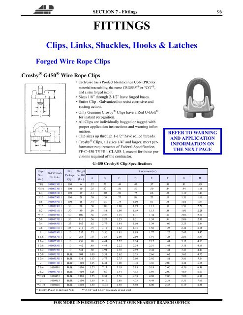
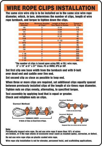
Efficiency ratings for wire rope end terminations are based upon the minimum breaking force of wire rope. The efficiency rating of a properly prepared loop or thimble-eye termination for clip sizes 1/8” through 7/8” is 80%, and for sizes 1” through 3-1/2” is 90%.
The number of clips shown (see Table 1) is based upon using RRL or RLL wire rope, 6 x 19 or 6 x 36 Class, FC or IWRC; IPS or XIP, XXIP. If Seale construction or similar large outer wire type construction in the 6 x 19 Class is to be used for sizes 1 inch and larger, add one additional clip. If a pulley (sheave) is used for turning back the wire rope, add one additional clip.
The number of clips shown also applies to rotation-resistant RRL wire rope, 8 x 19 Class, IPS, XIP, XXIP sizes 1-1/2 inch and smaller; and to rotation-resistant RRL wire rope, 19 x 7 Class, IPS, XIP, XXIP sizes 1-3/4 inch and smaller. For other classes of wire rope not mentioned above, we recommend contacting Crosby Engineering to ensure the desired efficiency rating.
For elevator, personnel hoist, and scaffold applications, refer to ANSI A17.1 and ANSI A10.4. These standards do not recommend U-Bolt style wire rope clip terminations. The style wire rope termination used for any application is the obligation of the user.For OSHA (Construction) applications, see OSHA 1926.251.
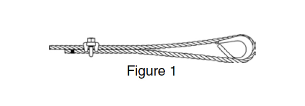
1. Refer to Table 1 in following these instructions. Turn back specified amount of rope from thimble or loop. Apply first clip one base width from dead end of rope. Apply U-Bolt over dead end of wire rope – live end rests in saddle (Never saddle a dead horse!). Use torque wrench to tighten nuts evenly, alternate from one nut to the other until reaching the recommended torque. (See Figure 1)

(a) Factor of Safety. All rope to be used for regular hoisting shall be wire rope providing a factor of safety not less than five to one for material hoist and ten to one for personnel hoist when new, which shall be calculated by dividing the breaking strength of the wire rope as given in the manufacturer"s published tables, by the total load to be hoisted including the total weight of the wire rope in the shaft when fully let out, plus a proper allowance for impact and acceleration.
(b) Wire Rope Fastenings. Every wire rope used for hoisting shall be securely fastened at both ends and when in use shall not be fully unwound; at least three full turns shall remain on the drum so as to protect the end fastening at drum from overload. The wire rope end at the cage, skip or bucket shall be securely fastened by a properly made tapered socket joint, by an eye in the wire rope made with an oval thimble and wire rope clips, or by another method acceptable to the Division for this or similar service. If the wire rope clip method is used, the spacing and number used shall be as shown in Table - 1 for U-Bolts and in Table - 2 for Fist-Grip clips based upon using RRL or RLL wire rope, 6 x 19 or 6 x 37 Class, FC or IWRC; IPS or XIP. If Seale construction or similar large outer wire type construction in the 6 x 19 Class is to be used for sizes 1 inch and larger, add one additional clip. If a pulley (sheave) is used for turning back the wire rope, add one additional clip.
The number of clips shown also applies to rotation-resistant RRL wire rope, 8 x 19 Class, IPS, XIP, sizes 1-1/2 inch and smaller; and to rotation-resistant RRL wire rope, 19 x 7 Class, IPS, XIP (sizes 1-3/4 inch and smaller for U-Bolts and size 1-1/2 inch and smaller for Fist Grips).
(d) Splicing. Spliced wire rope shall not be used, except that the end may be attached to the load by the thimble and/or clip method, as provided in subsection (b) of this section.
(1) A safety hook, shackle or other means providing closed design protection shall form the attachment between rope and a bucket, cage, skip or load. The attachment shall be made so that the force of the hoist pull, vibration, misalignment, release of lift force, or impact will not disengage the connection. Moused or open-throat hooks with light safety latches do not meet this requirement.
(2) All wire rope fittings and connections shall be in accordance with the manufacturers" specifications and compatible with the type of wire rope used.
(g) Drum Flanges. The drum of any hoist used for hoisting shall have flanges which extend at least 2 inches radially beyond the last layer of rope when all the rope is coiled on the drum.
Scope. This section applies to slings used in conjunction with other material handling equipment for the movement of material by hoisting, in employments covered by this part. The types of slings covered are those made from alloy steel chain, wire rope, metal mesh, natural or synthetic fiber rope (conventional three strand construction), and synthetic web (nylon, polyester, and polypropylene).
Employers must not use improved plow-steel wire rope and wire-rope slings with loads in excess of the rated capacities (i.e., working load limits) indicated on the sling by permanently affixed and legible identification markings prescribed by the manufacturer.
An eye splice made in any wire rope shall have not less than three full tucks. However, this requirement shall not operate to preclude the use of another form of splice or connection which can be shown to be as efficient and which is not otherwise prohibited.
Except for eye splices in the ends of wires and for endless rope slings, each wire rope used in hoisting or lowering, or in pulling loads, shall consist of one continuous piece without knot or splice.
Wire rope shall not be used if, in any length of eight diameters, the total number of visible broken wires exceeds 10 percent of the total number of wires, or if the rope shows other signs of excessive wear, corrosion, or defect.
Cable laid and 6 × 19 and 6 × 37 slings shall have a minimum clear length of wire rope 10 times the component rope diameter between splices, sleeves or end fittings.
Safe operating temperatures. Fiber core wire rope slings of all grades shall be permanently removed from service if they are exposed to temperatures in excess of 200 °F (93.33 °C). When nonfiber core wire rope slings of any grade are used at temperatures above 400 °F (204.44 °C) or below minus 60 °F (15.55 °C), recommendations of the sling manufacturer regarding use at that temperature shall be followed.
Wire rope slings shall have permanently affixed, legible identification markings stating size, rated capacity for the type(s) of hitch(es) used and the angle upon which it is based, and the number of legs if more than one.
Employers must not use natural- and synthetic-fiber rope slings with loads in excess of the rated capacities (i.e., working load limits) indicated on the sling by permanently affixed and legible identification markings prescribed by the manufacturer.
In manila rope, eye splices shall contain at least three full tucks, and short splices shall contain at least six full tucks (three on each side of the centerline of the splice).
In layed synthetic fiber rope, eye splices shall contain at least four full tucks, and short splices shall contain at least eight full tucks (four on each side of the centerline of the splice).
Strand end tails shall not be trimmed short (flush with the surface of the rope) immediately adjacent to the full tucks. This precaution applies to both eye and short splices and all types of fiber rope. For fiber ropes under 1-inch diameter, the tails shall project at least six rope diameters beyond the last full tuck. For fiber ropes 1-inch diameter and larger, the tails shall project at least 6 inches beyond the last full tuck. In applications where the projecting tails may be objectionable, the tails shall be tapered and spliced into the body of the rope using at least two additional tucks (which will require a tail length of approximately six rope diameters beyond the last full tuck).
Safe operating temperatures. Natural and synthetic fiber rope slings, except for wet frozen slings, may be used in a temperature range from minus 20 °F (-28.88 °C) to plus 180 °F (82.2 °C) without decreasing the working load limit. For operations outside this temperature range and for wet frozen slings, the sling manufacturer"s recommendations shall be followed.
Splicing. Spliced fiber rope slings shall not be used unless they have been spliced in accordance with the following minimum requirements and in accordance with any additional recommendations of the manufacturer:
In manila rope, eye splices shall consist of at least three full tucks, and short splices shall consist of at least six full tucks, three on each side of the splice center line.
In synthetic fiber rope, eye splices shall consist of at least four full tucks, and short splices shall consist of at least eight full tucks, four on each side of the center line.
Strand end tails shall not be trimmed flush with the surface of the rope immediately adjacent to the full tucks. This applies to all types of fiber rope and both eye and short splices. For fiber rope under 1 inch (2.54 cm) in diameter, the tail shall project at least six rope diameters beyond the last full tuck. For fiber rope 1 inch (2.54 cm) in diameter and larger, the tail shall project at least 6 inches (15.24 cm) beyond the last full tuck. Where a projecting tail interferes with the use of the sling, the tail shall be tapered and spliced into the body of the rope using at least two additional tucks (which will require a tail length of approximately six rope diameters beyond the last full tuck).
Removal from service. Natural and synthetic fiber rope slings shall be immediately removed from service if any of the following conditions are present:
Employers must use natural- and synthetic-fiber rope slings that have permanently affixed and legible identification markings that state the rated capacity for the type(s) of hitch(es) used and the angle upon which it is based, type of fiber material, and the number of legs if more than one.

This is in response to your letter dated February 4, 2003, to the Occupational Safety and Health Administration (OSHA). You ask for an interpretation of our fall protection standard §1926.502 (fall protection systems criteria and practices) regarding the use of U-bolt-type clamps. We apologize for the delay in providing this response.
Under Subpart M, is it permissible to use U-bolt-type clamps in the design of a wire rope horizontal lifeline attached to a billboard, with the saddle on the live side of the cable?
a supported scaffold consisting of a platform supported by brackets which are secured in place around the circumference or perimeter of a chimney stack, tank or other supporting structure by one or more wire ropes placed around the supporting structure.
…Where wire rope is used to secure brackets, U-bolt clips shall not be used because a segment of damaged dead end could later become part of the live end due to an increase in the circumference of the structure. By contrast, the standard allows U-bolts in other applications, such as where the U-Bolt is used at the end (dead end) of the wire rope and that part of the wire rope is never moved into the live section… [Emphasis added.]
As explained in the preamble to the scaffold standard, the reason this prohibition was included in the scaffold standard for repair bracket scaffolds was that the U-bolt clips often pinch and decrease the strength of the rope. Since repair bracket scaffolds must be expanded as the work progresses, the pinched (and weakened) part of the wire rope would eventually wind up in the "live end." This, then, was a concern that was specific to repair bracket scaffolds, and therefore the prohibition was included only for that type of scaffold.
As you indicated in your letter, there is no similar restriction on the use of U-bolt clips in Subpart M. As long as the strength and other criteria requirements in §1926.502 for horizontal lifelines are met, the U-bolt clips may be used. When rigged with the saddle side of the clip on the live (loaded) portion of the line, the pinching/damage will typically be limited to the dead end of the rope, and thus not decrease safety.
Note, though, that if you were to reconfigure the system after the clips had damaged part of the wire rope so that the damaged section became part of the "live end" of a horizontal lifeline, it is unlikely that you would be able to meet the strength requirements in §1926.502. Also, under §1926.502(d)(21):
If you need additional information, please contact us by fax at: U.S. Department of Labor, OSHA, Directorate of Construction, [Office of Construction Standards and Compliance Guidance], fax # 202-693-1689. You can also contact us by mail at the above office, Room N3468, 200 Constitution Avenue, N.W., Washington, D.C. 20210, although there will be a delay in our receiving correspondence by mail.
(a) Scope. This section applies to slings used in conjunction with other material handling equipment for the movement of material by hoisting, in employments covered by this Part. The types of slings covered are those made from allow steel chain, wire rope, metal mesh, natural or synthetic fiber rope (conventional three strand construction), and synthetic web (nylon, polyester, and polypropylene).
“Cable laid endless sling-mechanical joint” is a wire rope sling made endless by joining the ends of a single length of cable laid rope with one or more metallic fittings.
“Cable laid grommet-hand tucked” is an endless wire rope sling made from one length of rope wrapped six times around a core formed by hand tucking the ends of the rope inside the six wraps.
“Cable laid rope sling-mechanical joint” is a wire rope sling made from a cable laid rope with eyes fabricated by pressing or swaging one or more metal sleeves over the rope junction.
“Master link” or “gathering ring” is a forged or welded steel link used to support all members (legs) or an alloy steel chain sling or wire rope sling. (See Fig. N-184-3.)
“Strand laid endless sling-mechanical joint” is a wire rope sling made endless from one length of rope with the ends joined by one or more metallic fittings.
“Strand laid grommet-hand tucked” is an endless wire rope sling made from one length of strand wrapped six times around a core formed by hand tucking the ends of the strand inside the six wraps.
“Strand laid rope” is a wire rope made with strands (usually six or eight) wrapped around a fiber core, wire strand core, or independent wire rope core (IWRC).
Manufacturer of wire rope clips made from stainless steel and die-cast zinc materials. Grip and U-bolt clips are offered. Available in various wire rope diameters with drop forged, hot galvanized, self-colored and zinc plated finishes. Suitable for tillers and cables. Clips are also distributed. Serves the transportation, mining, railroad, construction, architectural, fitness, automotive, marine, OEM, military, display, signage, lighting, security and recreation industries. Some clips meet military specifications and are made in the USA.
Cable fall protection systems take many names, including rat lines, HLL’s, and horizontal lifelines just to name a few. In their simplest form, cable fall protection systems consist of wire rope secured by a series of terminal and intermediate anchor points. By connecting a body harness and lanyard to a shuttle traveling the length of the line, a worker can safely move along a horizontal (or vertical) plane. Cable systems are deceptively simple in design, but done properly, they are actually highly engineered fall protection systems.
In a previous post titled “Is My Horizontal Lifeline Safe?”, we shared pictures of some home-made rat lines we have encountered in the field. Lifelines made from combinations of wire rope, wire rope clips, and turnbuckles may look safe, but these home-made solutions share little in common with the engineered lifelines we design and install at DFP.
OSHA regulations say nothing about the materials required to build a lifeline, but do include specific language describing system performance in the event of a fall:
If you glean nothing else from the discussion above, it should be obvious that without an engineering background and fall protection training, the individual charged with designing and installing your home-made solution will not meet OSHA standards. Now that we have a better definition of the system, let’s turn to the advantages and disadvantages of cabled-based systems.

Rigging and safety gear purchased from Westech Rigging Supply should be used in strict accordance with all industry and OSHA standards. At no time should rigging or safety gear be used beyond its certified load ratings (aka Working Load Limits). Normal wear and tear should be expected with use of rigging and safety gear; therefore, all gear should be thoroughly inspected before each and every use. Worn or unsafe rigging and safety gear should never be used.


 8613371530291