
wire rope clips osha in stock

Wire rope is often used in slings because of its strength, durability, abrasion resistance and ability to conform to the shape of the loads on which it is used. In addition, wire rope slings are able to lift hot materials.
Wire rope used in slings can be made of ropes with either Independent Wire Rope Core (IWRC) or a fiber-core. It should be noted that a sling manufactured with a fiber-core is usually more flexible but is less resistant to environmental damage. Conversely, a core that is made of a wire rope strand tends to have greater strength and is more resistant to heat damage.
Wire rope may be manufactured using different rope lays. The lay of a wire rope describes the direction the wires and strands are twisted during the construction of the rope. Most wire rope is right lay, regular lay. This type of rope has the widest range of applications. Wire rope slings may be made of other wire rope lays at the recommendation of the sling manufacturer or a qualified person.
Wire rope slings are made from various grades of wire rope, but the most common grades in use are Extra Improved Plow Steel (EIPS) and Extra Extra Improved Plow Steel (EEIPS). These wire ropes are manufactured and tested in accordance with ASTM guidelines. If other grades of wire rope are used, use them in accordance with the manufacturer"s recommendations and guidance.
When selecting a wire rope sling to give the best service, consider four characteristics: strength, ability to bend without distortion, ability to withstand abrasive wear, and ability to withstand abuse.
Rated loads (capacities) for single-leg vertical, choker, basket hitches, and two-, three-, and four-leg bridle slings for specific grades of wire rope slings are as shown in Tables 7 through 15.
Ensure that slings made of rope with 6×19 and 6x37 classifications and cable slings have a minimum clear length of rope 10 times the component rope diameter between splices, sleeves, or end fittings unless approved by a qualified person,
Ensure that braided slings have a minimum clear length of rope 40 times the component rope diameter between the loops or end fittings unless approved by a qualified person,
Do not use wire rope clips to fabricate wire rope slings, except where the application precludes the use of prefabricated slings and where the sling is designed for the specific application by a qualified person,
Although OSHA"s sling standard does not require you to make and maintain records of inspections, the ASME standard contains provisions on inspection records.[3]
Ensure that wire rope slings have suitable characteristics for the type of load, hitch, and environment in which they will be used and that they are not used with loads in excess of the rated load capacities described in the appropriate tables. When D/d ratios (Fig. 4) are smaller than those listed in the tables, consult the sling manufacturer. Follow other safe operating practices, including:
When D/d ratios (see Fig. 6) smaller than those cited in the tables are necessary, ensure that the rated load of the sling is decreased. Consult the sling manufacturer for specific data or refer to the WRTB (Wire Rope Technical Board) Wire Rope Sling Users Manual, and
Before initial use, ensure that all new swaged-socket, poured-socket, turnback-eye, mechanical joint grommets, and endless wire rope slings are proof tested by the sling manufacturer or a qualified person.
Permanently remove from service fiber-core wire rope slings of any grade if they are exposed to temperatures in excess of 180 degrees F (82 degrees C).
Follow the recommendations of the sling manufacturer when you use metallic-core wire rope slings of any grade at temperatures above 400 degrees F (204 degrees C) or below minus 40 degrees F (minus 40 degrees C).
This responds to your June 1, 1999, letter to the Occupational Safety and Health Administration (OSHA), requesting information on wire rope and Crosby clips used around the perimeter of buildings as a guardrail. You also requested clarification on when employees must tie-off when a guardrail system is removed to facilitate hoisting operations. We apologize for the long delay in providing this response.
Question 1: How many Crosby clips are required to be used when setting up a wire rope guardrail? Is it permissible to splice two wire ropes by overlapping or must the connections be turned back into eyelets and properly secured?
Answer: For construction work covered by 29 CFR 1926 Subpart M, §1926.502(b) sets forth the criteria that must be met when using wire rope as a guardrail. The standard requires guardrails to meet several specific criteria. For example, 1926.502(b)(3) states that the guardrail shall be capable of withstanding, without failure, a force of at least 200 pounds applied within 2 inches of the top edge, in any outward or downward direction, at any point along the top edge. Section 1926.502(b)(4) states that when the 200 pound test load noted in §1926.502(b)(3) is applied in a downward direction, the top edge of the guardrail shall not deflect to a height less than 39 inches above the walking/working level. Section 1926.502(b)(9) states that the top rail and mid-rails shall be at least ¼-inch nominal diameter or thickness to prevent cuts and lacerations. These and other criteria must be met when using wire rope as a guardrail around the perimeter of a building.
The OSHA standard does not specify a minimum number of clips when using wire rope as a guardrail. However, as a practical matter, it is unlikely you could meet the specific requirements under §1926.502(b) unless you follow the manufacturer"s recommendations for the number of clips to be used on wire ropes of different diameters (for example, the Crosby Group Inc. general catalog, 2000 edition has tables showing their recommendations for their clips). Also, note that OSHA"s standard for rigging equipment used for material handling, 29 CFR §1926.251, has a table for the number of clips required for wire rope ½-inch and greater. Although that standard does not apply to wire rope used for guardrails, when you design a rope system to meet the §1926.502 requirements, following those tables will normally ensure that you have enough clips.
If you need additional information, please contact us by fax at: U.S. Department of Labor, OSHA, Directorate of Construction, Office of Construction Standards and Guidance, fax # 202-693-1689. You can also contact us by mail at the above office, Room N3468, 200 Constitution Avenue, N.W., Washington, D.C. 20210, although there will be a delay in our receiving correspondence by mail.

Scope. This section applies to slings used in conjunction with other material handling equipment for the movement of material by hoisting, in employments covered by this part. The types of slings covered are those made from alloy steel chain, wire rope, metal mesh, natural or synthetic fiber rope (conventional three strand construction), and synthetic web (nylon, polyester, and polypropylene).
Cable laid endless sling-mechanical joint is a wire rope sling made endless by joining the ends of a single length of cable laid rope with one or more metallic fittings.
Cable laid grommet-hand tucked is an endless wire rope sling made from one length of rope wrapped six times around a core formed by hand tucking the ends of the rope inside the six wraps.
Cable laid rope sling-mechanical joint is a wire rope sling made from a cable laid rope with eyes fabricated by pressing or swaging one or more metal sleeves over the rope junction.
Master link or gathering ring is a forged or welded steel link used to support all members (legs) of an alloy steel chain sling or wire rope sling. (See Fig. N-184-3.)
Diagram indicates Forms of Hitch and Kind of Sling. Eye&Eye Vertical Hitch. Eye&Eye Choker Hitch. Eye&Eye Basket Hitch (Alterates have identical load rations). Endless Vertical Hitch. Endless Choker Hitch. Endless Basket Hitch (Alternateve have identical load ratings). Notes: Angles 5 deg or less from the veritcal may be considered vertical angles. For slings with legs more than 5 deg off vertical, the actual angle as shown in Figure N-184-5 must be considered. Explanation of Symbols: Minimum Diameter of Curvature. Represents a contact surface which shall have a diameter of curvature at least double the diameter of the rope from which the sling is made. Represents a contact surface which shall have a diameter of curvature at least 8 times the diameter of the rope. Represents a load in a choker hitch and illustrates the rotary force on the load and/or the slippage of the rope in contact with the load. Diameter of curvature of load surface shall be at least double the diameter of the rope.
Strand laid endless sling-mechanical joint is a wire rope sling made endless from one length of rope with the ends joined by one or more metallic fittings.
Strand laid grommet-hand tucked is an endless wire rope sling made from one length of strand wrapped six times around a core formed by hand tucking the ends of the strand inside the six wraps.
Strand laid rope is a wire rope made with strands (usually six or eight) wrapped around a fiber core, wire strand core, or independent wire rope core (IWRC).
Sling use. Employers must use only wire-rope slings that have permanently affixed and legible identification markings as prescribed by the manufacturer, and that indicate the recommended safe working load for the type(s) of hitch(es) used, the angle upon which it is based, and the number of legs if more than one.
Cable laid and 6 × 19 and 6 × 37 slings shall have a minimum clear length of wire rope 10 times the component rope diameter between splices, sleeves or end fittings.
Safe operating temperatures. Fiber core wire rope slings of all grades shall be permanently removed from service if they are exposed to temperatures in excess of 200 °F. When nonfiber core wire rope slings of any grade are used at temperatures above 400 °F or below minus 60 °F, recommendations of the sling manufacturer regarding use at that temperature shall be followed.
Sling use. Employers must use natural and synthetic fiber-rope slings that have permanently affixed and legible identification markings stating the rated capacity for the type(s) of hitch(es) used and the angle upon which it is based, type of fiber material, and the number of legs if more than one.
Safe operating temperatures. Natural and synthetic fiber rope slings, except for wet frozen slings, may be used in a temperature range from minus 20 °F to plus 180 °F without decreasing the working load limit. For operations outside this temperature range and for wet frozen slings, the sling manufacturer"s recommendations shall be followed.
Splicing. Spliced fiber rope slings shall not be used unless they have been spliced in accordance with the following minimum requirements and in accordance with any additional recommendations of the manufacturer:
In manila rope, eye splices shall consist of at least three full tucks, and short splices shall consist of at least six full tucks, three on each side of the splice center line.
In synthetic fiber rope, eye splices shall consist of at least four full tucks, and short splices shall consist of at least eight full tucks, four on each side of the center line.
Strand end tails shall not be trimmed flush with the surface of the rope immediately adjacent to the full tucks. This applies to all types of fiber rope and both eye and short splices. For fiber rope under one inch in diameter, the tail shall project at least six rope diameters beyond the last full tuck. For fiber rope one inch in diameter and larger, the tail shall project at least six inches beyond the last full tuck. Where a projecting tail interferes with the use of the sling, the tail shall be tapered and spliced into the body of the rope using at least two additional tucks (which will require a tail length of approximately six rope diameters beyond the last full tuck).
Removal from service. Natural and synthetic fiber rope slings shall be immediately removed from service if any of the following conditions are present:

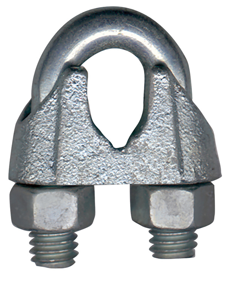
Bishop Lifting stocks 3 styles of Forged Wire Rope Clips for use as Wire Rope end Fittings. G-450 Red-U-Bolt® Clips, G-429 Fist Grip Clips and G-460 Soft Eye Bundle Clip, and the G-461 Thimble Eye Bundle Clip. Bishop Lifting is a proud distributor for the Crosby group including their line of wire rope clips.
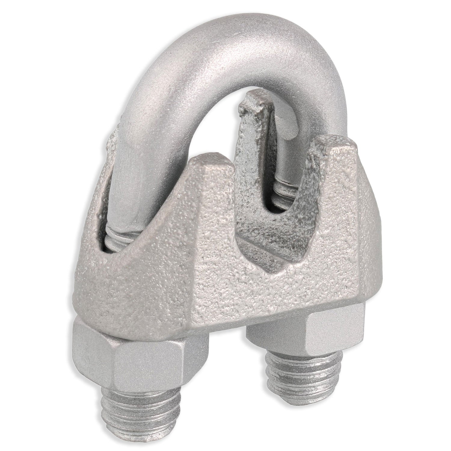
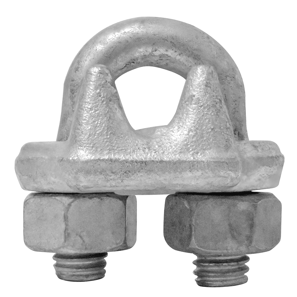
Wire Rope Clips are used for forming eyes in the ends of wire rope by following an installation procedure provided by Crosby® and OSHA 1926.251. ASME states that when used for lifting wire rope clips shall be drop-forged steel of single saddle (u-bolt) or double saddle clip. Malleable cast iron wire rope clips shall not be used. The use of wire rope clips to fabricate slings is generally prohibited as per ASME B30.9. Efficiency ratings of a properly prepared loop or thimble eye terminations for clip sizes 1/8" through 7/8" is 80%, and sized 1" through 3-1/2" is 90%. U-Bolt style clips are not recommended for elevator, personnel hoist and scaffold applications, refer to ANSI A17.1 and ANSI A10.4. Consult the manufacturer before installing wire rope clips on plastic coated or plastic impregnated wire rope.
Before installing the wire rope clips make sure that you have the proper size clips and that the turnback is the proper length based on manufacturer"s recommendations. Place the wire rope clips on in the proper sequence, and make sure that you torque all of the wire rope clips evenly. The saddle of the wire rope clip should be placed on the live end of the wire rope, and the u-bolt should be placed on the dead end. Make sure that you use at least the minimum number of wire rope clips, proper spacing, and turnback length recommended by the manufacturer. Also make sure you torque the wire rope clips to the torque values recommended by the manufacturer. After assembly make sure that you test the connection to at least the anticipated working load, and the check and retighten the wire rope clips to the recommended torque values.
Crosby wire rope clips can be reused if they were installed properly and can pass inspection in between uses. Wire rope clips will wear out over time when they are reused. Check the threads for stretch and corrosion and check the saddle area for wear, deformation, and corrosion. The u-bolt must fit into the base without requiring a forceful change in u-bolt spread. The wire rope clip assembly must be properly installed and capable of being torqued to the proper values. The roddles (ridges) in the clip base must be undamaged, and the clip assembly must be retorqued after the initial load application to the specified torque values.
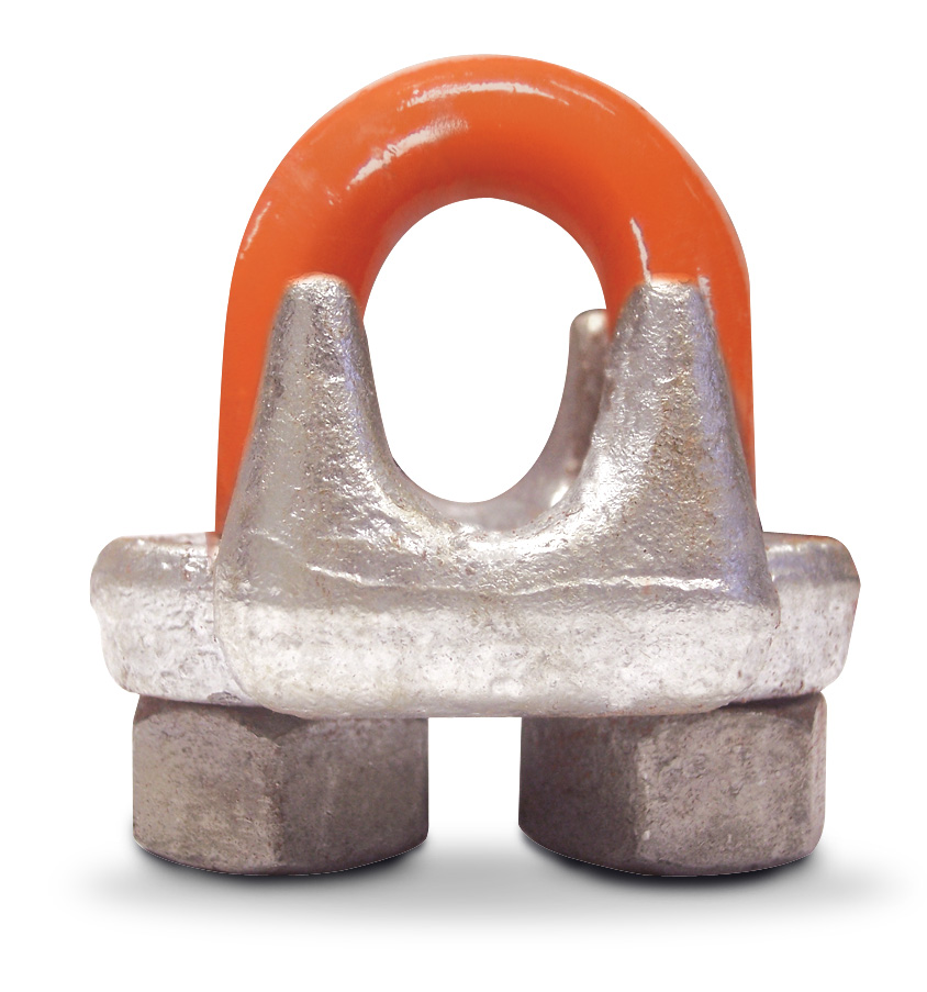
G-460 Soft Eye Bundle Clip and G-461 Thimble Eye Bundle Clips are used to hold pre-slinged choker eyes in position. These Bundle Clips reduce the rigging and handling time of drill pipe, casing and other down hole tubulars at shore bases, supply vessels and offshore installations.

Wire Rope Clips can have lots of helpful uses – they are a simple fitting that can be easily used in the field or shop. Sometimes called a u-bolt or u-bolt clip, they can be used to join two wire rope ends together, make an eye for a pulling application, or to secure the loose end of a wire rope after a wedge socket (or other appropriate device) has been used to terminate a crane’s hook.
But using clips to create wire rope slings for overhead lifting is NOT one of their many uses. Did you know that not only is it a poor rigging practice to fabricate slings in this manner, in the U.S. it is against the law?
ASME B30.9 states that wire rope clips shall not be used to fabricate wire rope slings, except where the application of slings prevents the use of prefabricated slings.
ASME B30.9 states wire rope clips shall be drop-forged steel of single saddle (u-bolt) or double saddle clip. Malleable cast iron clips shall not be used.
Why these restrictions? Wire rope clips diminish the working load limit of the wire rope to generally about 70-75% of its original strength.There are better and more efficient ways to fabricate slings for overhead lifting.
For situations where use of wire rope clips are approved, it’s important to remember the proper way to install the clips. Incorrect installation can reduce the working load limit by 40% or more. The easiest thing is to remember, “never saddle a dead horse.”
The saddle of the clip is the piece that the U bolt fits into. The dead end of a wire rope is the end of the eye that contains the cut side. The U bolt should always be in contact with the dead end, while the saddle should be on the live end.
In addition, for clips to work properly and gain their design efficiency, the proper number of clips is required and the nuts must be torqued as prescribed by the manufacturer. For more information on proper installation, check out this video from the Crosby Group.
If you have more questions on wire rope clips, comment below. Remember that Safety through Education is more than just our motto, it is our guiding principle. If you need training on proper application on any other rigging hardware, reach out to us. We are here for you.

Cable guardrails are commonly seen on construction projects. Although they can provide adequate protection at perimeter edges, they often have issues with the way they are installed. Risk Managers should keep the below in mind to share with their workers and safety committees. If properly constructed and maintained, cable guardrails can provide compliant fall protection in numerous situations.
Typically, cable guardrails are erected by ironworkers at the final interior and exterior perimeters of floors upon completion of installing the deck. However, cast-in-place concrete structures may transition from wood guard rails to cable guardrails installed by carpenters. As part of the floor turnover process for a steel or concrete building, controlling contractors often times direct the contractor who installed the system to leave the perimeter cables in place until the fall exposure is removed by setting windows or curtain wall. At this point, the controlling contractor inspects and accepts control of the fall protection if it meets the following criteria set forth by OSHA 1926 Subpart M regulations:
It is highly recommended anyone who installs or maintains safety cables be trained and authorized. These systems are initially compliant, but when tampered with or removed by others throughout the course of construction and not replaced properly, they can be a safety concern.
Excessive Deflection or Sagging – incorporate turnbuckles to allow for easy tightening of the cable. Another option is to keep a cable puller and wire rope grip attachment handy in order to tighten cable guardrails easily.
System Not Properly Terminated – common issues include wire rope clips installed backwards, not enough wire rope clips, and the cables are improperly spliced. The U-Bolt of the clip should be applied to the dead end of the wire rope and the saddle on the live end. This is what the phrase,“Never saddle a dead horse!” refers to. There should be at least two clips installed for wire rope that is ¼” – 3/8” in diameter. Lastly, the preferred method to terminating the wire rope or splicing two wire ropes together is to turnback the ends through each eye as seen in the diagrams.
An alternative method to splicing two wire ropes together is to lay the wire rope ends parallel and correctly apply the proper amount of wire rope clips as depicted in the diagrams.
Safety cable guardrails can provide OSHA compliant fall protection for employees on a construction project. However, they must be continuously inspected and maintained to ensure compliance with OSHA 1926 Subpart M standards.

Delta Rigging and Tools stocks 3 styles of Forged Wire Rope Clips for use as Wire Rope end Fittings. G-450 Red-U-Bolt® Clips, G-429 Fist Grip Clips and G-460 Soft Eye Bundle Clip, and the G-461 Thimble Eye Bundle Clip.
Wire Rope Clips are used for forming eyes in the ends of wire rope by following an installation procedure provided by Crosby® and OSHA 1926.251. Efficiency ratings of a properly prepared loop or thimble eye terminations for clip sizes 1/8" through 7/8" is 80%, and sized 1" through 3-1/2" is 90%. U-Bolt style clips are not recommended for elevator, personnel hoist and scaffold applications, refer to ANSI A17.1 and ANSI A10.4.
G-460 Soft Eye Bundle Clip and G-461 Thimble Eye Bundle Clips are used to hold pre-slinged choker eyes in position. These Bundle Clips reduce the rigging and handling time of drill pipe, casing and other down hole tubulars at shore bases, supply vessels and offshore installations.
Efficiency ratings for wire rope end terminations are based upon the minimum breaking force of wire rope. The efficiency rating of a properly prepared loop or thimble-eye termination for clip sizes 1/8” through 7/8” is 80%, and for sizes 1” through 3-1/2” is 90%.
The number of clips shown (see Table 1) is based upon using RRL or RLL wire rope, 6 x 19 or 6 x 36 Class, FC or IWRC; IPS or XIP, XXIP. If Seale construction or similar large outer wire type construction in the 6 x 19 Class is to be used for sizes 1 inch and larger, add one additional clip. If a pulley (sheave) is used for turning back the wire rope, add one additional clip.
The number of clips shown also applies to rotation-resistant RRL wire rope, 8 x 19 Class, IPS, XIP, XXIP sizes 1-1/2 inch and smaller; and to rotation-resistant RRL wire rope, 19 x 7 Class, IPS, XIP, XXIP sizes 1-3/4 inch and smaller.
For elevator, personnel hoist, and scaffold applications, refer to ANSI A17.1 and ANSI A10.4. These standards do not recommend U-Bolt style wire rope clip terminations. The style wire rope termination used for any application is the obligation of the user.
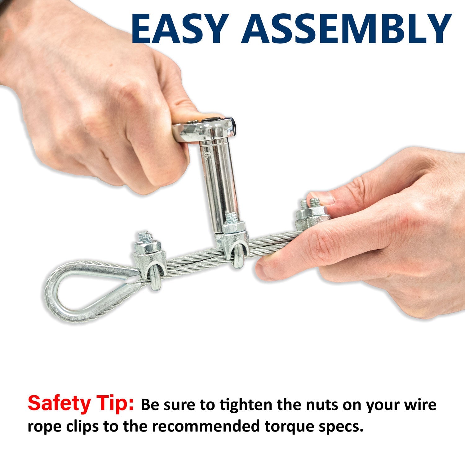
Turn back specified amount of rope from thimble or loop. Apply first clip one base width from dead end of rope. Apply U-Bolt over dead end of wire rope – live end rests in saddle (Never saddle a dead horse!). Use torque wrench to tighten nuts evenly, alternate from one nut to the other until reaching the recommended torque. (See Figure 1 below)
Use torque wrench to tighten nuts evenly, alternating until reaching the recommended torque. When more than two clips are required, apply the second clip as near the loop or thimble as possible, turn nuts on second clip firmly, but do not tighten. (See Figure 2 below)
Space additional clips equally between first two – take up rope slack – use torque wrench to tighten nuts on each U-Bolt evenly, alternating from one nut to the other until reaching recommended torque. (See Figure 3 below)
The preferred method of splicing two wire ropes together is to use inter-locking turnback eyes with thimbles using the recommended number of clips on each eye (See Figure 5 below).
An alternate method is to use twice the number of clips as used for a turnback termination. The rope ends are placed parallel to each other, overlapping by twice the turnback amount shown in the application instructions. The minimum number of clips should be installed on each dead end (See Figure 6 below). Spacing, installation torque, and other instructions still apply.
Apply first load to test the assembly. This load should be of equal or greater weight than loads expected in use. Next, check and use torque wrench to retighten nuts to recommended torque. In accordance with good rigging and maintenance practices, the wire rope end termination should be inspected periodically for wear, abuse, and general adequacy.
Mechanical Splice and Hand Splice, all slings are made from 6 x 19 EIP wire rope and tested to required load limits. As per OSHA requirements, each wire rope sling has a tag woven into the wire showing the required date and location of manufacture, the dimensions and load limits.
Wire rope clips, sometimes referred to as u bolt clamps, u bolt clips, u clips, u clamps or cable clamps, are used to secure the loose end of a wire rope when forming an eye. Wire rope u clips have a u-bolt that is secured into a saddle by two nuts. Wire rope assemblies almost always require two, or more wire rope clamps to secure the wire rope properly. When using wire rope cable clamps to form an eye in a wire rope, the working load limit of the wire rope is reduced by about 20%.
Here at Tri-State Rigging Equipment we pride ourselves on providing only the highest quality wire rope clamps from only the most reputable manufacturers. We can provide you with any wire rope clip on the market so, if you are unable to find what you are looking for, or if you don’t know exactly what you need, call or email our sales team to speak with a rigging product specialist.
Wire rope cable clamps come in a variety of materials ranging from galvanized and zinc plated steel, to stainless steel. The two most important different types, however, are drop forged and malleable wire rope u bolt clips.
Drop forged wire rope clips are more heavy duty than malleable rope clips and can therefore be used for more heavy-duty rigging applications. In addition, they are galvanized with a heavy coating of zinc that resists the corrosion and abuse found in rugged work environments. Wire rope cable clamps of every type are not designed to be used in an overhead lift but drop forged wire rope u bolt clamps can be used to suspend an overhead load. This makes wire rope cable clamps ideal for use with:
Regarding the first question, if the load is being moved, wire rope clips are not to be used. If the load is being held in place, heavy-duty drop forged wire rope clips can be used. For the second question, if the load is near the ground, malleable wire rope clips may be used, as their lighter duty design is more than enough for the job. On the other hand, if the load is being suspended above the ground, heavier duty drop forged wire rope clamps must be used.
In the rigging and lifting industry there is a common saying that is used to remember the correct way to use wire rope u clips: “Never saddle a dead horse.” This means that the saddle of the u clamp should always be in contact with the live side of the wire rope rather than the dead side. The dead side of the wire rope is the side of the eye that has the cut end. The dead end is attached to the live end of the wire rope to form an eye and it is imperative that the saddle be on the live side of the wire rope.
Tri-State Rigging Equipment is a service provider and distributor for all wire rope cable clamps, and u bolt clips for rigging serving clients from coast to coast, Canada, Mexico and especially focused in the states of Missouri, Illinois, Indiana, Iowa, Kansas, Nebraska, Arkansas, Mississippi, Tennessee, Kentucky, South Carolina, Florida, and Oklahoma.
(a) Scope. This section applies to slings used in conjunction with other material handling equipment for the movement of material by hoisting, in employments covered by this Part. The types of slings covered are those made from allow steel chain, wire rope, metal mesh, natural or synthetic fiber rope (conventional three strand construction), and synthetic web (nylon, polyester, and polypropylene).
“Cable laid endless sling-mechanical joint” is a wire rope sling made endless by joining the ends of a single length of cable laid rope with one or more metallic fittings.
“Cable laid grommet-hand tucked” is an endless wire rope sling made from one length of rope wrapped six times around a core formed by hand tucking the ends of the rope inside the six wraps.
“Cable laid rope sling-mechanical joint” is a wire rope sling made from a cable laid rope with eyes fabricated by pressing or swaging one or more metal sleeves over the rope junction.
“Master link” or “gathering ring” is a forged or welded steel link used to support all members (legs) or an alloy steel chain sling or wire rope sling. (See Fig. N-184-3.)
“Strand laid endless sling-mechanical joint” is a wire rope sling made endless from one length of rope with the ends joined by one or more metallic fittings.
“Strand laid grommet-hand tucked” is an endless wire rope sling made from one length of strand wrapped six times around a core formed by hand tucking the ends of the strand inside the six wraps.
“Strand laid rope” is a wire rope made with strands (usually six or eight) wrapped around a fiber core, wire strand core, or independent wire rope core (IWRC).


 8613371530291