
wire rope diameter measurement factory
Rope diameter is specified by the user and is generally given in the equipment manufacturer’s instruction manual accompanying the machine on which the rope is to be used.
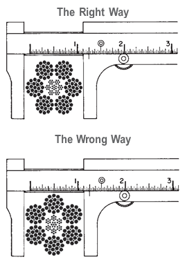
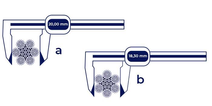
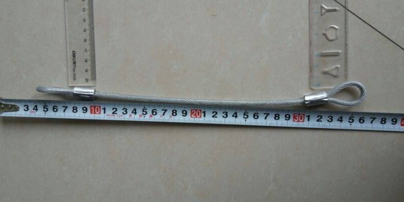
Rope diameters are determined by measuring the circle that just touches the extreme outer limits of the strands— that is, the greatest dimension that can be measured with a pair of parallel-jawed calipers or machinist’s caliper square. A mistake could be made by measuring the smaller dimension.

As already discussed on the ‘Measuring the rope diameter‘ page and on the ‘Break-In-Period‘ page, shortly after installation, the wire rope diameter will slightly decrease. This is normal and is caused by the adjustment of all rope elements when loaded the first time. To evaluate the diameter reduction, you have to measure the rope when new, and you also have to measure the rope after the break in period at a specified load. This gives you a good indication of the magnitude of the initial diameter reduction in your specific application. The diameter reading you took after the break in period should now become your ‘gauge’. Do not compare the rope diameter you are about to take with the ‘catalogue’ diameter. It may give you a false indication, since wire rope may have a plus tolerance of up to 4% to 5% over the ‘catalogue’ diameter.
If you detect a further diameter reduction when measuring the rope under the same load condition as after the break in period, it is often due to excessive abrasion of the outside wires, loss of core support, internal or external corrosion, inner wire failures, and/or inner wire abrasion. However, there will always be a normal continuous small decrease in diameter throughout the rope’s service life.
Deciding whether or not a rope is safe is not always a simple matter. A number of different but interrelated conditions must be evaluated. It would be dangerously unwise for an inspector to declare a rope ‘safe’ for continued service simply because its diameter had not reached a certain minimum diameter if, at the same time, other observations led to a different conclusion.
However, ASME, ISO 4309, CSA, other Canadian Provincial H&SA and USA OSHA Regulation have various values published for maximum allowable diameter reductions. They are somewhat confusing as they show diameter reduction values from 3.5% to 9%, and some give reduction values in inch fractions depending on rope nominal diameter.
The amount of yarn per metre is accurately calculated and strictly controlled to produce a finished rope with the correct interacting tension (or lay) at a nominal diameter, normally in 2mm increments in even numbers e.g. 8mm, 10mm, 12mm
Importantly, the final break load of the rope for any given diameter is dependent on the quantity/weight of yarn per metre in the designated construction.
Rope manufacturers publish minimum (or average) break loads for their ropes and therefore all rope production is designed to achieve this rather than concentrating solely on the finished diameter.
Attempting to measure the diameter of a new rope - by eye, with a tape measure or even callipers - before it has stretched out to a working diameter isn"t likely to produce an accurate result.
The true diameter will be more apparent if you hold the rope firmly with one hand, take a firm grip with the other hand and run the rope through your grip without releasing the pressure - a leather glove will protect your hand if required.
Once you have used your new rope, and applied a light load, the interacting weave or lay will elongate to the manufacturer designed structure i.e. it will naturally become slightly thinner and consequently slightly longer. The effect varies across all ropes due to the complex variation of two factors: the construction of the rope and the elasticity of the fibre. This should result in your rope measuring more closely to the nominal diameter.
The amount that it relaxes also depends on the construction of the rope - a closer, tighter weave is generally less affected e.g. 32 plait and conversely, a looser construction will be more affected e.g. 3 strand and 8 strand
Jimmy Green Marine began selling rope in 1981, over 40 years ago, and very quickly realised that customers wouldn"t always appreciate the finer points of rope construction.
We therefore allow for the concertina effect when measuring your order by adding an appropriate percentage according to the elasticity of the rope i.e. the stretchier it is, the more we add on to compensate.

For all wire rope, the best time to begin taking appropriate care and handling measures, is immediately upon receiving it. On arrival, the rope should be carefully checked to make certain that the delivered product matches the description on tags, requisition forms, packing slips, purchase order and invoice.
After these necessary preliminary checks, the next concern is that of providing weather-proof storage space. If wire rope is to be kept unused for a considerable time, it must be protected from the elements. The ideal storage area is, a dry, well-ventilated building or shed. Avoid closed, unheated, tightly sealed buildings or enclosures because condensation will form when warm, moist outside (ambient) air envelops the colder rope. Although wire rope is protected by a lubricant, this is not totally effective since condensation can still occur within the small interstices between strands and wires, thereby causing corrosion problems.
On the other hand, if the delivery site conditions preclude storage in an inside space and the rope must be kept outdoors, it should be effectively covered with a waterproof material. Moreover, weeds and tall grass, in the assigned storage area, should be cut away; the reel itself should be placed on an elevated platform that will keep it from direct contact with the ground. Providing an adequate covering for the reel also prevents the original lubricant from drying out and thereby losing its protection.
Never store wire rope in areas subject to elevated temperatures. Dust and grit, or chemically laden atmospheres, are also to be avoided. Although lubricant applied at the factory offers some degree of protection, every normal precautionary measure should be taken with every coil or reel of wire rope.
Whenever wire rope remains in position on an idle machine, crane, hoist, etc., it should be coated with an appropriate protective lubricant. In these circumstances, as with ropes stored outside, moisture, in the form of condensation, rain or snow may form on the wire rope. Some of the moisture may easily become trapped inside the rope and cause corrosion problems.
If the wire rope is to be kept inactive for an extended period while wound on the drum of the idle equipment, it may be necessary to apply a coating of lubricant to each layer as the rope is wound on the drum. Cleaning, inspection and re-lubrication should precede start-up of the equipment.
The actual diameter of a wire rope is the diameter of a circumscribed circle that will enclose all the strands. It ‘s the largest cross-sectional measurement as shown here. You should make the measurement carefully with calipers.
As we move toward metric measurements, it will become increasingly necessary to convert English units into Sl – International System of Units – (or metrics), and vice versa.
For standard, general purpose wire ropes, in measuring diameter, the industry is leaning toward a “soft” conversion to metric during the transition period. For example, a 1″ diameter rope converts to 25.4 mm in metrics. Using the soft conversion, this is changed to the whole metric size that most nearly parallels the 1″ size range, or 26 mm. In sizes smaller than 5/8′: the rope diameter is rounded to the nearest 0.5 mm.
The following table gives the closest equivalent metric diameters for rope sizes up through 5 inches. Again , these metric sizes are based on the industry’s “soft” conversion. Your application may have tighter tolerances that require a hard conversion. Therefore, the values in the table would not apply.
Since rope minimum breaking force and weight per unit of length vary for different types and grade of ropes, the following conversion factors are given to help you convert the figures you need:
Note: The newton (a unit of force) is the correct unit for measurement of minimum breaking force in the Sl system of units. We have included a conversion f
There are many different sizes, configurations, and materials that form wire rope, and these are different types including stainless steel wire rope, galvanized wire rope, and bright wire rope.
Looking for accessories to use with wire ropes? Our rigging supplies include hardware and accessories for use with cranes, hoists & winches, and oilfield applications.
Diameter:To properly measure the diameter of steel wire ropes, measure the rope at its widest point. This is an industry standard with wire cable manufacturers and steel cable suppliers.
Grade of Steel – EIPS, EEIPS: EIPS is Extra Improved Plowed Steel and has roughly 10% more strength than IPS. EEIPS is Extra Extra Improved Plowed Steel and is approximately 10% stronger than the EIPS. We offer every variety of EIPS Wire Rope and have a one day lead time on any EEIPS ropes.
Direction of Lay: Right hand and left hand designates which way the strands wrap around the core of the steel rope. Regular lay and Lang lay specify which way the wires are formed in the helix pattern. Regular lay means the wires are rotated opposite the direction of the strands around the core. Lang lay means the wires are twisted in the same direction as the strands are wrapped around the wire rope core.
Finish – Bright Wire, Galvanized Wire, and Stainless Steel: Most wire ropes have a bright, self-colored finish hence the name. Wire ropes generally have a coating of lubricant to reduce friction and protect from corrosion. However, there are wire ropes that are galvanized, stainless steel, or coated in vinyl and other plastics.
Material of the Core: Fiber Core (FC) or Independent Wire Rope Core (IWRC) – Fiber cores are made of natural (sisal, etc.) or synthetic (polypropylene, etc.) fibers and allow for increased flexibility. IWRC offers more support to the outer strands, and have a higher resistance to crushing. IWRC also offers more resistance to heat, reduces the amount of stretch, and increases the strength of the rope.
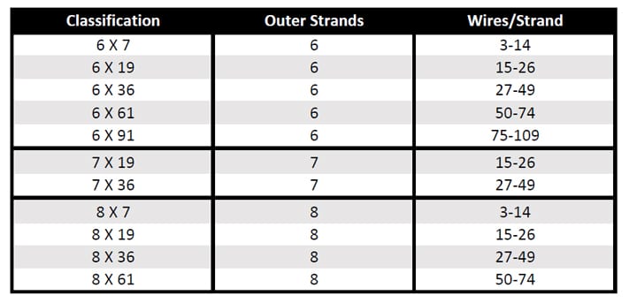
Strands: Another variable in wire rope is how many strands make up the rope and how many wires make up one strand. For instance, a 6×26 wire rope has 6 strands around a core with 26 wires making up each strand. The 6×19 class is the most common and offers higher resistance to abrasion whereas the 6×37 class offers higher flexibility.
Although there are exceptions for special applications, the constructions in 6×36 classification are primarily designed to be the most efficient for each rope diameter. As the rope size increases, for instance, a large number of wires can be used to achieve required fatigue resistance, and still those wires will be large enough to offer adequate resistance to abrasion.
The 6×19 classification of wire ropes includes standard 6 strand, round strand ropes with 16 through 26 wires per strand. This is a good rope to withstand abrasion or crushing on the drum. Ropes with independent wire rope strands and a core (IWRC) in general, are more crush resistant than fiber core ropes.
When you purchase our 6×19 Class of wire ropes, you get more than just another rope. Manufactured in an ISO 9001 certified factory and backed by the industry’s largest staff of professional engineers, we do more than meet published specifications.
The 6×26 WS has better resistance to abrasion than a 6x25FW. It features a compact construction with solid support for the wires; therefore it has a high resistance to crushing. Its number and relative size of the inner wires add to the stability of the strand and gives it a fatigue resistance comparable to a 6×25 FW. A standard 6×26 WS construction provides the best rope for a wide range of applications. In general, we recommend the use of the 6x26WS in any application where a 6x25FW is used.
Mast Raising Lines, also called Bull Lines or Bridle Lines, are usually two pieces: each having sockets on both ends. These lines can be fabricated from either right regular lay rope or right lang lay rope. They must be fabricated from IWRC ropes.
Premium ropes may be used for specific applications. PFV cushions the strands, distributes internal stresses, keeps in wire rope lubricant and keeps out dirt and debris, extending the service life.
Flex-X® 9 features compacted strands and swaging for extra drum crushing resistance and increased stability. Its high-density strands deliver extra strength and resistance to abrasion. Flex-X® 9 is manufactured with a dual compaction process to produce a compact cross-section with minimum voids and greater surface area on outer wires that contact drums, sheaves and the rope, itself during operation. The high-density compacted strands minimize nicking at strand-to-strand contact points. Flex-X® 9 was specifically designed for boom hoist applications and tubing line applications where drum crushing is a challenge.
Flex-X® 6 users receive superior performance and increased service life in many applications compared to the ropes they had previously employed. When compared to conventional six-strand ropes, Flex-X® 6 ropes provide greater surface area and more steel per given diameter. This increases rope stability and strength. This results in a longer service life and less sheave and drum wear.
Flex-X® 19, a Category 2 rotation resistant rope, is made from 19 strands. Six strands are laid around a core strand in one direction, and then 12 strands are laid around this first operation in the opposite direction. Because of its tightly compacted smooth design, Flex-X® 19 offers more crushing resistance than standard 19×7 rope, higher strength-to-diameter, resistance to bending fatigue, exceptional stability, reduced wear to sheaves and drums, and improved handling, operating and spooling characteristics.

Rope diameter is normally specified by the user or given in instruction manuals accompanying the customers" machine. So measuring the accurate diameter of steel wire ropes becomes extremely important for our customer to provide correct numbers. We believe the following instruction will give your some guidance:Before you start measuring, check your parallel-jawed caliper is operating well.

Wire ropes are largely used in marine environment or for rigging purposes. They receive considerable loads and thus suffer a great deal of mechanical damage throughout their service life. Moreover, research has shown that the major cause of wire rope failure is excessive deterioration and corrosion, lack of maintenance and inspection, and wrong usage resulting in early discarding, reduced safety and replacement cost increase.
Sometimes damage can be easily detected, while in other cases fractured wires may occur on the inside. Hence, wire ropes should be inspected and maintained by the right person (competent person assigned by the company), to assure they’re in perfect condition. Regular inspectionsensure high rope performance, long service lifetime , safety of personnel and equipment, and reduced operating costs.
All ropes (synthetic, high modulus and wire ropes) should be inspected before and after an operation. This guideline ensures maximum safety for both a ship’s personnel and equipment. Even though it’s difficult to determine the exact service life span of ropes, there is a way to have a more precise estimation about their efficient lifecycle. Calculating the exact time ropes have been in use (e.g mooring time, mooring conditions, weather and tidal conditions) is the answer. All in all, rope inspections should occur at least once a year.
Inspecting wire ropes in particular, comes with great responsibility. Inspection results should be recorded, and any defects noticed have to be reported and addressed properly. Some defects can be repaired, while in some cases replacing a wire rope is inevitable.
Periodical inspections ofvessel deck equipment is also crucial for maintaining the good condition of wire ropes. The condition of the drum, chocks, bitts, rollers, sheaves, cable clamps and other end fittings, affect the rope’s performance, threads and cords. Make sure to mark these parts during your overall inspection.
In order to help marine officers and staff conduct successful wire rope inspections – and keep an up-to-date record of them – we have created an inspection solution that helps in maintaining and monitoring a ship’s ropes and deck equipment.
When calculating mass using F = Minimum Breaking Force, according to the wire rope’s diameter, you can determine the Minimum Breaking Massand therefore the wire’s max strength. When calculating mass using F = Safe Load according to the wire rope’s diameter, you can determine the Safe Load Mass,which is the advised load for this rope diameter.
The strands of a wire rope absorb the majority of the tensile force applied on the rope. Their design and manufacturing standards affect the level of fatigue resistance and resistance to abrasion. An easy way to understand which rope design is suitable for each purpose, is the wire rope classification.
Wire ropes are classified according to the number of strands in each construction and the number of wires in each strand. For example, a classification of 6X19 means that a wire rope of this type always has six strands, but its wires could be 15-26 per strand. This is because 19 is not the exact number of wires, but the classification of a wire number range.
Visual inspections are a common and fast way to assess wire rope condition. Both the standard and rotation resistant wire rope inspectionprocesscomply with the same four steps of examination. A ship’s crew can perform them as follows:
Steel wire rope distortion is obvious in most cases and can easily be identified by the inspector or the ship‘s crew. It usually occurs if load is suddenly applied or abruptly released (shock loading), or even if swift torque is forcefully induced.
Although not all of these deformations make the rope absolutely dangerous to use, they all may cause ropes to wear unevenly in time. This means inspections should take place more often, and distorted ropes should be handled with caution.
The rag and visual inspection is a good method for regular inspection intervals. The inspector pulls a rag along the rope trying to find broken wire cords. If the rug gets snagged by the rope, the inspector has to stop and assess the wire rope’s condition. Extreme caution should be exercised during the visual inspection, and under no circumstances should this method be the only one used to inspect wire ropes.
Tip: When you encounter a protruding wire end, bend it back and forth manually, until it separates from the wire. This will protect neighboring wires from wearing out.
Diameter reduction is a critical factor in steel wire rope wear and if not properly taken care of, it can result in rope breakage. Excessive abrasion, loss of core mass, corrosion or inner wire failure are all factors that contribute to diameter reduction.
To get an accurate measurement of the rope’s diameter, measure the rope at three different points at least 5 feet apart. Take the average of these three measurements to determine the true diameter.
Any measurements showing a reduction of ⅓ or more, indicate that a replacement should follow without delay. A diameter reduction of less than 1/3 still requires attention, and the inspector or the ship’s crew should be on guard in the next scheduled wire rope inspection.
Failure from abrasion or corrosion is a result of deficient deck equipment inspection or insufficient wire rope lubrication respectively. Internal corrosive damage is more difficult to identify than any other types of degradation. In most cases, the damage has progressed more than the external signs suggest.
Wire rope storage plays a significant role in the rope’s operation life.Wire rope corrosion and pitting can be avoided if ropes are safely stored in a clean, cool, dry and well-ventilated place. Steel wire ropes should not by any means rest on the floor, and should be protected from water, dust or any chemical fumes. Long term storage requires periodic greasing, turning the reel upside down for preventing grease dripping and possibly re-winding to another reel with larger inner tube diameter.
Wire ropes should be maintained with periodical lubrication. In order to prevent internal corrosion, a pressure lubricator is suggested to be used. In this case, a small amount of grease is used to lubricate the rope internally, while the deck stays grease-clean. Pressure lubricators clean the rope before they grease it so that the new grease enters a clean rope. The type of grease used is very important for maximum protection and greasing efficiency.
Steel wire ropes exposed to dirt, grime and other contaminants, have to be cleaned with a wire brush and petroleum (unless a pressure lubricator is used). Optimal cleaning of wire ropes can extend their service life and guarantee safe operations.
The reeling process is of high importance for the longevity of wire ropes. To protect them from being damaged, it is important that the surface of the drum is clean, smooth and dry. Improper reeling may cause wire-rope strands to spread or get flattened, when in contact with one another, as successive layers are being spooled and upper layers apply pressure on the lower ones.
Katradis S.A. offers a wide range of top quality wire ropes for shipping (mooring and hoisting operations), fishing and construction purposes. Our wire ropes have greater resistance to fatigue, and they distribute tension force equally among the rope strands. They are less likely to kink, providing higher staff safety and assuring operation success.
Wire rope diameter // Measuring Devices and their correct handling // Types of measuring devices // Lay direction of a wire rope // Rope design // Fill factor of a rope // Lay types of wire ropes // Low-tension wire ropes // Types of rope cores (abbreviated designations according to EN 12385-2) // Semi rotation-resistant wire ropes // Rotation-resistant wire ropes // Wire rope lubricant & Re-lubrication
All wires in the assembly process are assembled with the aid of jigs, so the fitting of ferrules, thimbles, soft eyes, end stops, etc always remain in the correct position before pressing. This shows in the high accuracy rate of our assemblies in small or large batch orders.
There is a whole range of fittings available which can be pressed onto the rope, the most common being ferrules secured terminations, these can be aluminium, copper or stainless steel. High grade aluminium alloy ferrules are used with galvanised ropes and copper alloy ferrules are used with stainless steel. The ferrules are non-corrosive special alloy with tremendous strength quality’s. Ferrules are passed over two parts of the rope to be joined and then pressed under high pressure in dies, the metal then flows into the spaces between the individual wires of the rope. The dies shape the ferrule to the correct diameter and length, these are then randomly checked for dimensional correctness.
Mainco make sure all ends are cut neat and clean, with no burrs or deformed wires. The wire lengths are cut with consistent accuracy, which proves time saving in the assembly process ensuring the finished item is well within tolerance.
EN12385-2 Steel wire ropes – Safety – Definitions, designation and classification provides a detailed explanation of all the terms and abbreviations used when describing a wire rope and its components. Below are a few of the most common abbreviations;
Steel wire ropes are specified in terms of a Nominal Rope Diameter and when produced have a manufacturing diameter tolerance, this tolerance can vary depending upon customer requirements and specifications and is often dictated by the diameter of grooving within sheaves and drums in which the wire rope will be expected to operate. If no diameter tolerance is specified, the general diameter tolerance is, Nominal Diameter +0% to +5% as specified within various International Rope Standards (EN12385-4, API-9A, ISO 2408). However, please note other diameter tolerances may be applied to ‘small’ diameter ropes and ropes used for specific applications/industries e.g. Mining, Aerials, Elevators, etc.
When designing any rope operated equipment, designers should consider the relevant National and/or International Standards which refer to acceptable sheave and drum diameters based upon the application, industry, etc. The diameter of sheaves and drums together with the tension, are normally associated with overall service life of the rope and in ‘simple terms’ the larger the diameter the longer the service life, although consideration should also be given to the anticipated modes of rope deterioration which will also significantly affect the service life. Typically, the diameter of sheaves and drums for crane applications are 16 to 28 times the nominal rope diameter.
Wire ropes are generally subjected to a visual examination and specifically for crane ropes these is an International Standard ISO 4309 “Cranes – Wire ropes – Care and maintenance, inspection and discard” which provides guidance on the inspection of wire ropes and provide the discard criteria. The document also includes information on the Magnetic testing of roper in service / Non-Destructive Examination and how this can assist the competent person in combination with his visual examination, determine the overall condition of the rope. All wire ropes should be inspected on a routine basis by a competent person to ensure that they remain is a good condition whilst in service and removed from service before they become dangerous. However, this standard is used for offering guidance for ropes operating in other systems where no specific discard criteria are given for that application, industry or country in which the rope is operating.
Please note, wire ropes can cause death and/or serious injury if not correctly handles, operated and maintained to good condition and care should always be taken when work with or close to wire ropes.
A new rope can easily be damaged if the pulley wheel groove is too tight, this will in effect pinch the rope probably causing a wave (spiral) deformity in your new rope.
If left unchecked in a steel pulley, parallel, linear fatigue wire breaks will be found where the contact pressures have become too high, due to a pinch affect.
The Lang’s construction, due to the wires running across the axis of the rope is the same direction as the strand, provides a greater length of wire on the exterior surface of the rope and hence since there is an increased surface area there is an increased area of steel to wear away before a broken wire occurs, therefore offering greater wear resistance. Therefore, applications where the rope is operating over larger number of support rollers and/or sheaves, the Lang’s lay rope may be of benefit.
The direction of the wires within the Lang’s lay construction also reduces the level of mechanical damage and rope interference, which takes place between adjacent wraps of rope within the crossover zones during multi-layer spooling of wire rope.
It is important to state that, single layer strand and parallel laid, rope constructions, manufactured in Lang’s lay, MUST NOT be used with one end free to rotate. Since the wires and the strands as twisted in the same direction, if the rope is free to rotate the wires and the strands will untwist tighter and seriously affect the integrity and breaking strength of the rope.
Wire ropes may be considered as machines, each with approximately 200 to 300 individual wires, which move independently to each over whenever ropes operate around sheaves or spool on or off winch drums, therefore ensuring ropes are lubricated internally will minimise the level of friction between the individual wires and optimise the ropes bend fatigue performance. Lubricant internally and externally will protect the ropes from corrosion and this applies equally to both un-galvanised/bright ropes and galvanised rope. Although the zinc on the surface of the individual wires of a galvanised rope will protect the wires from corrosion, once the zinc has sacrificed itself (oxidised) to protect the steel, the wires are then susceptible to corrosion. The longer the zinc can be protected by the lubricant the longer the zinc remains to offer protection to the steel. However there are applications where internal or external lubricant on the rope may not be advisable, anywhere the lubricant could drop off the rope and contaminate products (paper, food, etc.) in the vicinity of the rope or where the lubricant on the exterior of the rope may be contaminated with debris in the atmosphere (grit, sand, etc.). In this application, it must be accepted that ‘dry’ ropes will have a significantly reduced service life.
Ropes may be lubricated in-service with either oil or grease, both products offering slightly different benefits. Oils may be applied from a portable spray unit and although the ropes may require being re-lubricated more frequently, since it is relatively easy and cleaning to apply, operators are more likely to re-lubricate the ropes in service. The thin oil may penetrate the rope and surface coat the exterior of the rope with a thin film of lubricant, which also allows for relatively easy routine visual inspection of the rope. Alternatively, rope may be lubricated with a soft bearing type grease; the grease may be applied using a suitable pressure greasing system (Masto, Viper, etc.) to ensure uniform coating of grease along the total length of the rope passing through the greasing system, although the level and colour of grease may make visual inspection difficult. It is important that any oil or grease used to lubricate ropes in service is compatible with the lubricant applied to the rope during manufacturing and Bridon-Bekaert offer a range of wire rope lubricants specially formulated to be suitable for most environments and operations, including ECO VGP 2013 compliant (Bio-degradable, Non-toxic & Non-accumulative) products.
For ropes operating above ambient temperature consideration must be given to the effects the operating temperature may have on the wire rope. For guidance, unless otherwise stated, the maximum operating temperatures are provided in the International Standards e.g. EN 12385-3. However searches of these standards by Bridon-Bekaert indicate that the quoted temperatures within the standards have remained constant for a significant period of time, having been developed when rope constructions and usage centred around common 6-stranded rope constructions. With the introduction of more complex rope constructions incorporating higher tensile grade wires, synthetic lubricants and polymers, Bridon-Bekaert’s experiences indicate that reconsideration of the maximum operating temperatures is required. For high performance ropes incorporating synthetic lubricants and polymers Bridon-Bekaert recommend a maximum operating temperature of 100 degrees C. Excessive bleed out of lubricant from the rope may occur depending upon the rope operating temperature and the type/composition of the lubricant and frequent re-lubrication may be required.
Certain applications (Heave compensation systems, etc.) can generate high operating temperatures and for these and any application or where ropes are stored above ambient temperature, Bridon-Bekaert would be please to discuss this subject further.
Also due the smoothness of the circumference of these rope designs, they reduce wear at the cross over contact points as the rope wraps over itself as it is wound onto the drum.
An Ordinary lay rope is where the individual wires in the outer strands are spun / twisted together in the opposite direction to the direction the outer strands are twisted around the core, which results in the individual wires running along the axis of the rope. A Lang’s lay rope is where the individual wires in the outer stands are twisted in the same direction as the outer strands are twisted around the core, which results in the individual wires running across the rope in the same direction as the strands.
It is important to state that a left hand lay rope and a right hand lay rope MUST never be joined together unless the jointing mechanism is prevented from rotating, otherwise the rope will be allowed to un-twist together, which may have a significant effect on the integrity of the ropes, and could result in failure of the rope. There are two particular situations/arrangements where a left hand and/or right hand rope combination may be considered beneficial;
To prevent rotation of load – Twin rope operating systems (Overhead hoists, Grabbing systems, Container handling cranes, etc.) are generally designed to utilise one left hand rope and one right hand lay rope. When lifting a load both ropes will be subjected to an axial load and will try to un-twist, but since the ropes have been spun in different directions during manufacture one rope will trying to un-twist in one direction whilst the other rope will try to un-twist in the opposite direction, the two ropes therefore acting against each other to prevent/minimise rotation of the load.
When spooling a rope – Tension is generally applied to ropes whilst they are being spooled on to a winch drum and this tension will try to rotate / untwist the rope and therefore it is preferable to have the rope rotating up against the previous wrap of rope to minimise ‘gapping’ between the adjacent wrap of rope particularly on the bottom layer. Therefore, to achieve this, depending if the rope is anchored on the left or right hand side of the drum or the rope is being spooled under-wound or over-wound will determine if, a left or right hand lay rope should be utilised.
Rotation Resistant ropes are normally used to lift or suspend a load without the load rotating (example, hoist ropes used on Offshore, Mobile and Tower cranes, etc.) and are constructed by spinning the inner part of the rope in one direction and the outer part of the rope in the opposite direction. When an axial load is then applied to the rope the inner part will try to untwist in one direction and the outer part will try to untwist in the opposite direction, with the two parts of the rope reacting against each other. Rotation Resistant ropes are normally of a multi-strand construction and constructed of 2-layers of strands with the inner layer spun in the opposite direction to the outer layer and of 3-layers of strands with the inner two layers spun in the opposite direction to the outer layer. Three and four stranded rope constructions may also be considered as rotation resistant, but having only three or four strands, the ropes do not exhibit such a smooth exterior profile and may prove to be more difficult to spool, particularly when multi-layer spooled.
Wire rope does not have a defined shelf-live, provided the rope has been stored and maintained to ensure that the rope has not been allowed to deteriorate. To ensure that ropes remain in good condition, it is considered good practice to ensure the ropes are stored off the ground in a well-ventilated environment, protected from the sun, rain, sand/grit/dirt, chemicals or any other forms of contamination. Depending upon the environment the lubricant on the rope will tend to migrate to the bottom of the reel and dry out during storage. It is therefore good practice to rotate reels to prevent the lubricant migrating out of the rope on to the floor and to re-lubricate the ropes during storage by simple spraying a thin oil on to the surface of the rope to prevent the steel wires from corroding and/or zinc coating on the wires from oxidising (white rust). Whilst wire ropes are in storage they should be routinely inspected to ensure they have not been accidentally damaged, that all identification and certification remains in place and that the ropes remain fit for use. Rope being taken from storage on a ‘first in – first out’ basis, to minimise the length of time in storage.


 8613371530291