
wire rope diameter measurement free sample

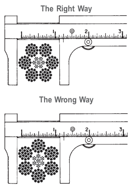
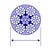
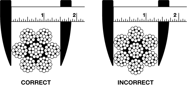
We are often called out to a job-site or facility to assist in determining the size of wire rope (and are happy to do so!). To measure yourself, the actual diameter of a wire rope is the diameter of a circumscribed circle that will enclose all the strands. It’s the largest cross-sectional measurement as shown here. You should make the measurement carefully with calipers, preferably digital. The illustrations above show the correct and incorrect methods of measuring wire ropes with even numbers of outer strands.
It should be mentioned that wire rope is normally made slightly larger than its catalog (or nominal) size. Wire rope allowable tolerances are +8% on rope sizes up to 1/8”, +7% on sizes between 1/8” and 3/16”, +6% on sizes between 3/16” and 5/16” and +5% on wire rope sizes over 5/16”. Ropes will also lengthen during use and the diameter will get slightly smaller over time so please keep that in mind while measuring. Additionally, wire rope running over sheaves will flatten the strands and alter the diameter over time.
It can therefore be tricky to determine the exact size and type of wire rope! It is best to find your manual, original documentation or Google it (just kidding!) We at Fulcrum lifting are a FULL SERVICE RIGGING SHOP and are happy to assist – so call your rep or bring in a sample and we can help in getting you the correct replacement.

To see which colors and types of rope are available for retail sale in each diameter, please visit the collections below. You can also filter rope by color or rope size using the side menu bar on any rope collection page.
Rope Size: Diameter and circumference are nominal. A new, unused rope in a relaxed state will measure larger; loading and use compacts ropes, sets splices, and lessens rope size. This is especially prevalent in rope sizes above 4" diameter. Published nominal sizes from 4-1/8" and larger represent stabilized or preloaded size.
Ravenox provides ropes for a variety of markets, from offshore working and lifting lines, tug and salvage, ship and barge mooring lines, mining tow lines, utility and RV winch lines to theatrical rigging lines and commercial fishing lines. Email Ravenox for a quote or for more information for ropes suitable for a variety of market solutions.

A distinction is made between the nominal rope diameter and the effective rope diameter. The nominal wire rope diameter is an agreed theoretical value for the diameter of the smallest circle circumscribing the outer strands.
The effective rope diameter, also called actual rope diameter, is the diameter of the smallest circle enclosing all outer strands, as measured on the rope itself. The tolerance range for the effective rope diameter is specified in related national and international standards. According to EN 12385-4 it is between -0{a889db705b9dbdba2a8d0dbcfc2b631547dc85af52ef75a70f044d2486ae0f02} and +5{a889db705b9dbdba2a8d0dbcfc2b631547dc85af52ef75a70f044d2486ae0f02} (for nominal rope diameters ≥ 8mm)
This means that the effective rope diameter upon delivery must neither be smaller nor bigger than 5{a889db705b9dbdba2a8d0dbcfc2b631547dc85af52ef75a70f044d2486ae0f02} than the nominal rope diameter. The tolerance range is often higher for smaller ropes like 3mm to 7mm nominal diameter. In the Oil and Gas industry, which is firmly based on US regulations, a tolerance range from -1{a889db705b9dbdba2a8d0dbcfc2b631547dc85af52ef75a70f044d2486ae0f02} to 4{a889db705b9dbdba2a8d0dbcfc2b631547dc85af52ef75a70f044d2486ae0f02} is applied. The effective rope diameter changes depending on the load applied. Therefore the effective rope diameter should in critical cases be measured on a rope that is loaded with 5{a889db705b9dbdba2a8d0dbcfc2b631547dc85af52ef75a70f044d2486ae0f02} of the calculated breaking strength. verope® produces standard tolerances of +2{a889db705b9dbdba2a8d0dbcfc2b631547dc85af52ef75a70f044d2486ae0f02} to +4{a889db705b9dbdba2a8d0dbcfc2b631547dc85af52ef75a70f044d2486ae0f02} and special tolerances upon request.
By the design of a wire rope, one understands the formation principle according to which the elements of the wire rope (the wires and the strands) are arranged relative to each other. The designation of a fiber core is FC, for an independent steel wire rope core it is IWRC. As an example all round strand ropes of the 6×19 Warrington design with a fiber core have the construction 6 x [1-6-(6-6)] – FC.
The fill factor of a rope is defined as the ratio of the metallic cross section of the rope (or a simplified calculation of the sum of the single wire cross sections) related to the nominal rope diameter. The fill factor specifies which amount of space the wires and strands take in the rope (figure 16).
The fill factors of the most common ropes are between 0,46 and 0,75. This means, that the amount of steel in the rope volume is about 46{a889db705b9dbdba2a8d0dbcfc2b631547dc85af52ef75a70f044d2486ae0f02} to 75{a889db705b9dbdba2a8d0dbcfc2b631547dc85af52ef75a70f044d2486ae0f02}. Wire ropes with a wire rope core have higher fill factors than ropes with a fiber core.
Usually fill factors of wire ropes with a fibre core (FC) decrease with an increasing number of outer strands. A rope of the design 6×25 Filler-FC has a fill factor of 0,50, a rope of the design 8×25 Filler-FC has only a fill factor of 0,445.
Usually fill factors of wire ropes with a wire rope core increase with an increasing number of outer strands. A rope of the design 6×25 Filler-IWRC has a fill factor of 0,58 and a rope of the design 8×25 Filler-IWRC has a fill factor of 0,587.
Two lay types are to be considered: Regular or ordinary lay and lang’s lay. In regular lay ropes, the lay direction of the wires in the strands is opposite to the lay direction of the strands in the rope. We distinguish between right hand ordinary lay RHOL (right hand strand, left hand rope, zS) (figure 17) and left hand ordinary lay LHOL (left hand strand, right hand rope, sZ) (figure 18). In lang’s lay ropes, the lay direction of the wires in the strands is equal to the strands in the rope. We distinguish between left hand lang’s lay LHLL (left hand strand, left hand rope, sS) (figure 19) and right hand lang’s lay RHLL (right hand strand, right hand rope, zZ) (figure 20).
In the stranding process the initially straight wires are forced into a helical or double-helical form. Therefore, the wires in a rope are always under tension, even in an unloaded rope. Such a rope must be sealed very tightly left and right of the joint before cutting the rope because otherwise the free ends of the wires will spring open. By using a “preforming tool”, the wires and strands can be heavily plastically deformed during the stranding, so are laying nearly without tension in the rope, the rope now is preformed. The ropemakers consider such ropes to be “dead”. Preformed ropes can be cut much easier, also secured by seizings of course, than nonpreformed ropes.
Usually wire ropes have either a fiber core (FC) or a steel/wire core. The steel/wire core can be a strand (WC) or a small rope, named as independent wire rope core (IWRC). The IWRC can be made in a separate operation or during the closing operation of the wire rope (PWRC). The wire core can also have a plastic coating (EPIWRC). Cores made of compacted strands have the additional designation (K). An independent wire core made of compacted strands is therefore called IWRC (K). A rope closed in a single operation and made out of compacted strands both in the core and the outer strands is called PWRC (K).
wire ropes and their free rope end rotate to a greater or lesser extent around its longitudinal axis under the influence of tension. Wire ropes having a core lay direction opposite to the lay direction of the outer strands and 3- or 4-strand regular lay wire ropes rotate considerably less than wire ropes with the same lay direction of the wire core and the outer strands and wire ropes with fiber cores. According to VDI 2358, a wire rope is semi rotation-resistant when: “the wire rope which turns around its longitudinal axis when subjected to unguided load and/or hardly transmits a torque to the attachment at the end in the event of guided rope ends.”
According to ISO 21669 and DIN EN 12385-3: “a rope is considered to be semi rotation resistant if it rotates at least once and at most four times around its axis at a length of 1000 x d under a load of 20 {a889db705b9dbdba2a8d0dbcfc2b631547dc85af52ef75a70f044d2486ae0f02} of the minimum breaking force. In terms of rotation angle, the defined limits are between 360° and 1440°.”
According to the regulation of VDI 2358, a wire rope is rotation-resistant, when: “the wire rope, which hardly turns around its longitudinal axis when subjected to unguided load and/or hardly transmits a torque to the attachment at the end in the event of guided rope ends.”
The wire rope lubricant has two major tasks: it should protect the rope from corrosion and minimize the friction between the rope elements themselves and between the rope and the sheave or the drum. A reduction of the friction reduces the actuating power and minimizes the wear of the rope, the sheaves and the drums. We differentiate between wax-based lubricants and oil-based lubricants. While wax-based lubricants offer a better handling of the ropes, the oil-based lubricants advantage is a better closing of the lubrication film due to the gravitational force of the oil. The quality of the wire rope lubricant has a great impact on the fatigue resistance of a wire rope (figure 22).
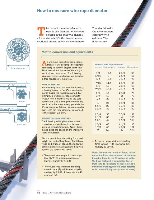
The actual diameter of a wire rope is the diameter of a circumscribed circle that will enclose all the strands. It’s the largest cross-sectional measurement as shown here. You should make the measurement carefully with calipers.
The rope diameter should be measured on receipt for conformity with the specification. British Standard (B.S. 302:1987, standard steel wire rope, Part 1. Clause 5.1) allow for a tolerance of - 1% to 4 % of the nominal rope diameter.
The generally accepted method of measuring rope diameter for compliance with the standard is to use a caliper with jaws broad enough to cover not less than two adjacent stands. The measurement must be taken on a straight portion of rope at two points at least 1 meter apart. At each point two diameters at right angles should be measured. The average of the four measurement is the actual diameter.
After the rope has made the first few cycles under low load, the rope diameter should be measured at several points. The average value of all the measurements at each point must be recorded and will form the basis of comparison for all future measurements.
The measurements of the rope diameter an essential part of all inspections and examinations. It ensures the maximum diameter reduction does not exceed the recommended figure. As stated in 5.2 British standard 6570 recommends that a wire rope should be discarded when the diameter of the rope is reduced to 90% of the nominal diameter.
A comparison of the measured data with the recorded previous values can detect an abnormal rate of reduction in diameter. Coupled with assessment of previous rope examination data, the probable date of rope renewal can be predicted.
If we examine the cross-section of a six-stand wire rope, we will find that measuring the thickness of the rope over the crowns (Fig-a) will produce a higher value than measuring it over the valleys (Fig-b). The actual diameter of the rope is defined as the diameter of the circumscribing circle.
When using a conventional caliper, wire rope with an even number of outer strands (four-, six, eight-, and multi strand) ropes must be measured from crown to crown. The advantage of a proper wire rope caliper with measuring plates is that even if the measurement is carried out "incorrectly", adjacent crowns are always included, so that the actual diameter is determined at any section. (Fig-c)
Measuring the diameter of wire rope with an uneven number of outer strands (three, five, seven, or nine-strand ropes) is more complicated: a crown on the one side of the wire rope always has a valley as a counterpart on the other side of the wire rope. A conventional caliper, therefore, has to be applied diagonally to the axis of the rope, so that at any time a crown adjacent to a valley is covered. Again a wire rope caliper with measuring plate is definitely to be preferred as it always includes strands crowns.
In all cases during periodic examinations where the measurements are to be recorded, the rope should be measured as already described. Where the roundness is being checked to detect potential faults, two diameters, one at right angles to the other can be taken and noted in the records. The entry into the records might read rope diameter : 20.4/20.5mm.
After a rope has been fitted to the appliance, its length cannot be measured again accurately, with out a great deal of trouble. The purpose of measuring the length of lay is to detect any increase in the rope length which may have been caused by corrosion, core deterioration or rope rotation (unlaying). With n new rope the wire and strands should be allowed to settle into their permanent position. Six or seven lifting cycles with a light to medium load are recommended before measuring error, the measurement should be made over four lays and the length divided by four lays and the length divided by four to find the average lay length.
On eight strand ropes the eight, sixteen, twenty-four and thirty-second strands must be marked. Using a straight length of the rope and with the rope under no load, first mark any strand on the crown with a piece of chalk; this strand now become"" crown zero"". Excluding this strands, count the next eight strands and mark the eight strand with chalk. Exclude the eight strand and repeat the procedures further two times. The measured length between the outer chalk marks is then divided by four to give the lay length.
As a rough check on the overall accuracy of the chalk marking, the length of lay for eight strand ropes is approximately between 6.25 and 6.5 x the diameter of the rope e.g. using a lay length of 6.5 x rope diameter, four lay length of a 32mm diameter rope will be 32mm x 6.5 x 4=832mm.
An alternate method of measuring the rope lay is to secure the free end of the roll of adding machine paper to the rope with adhesive tape. The paper is rolled out over the rope and simultaneously the wax pencil is drawn over the paper, providing a clear print of the outer wires of the rope. The finished print can be field for comparison with later measurements.
A third method is to wrap typing carbon papers round the rope under the roll of paper. By rubbing along the paper with a piece of cardboard, the carbon marking on the underside of the paper can be confined to the tops of the strand crowns.
Laid rope was always calibrated by circumference, whether you work in imperial or metric unit. The reason is very simple that any other method would give differing results depending on where you measure - just try this with a vernier caliper and turn the rope: the measured diameter will change as you turn it. You could use a gauge with holes, but keeping such gauge e.g. on board a ship would be inconvenient. It was easier to wind a thread say ten times around a rope and then measure its length, divided by ten it gives you the circumference.
When wire rope and then later braided fibre-rope came into use, measuring diameters became physically possible. However, well into the 20th century wire rope was sold by circumference.

Industrial wire ropes are designed for extreme resilience and strength. They can withstand thousands of pounds of pressure and be used on all types of applications. However, issues with the wire rope installation process can significantly decrease its longevity and even its capacity and durability.
When wire ropes are not used properly, it can create an unsafe environment. The rope can snap, even if the load it’s supporting is below its maximum load limit. In anoted by the IMCA (International Marine Contractors Association), a wire rope sling rope broke due to improper installation. A crew member was seriously injured after the sling disconnected and hit the worker.
Many of these common accidents are easily avoidable through correct wire rope installation. Here are five of the most common mistakes made and how to prevent them on your worksite.
Determining the diameter of the wire rope is an essential step of the installation process. Installers are required to double-check that the correct diameter rope is being used, as this impacts the rope’s breaking strength and load limit.
Wire ropes are measured with a parallel-jawed caliper (also called a machinist’s caliper). This is placed over the wire rope to measure the diameter – but if the rope is inserted at the wrong angle, you will get an inaccurate result.
The strands of a wire rope must be flush against the measuring portion of the caliper. If a raised strand is at the top, the measurement will have a smaller dimension, which could affect breaking strength calculations.
Wire ropes are reeled onto these spools for easy handling and shipments, as it prevents the rope from getting tangled or crushed. But unreeling the wire rope incorrectly can cause severe damage, such as snagged wires, twists, kinks, or unraveled strands.
A common mistake that is often made is to unreel the wire rope by laying the spool vertically on its axis. The wire rope has to be yanked off of the spool, which increases the likelihood of it getting kinked or twisted. The wire rope should also not touch the ground as it is unreeled, as this could damage the wires as well.
Instead, the reeled wire rope should be placed on a shaft that allows the spool to turn 360°. It also should require two people, one to slowly pull the rope off of the spool in a straight line and another to regulate the speed by controlling the turn rate.
Occasionally ais added during wire rope installation to create a load-bearing eye or to connect two cables together. These small but mighty pieces only diminish a wire rope’s strength by around 10%, if they are added correctly.
These little issues can cause the wire rope to slip out of the clip. It is very important to follow the directions and use the right number of clips with the correct spacing in-between, depending on the rope’s diameter and approximate load weight.
Sometimes a damaged wire rope can be repaired through a method called seizing. First, the rope is cut at a straight angle, then a wire is tightly wound around this end to prevent the strands from unraveling.
Two methods can be used to securely seize a wire rope. First, it can be placed at a right angle between the starting and ending point of the seizing. The wire is then wrapped around this angled piece to hold it in place, and the ends are twisted together to secure it. Another option is to wrap the seizing wire around and twist the two end pieces together, creating a tourniquet type of attachment.
The type of end preparations recommended depends on several factors. This includes the diameter of the rope and the number of wires and strands. In some cases, double seizing and fuse welding is required for additional securement. Failing to follow these instructions could result in the core or strands of the wire rope to slip and unravel.
Although wire ropes are usually damaged due to improper use, they can get ruined during storage as well. Failing to follow through with routine maintenance and storage recommendations could cause the wire rope to rust, unravel, or kink. Further, keeping your wire rope on the ground, in wet areas, or directly in hot sunlight can cause it to break down faster.
the right way can improve their long-term performance and use. This includes following all instructions during wire rope installation, as well as storage and upkeep. Wire ropes should be cleaned before going into storage and may need lubricant from time to time to protect the wires from drying out.
Wire ropes are intended to be a strong, reliable piece of industrial hardware. There is no reason to compromise its durability due to simple installation mistakes. By avoiding these common mishaps, you can ensure a far safer work environment and also extend the use of your wire ropes.
Another tip is to start by purchasing top-quality hardware from a trusted wire rope supplier. Elite Sales is proud to carry a vast selection of wire rope sizes, styles, and finishes that are made to fit many applications.
Steel ropes and hot wire are in long lengths and at high speeds correctly cut to length. In both cases, contact measurement devices are very susceptible to wear. With sufficient material guidance, μSPEED systems reliably and permanently measure all materials and speeds.
Maintain a record for each rope that includes the date of inspection, type of inspection, the name of the person who performed the inspection, and inspection results.
Use the "rag-and-visual" method to check for external damage. Grab the rope lightly and with a rag or cotton cloth, move the rag slowly along the wire. Broken wires will often "porcupine" (stick out) and these broken wires will snag on the rag. If the cloth catches, stop and visually assess the rope. It is also important to visually inspect the wire (without a rag). Some wire breaks will not porcupine.
Measure the rope diameter. Compare the rope diameter measurements with the original diameter. If the measurements are different, this change indicates external and/or internal rope damage.
Visually check for abrasions, corrosion, pitting, and lubrication inside the rope. Insert a marlin spike beneath two strands and rotate to lift strands and open rope.
Assess the condition of the rope at the section showing the most wear. Discard a wire rope if you find any of the following conditions:In running ropes (wound on drums or passed over sheaves), 6 or more broken wires in one rope lay length; 3 or more broken wires in one strand in one rope lay. (One rope lay is the distance necessary to complete one turn of the strand around the diameter of the rope.)
Corrosion from lack of lubrication and exposure to heat or moisture (e.g., wire rope shows signs of pitting). A fibre core rope will dry out and break at temperatures above 120°C (250°F).
Kinks from the improper installation of new rope, the sudden release of a load or knots made to shorten a rope. A kink cannot be removed without creating a weak section. Discarding kinked rope is best.

The 6 x 19 classification of wire ropes includes standard 6 strand, round strand ropes with 16 through 26 wires per strand. The 6 x 36 classification of wire ropes includes standard 6 strand, round strand ropes with 27 through 49 wires per strand. Although their operating characteristics vary, all have the same weight per foot and the same nominal strength, size for size.
While the 6 x 19 ropes give primary emphasis to abrasion resistance in varying degrees, the 6 x 36 ropes are important for their fatigue resistance. This fatigue resistance is made possible by the greater number of small wires per strand.
Although there are exceptions for special applications, the constructions in 6 x 36 classification are primarily designed to be the most efficient for each rope diameter. As the rope size increases, for instance, a large number of wires can be used to achieve required fatigue resistance, and still those wires will be large enough to offer adequate resistance to abrasion.
In this construction, each strand has nine outer wires over nine smaller inner wires over one large center wire. A comparison of cross-sections shows that these outside wires are larger than those of the 6 x 25FW or 6 x 26WS. Therefore, its resistance to abrasion is increased, but its fatigue resistance is decreased. This is a good rope to withstand abrasion or crushing on the drum.
To most wire rope users, 6 x 19 means 6 x 25 filler wire. It is the most common rope in the 6 x 19 classification. This rope has a good balance between both abrasion resistance and fatigue resistance in relation to other ropes.
This construction has better resistance to abrasion than a 6 x 25FW. It also features a compact construction with solid support for the wires; hence, it has a high resistance to crushing. Its number and relative size of the inner wires add to the stability of the strand and gives it a fatigue resistance comparable to a 6 x 25FW.
A standard 6 x 26WS construction provides the best rope for a wide range of applications. In general, we recommend the use of a 6 x 26WS in any application where a 6 x 25FW is used.
In most rope sizes, only one 6 x 36 classification rope is made. These constructions were selected to provide fatigue resistance without having wires that are too small.
The greater number of wires in the 6 x 36 classification makes these ropes more susceptible to crushing. This can be minimized, however, by specifying an Independent Wire Rope Core (IWRC) and by using well-designed sheaves, grooved drums and proper operating techniques.
Rotation-resistant ropes can frequently provide the best and most economical service in specific applications when you choose, handle and use them properly.
Contra-helically laid, rotation-resistant ropes are different from standard ropes because they"re designed to reduce rope torque. Modes of failure and wear for rotation-resistant ropes can differ from those for standard rope constructions. The very nature of these ropes requires special handling, selection and usage not encountered with standard constructions. They are susceptible to kinking, crushing and unbalancing in the form of "core pops" and "birdcages" Use extreme care to avoid operational practices that can possibly lead to these conditions.
Rotation-resistant ropes should not be used with swivels that allow rope rotation -- or in single part lifts where the load can rotate. Rotation will cause a reduction in strength, unequal loading in the rope and possible rope unbalance. If any significant change in diameter is found in a short length of a rotation-resistant rope, the rope needs to be replaced.
These ropes should be replaced when you see two randomly distributed crown wire breaks in six rope diameters -- or four randomly distributed crown wire breaks in 30 rope diameters.
Because rotation-resistant ropes are special, there are separate design, maintenance, inspection and removal criteria established for them by applicable industry regulations and standards.
In an application where a single-part hoist rope is used to lift a free load -- or where rotation-resistant properties are essential for rope performance -- the 19 x 7 can be used. Its rotation-resistant characteristic is achieved by laying six strands around a core strand in one direction, then laying 12 strands around the first operation in the opposite direction. Thus, when the rope is in tension, opposing rotational forces are created between the inner and outer layers.
In addition, frequent and regular inspection for broken wires is critical when using this rope. Due to its design, the 19 x 7 construction has a relatively low reserve strength. This can result in short service life between the point in time when the broken wire removal criteria are met and when actual rope failure occurs.
In a multi-part wire rope system where the blocks have a tendency to twist -- or for a single-part hoist line that doesn"t require the degree of rotation-resistant properties found in a 19 x 7 rope -- the 8 x 25 Resistwist rope has found successful application. The rotation-resistant characteristic is achieved by laying the eight outer strands around an independent wire rope core so these strands are in the opposite direction to the lay of the core. Thus, when the rope is in tension, opposing rotational forces are created between the core and the outer strands.
Though not as rotation-resistant, the 8 x 25 Rotation Resistant rope is more stable than a 19 x 7 rope. It also has increased resistance to bending fatigue and crushing. This is achieved through the use of eight-strand construction with an independent wire rope core.
Like any application where an installation"s rope type is changed, the 8 x 25 Rotation Resistant rope should be substituted only after carefully comparing specifications and strength requirements.

Construction The size and number of wires in each strand, as well as the size and number of strands in the rope greatly affect the characteristics of the rope. In general, a large number of small-size wires and strands produce a flexible rope with good resistance to bending fatigue. The rope construction is also important for tensile load (static, live or shock) abrasive wear, crushing, corrosion and rotation. The number of strands and wires will influence the flexibility, fatigue and wear resistance of any given wire rope. Rope selection is often a compromise. Generally the more load bearing wires in the rope the greater the flexibility, however the smaller the wires the less abrasion resistance. For example, the same nominal diameter 7 x 7 wire would be less flexible than a 7 x 19 wire, hence a large number of small size wire and strands produce a flexible rope with good resistance to bending fatigue wear. The construction of wire rope is defined by the number of outer strands (first number), and the number of wires within that strand (second number) and then by the arrangement of the wires in each strand (shown in brackets). The wires in each strand can be arranged in several ways, for example a 6 x 19 construction the 19 wires in each strand are laid 9 around 9 around 1 centre wire.
Endurance Dyform 6 20-22// Usha Martin Crane Wire Rope 23-25// Wire Rope Slings Overview 26 // Tri-flex Wire Rope Slings 27 // Wire Rope Terminations 27 //
Core The core of a steel wire rope serves as a foundation for the strands, providing stability by keeping them in place throughout the life of the rope. Wire ropes can be supplied with either a fibre or wire core. Grade Wire rope can be manufactured in different steel grades, which directly affects the Minimum Breaking Force, (MBF). The higher the grade the higher the MBF. Common wire grades include: 1570, 1770, 1960 and 2070 Finish Wire Ropes can be supplied as Black (self-colour), Galvanised or Stainless Steel. Wire rope is lubricated at the time of manufacture, to help reduce friction between wires and strands, and the friction between the rope and drum or sheave. In addition, the lubrication retards corrosion and inhibits possible rotting of the fibre core.
RHOL Right Hand Ordinary Lay LHOL Left Hand Ordinary Lay RHLL Right Hand Lang’s Lay LHLL Left Hand Lang’s Lay Pref Preformed Post Postformed WRC Wire Rope Core WSC Wire Strand Core FC Fibre Core FW Filler Wire Strand Construction D or d Diameter (in millimetres)
Rotating or Non-Rotating Rotation resistant wire ropes are manufactured to resist rotation under load and are suitable for crane use and where long lengths are required.
Clamping Wire Rope To ensure complete safety, it is imperative that wire ropes are clamped correctly. The diagrams below are a guide only. Please refer to the relevant Australian Standards AS 2076 for further information.
Correct Spooling of Steel Wire Rope on Drum It is imperative to correctly spool wire rope onto a drum. Improper spooling induces torque within the rope, which in turn reduces the life of the rope.
tension to avoid any slack on inner layers that can be crushed or nicked against the groove walls by outer layers. In general, the tighter the line, the better the spooling, but the rope should be tensioned with at least 2% of the breaking load or 10% of the working load.
Lubricating Steel Wire Ropes All steel wire ropes supplied by Robertsons are lubricated at the time of manufacture, however, periodic lubrication with good quality acid free and moisture free lubricant during use is required to ensure best performance. The following are accepted ways to lubricate wire ropes during use.
Steel Wire Rope Cutting Procedure Hand cutters for cutting ropes up to 8mm in diameter are sufficient. Mechanical or hydraulic cutters will be required for wire ropes with larger diameters.
Careless cutting can result in the balance of tension in the rope being destroyed. In every case, each side of the cut must be correctly seized to prevent strand
C: Both ends of the seizing wire are then pulled tight and twisted together for a length of one rope diameter. The twisted connection is then hammered into a strand valley.
Typical Steel Wire Rope Failures Steel wire rope is tough and durable, however eventually it will reach the end of its safe service life. Below are some examples of typical damage and deterioration. Steel wire ropes should be inspected every 12 months.
Storing Steel Wire Ropes Ensure steel wire rope is stored in a weather-proof storage space. If wire rope is to be kept unused for a considerable amount of time, it must be protected from the elements. The ideal storage area is a dry, well-ventilated building or shed. Avoid closed, unheated, tightly sealed buildings or enclosures because condensation will form when warm, moist outside (ambient) air envelopes the colder rope. Although wire rope is protected by a lubricant, this is not totally effective since condensation can still occur within the small sections between strands and wires, thereby causing corrosion problems. Ensure the reels are kept up off the ground, or are placed on a concrete floor. • Reels should be mounted on jacks or placed on a swift (with a brake arrangement) and care taken to see that the reel rotates as the rope unwinds • Ensure clearance for free rotation of the reel when the rope end is pulled and maintain continuous tension during haul off Correct Handling of Steel Wire Ropes Incorrect handling of steel wire ropes can cause kinking or loops Ropes should be stored in a clean dry place under cover. Reels or coils should be kept off the ground and supported by timber. They should also be examined periodically and rope dressing renewed as required. 1) Unreeling and Uncoiling Reels should be mounted on jacks and care taken to see that the reel rotates as the rope unwinds. Timber should be applied as a lever to one of the flanges to act as a brake, keeping the rope tight and preventing the reel from over- running. When the ropes are supplied in coils a turntalbe or swift should be employed and the free end pulled out with event tension as the swift, or turnatable revolve. Over-winding should be avoided at all times to obviate kinking. Coils may also be unwound by securing the free outside end of the rope and then rolling the coil along the ground; care being taken at all times to ensure that the coil is held firmly together, avoiding tight coils or kinks. Ropes should be stored in a clean dry place under cover. Reels or coils should be kept off the ground and supported by timber. They should also be examined periodically and rope dressing r newed as required. 1) Unreeling and Uncoiling Reels should be mounted on jacks and care taken to see that th reel ro ates as the rope unwinds. Timber should be applied as a lever t one of the flanges to act as a brake, keeping the rope tight and pr ve ting the reel from over- run ing. When the ropes are supplied in coils a turntalbe or swift should b employed and the fre end pulled out with vent tension as the swift, or turnatable revolve. Over-winding should be avoided t all times to obviate kinking. Coils may also be unwound by securing the free outside end of the rope and then rolling the coi along the ground; care being taken t all times to ensure that the coil is held firmly together, avoiding tight coils or kinks. Ropes should be stored in a clean ry lace under cove . R ls or coils shoul be k pt off the ground and supported by timber. They should also be examined periodically and rope dressing renewed as required. 1) Unreeling and Unc iling Re s should be mounted on jacks and c re taken to se that the reel r tates as the rope u winds. Timbe should be appl ed as a lever to one of the flanges to act as a brake, keeping the rope tight and preventing the reel from over- running. When the rope are supplied in coils a turntalbe or swift employed and the free end pulled out w th event tension as the swift, or tur atabl rev lve. Ov r-winding shoul be av ided at all t mes to obviate kinking. Coils may also be unwound by sec ing the fr e out id end of th rope and the rolling the c il along the ground; care being taken at all times to ensure that the coil is held firmly together, avoiding tight coils or kinks. Ropes should be stored in a clean dry place under cover. Reels or coils should be kept off the ground and supported by timber. They should also be examined periodically and rope dressing renewed a required. 1) Unreeling and Uncoiling Reels should be mounted on jacks and care taken to see that the reel rotates as the rope unwinds. Timber should be applied as a lever to one of the flanges to act as a brake, keeping the rope tight and preventing the reel from over- running. When the ropes are supplied in coils a turntalbe or swift should be employed and the free end pulled out with event tension as the swift, or turnatable revolve. Over-winding should be avoided at all times to obviate kinking. Coils may also be unwound by securing the free outside end of the rope and then rolling the coil along the ground; care being taken at all times to ensure that the coil is held firmly together, avoiding tight coils or kinks. Ropes should be stored in a clean dry place under cove . R els or coils should be k pt off the ground and supported by timber. They should also be xamined p riodically and rope dressing renewed as required. 1) Unreeling and U c iling Reels should be mounted on jacks and care taken to see that the reel tates as the rope u winds. Timb r should be appl ed as a lev r to ne of the flanges to act as a brake, keeping the rope tight and prev nti g the reel from over- running. When the rope are supplied in coils a turntalbe or swift empl y d and the free end pull d out with event tensi n as the swift, or t r at ble rev lve. Ov r-winding sh uld be avoided at all times to bviate kinki g. Coils may also be unwound by securing the free out id nd of the rop and then rollin the coil a ong the ground; care being taken at ll times to ensure that the coil is held firmly together, avoiding tight coils or kinks. forming in the steel wire rope, causing permanent damage. Below is a summary of the correct way to handle steel wire rope:
Although the steel wire rope is lubricated at the time of manufacture, a suitable lubricant should be applied every three months. The reels containing the steel wire ropes should also be rotated 90 degrees every three months.
11. Handling and Care of Wire Ropes 1. Handling and Care of Wire Ropes 11. Handling and Care of Wire Ropes 11. Handling and Care of Wire Ropes 1 . Handling and Care of Wire Rop s
2) Seizings It is important that before cutting ropes are properly seized with annealed mild steel wire or strand to avoid slack wires and possible rope distortion. 2) Se zings It s important that before cutting ropes are properly s ized with annealed mild steel wire or strand to avoid slack wires and possible rope distortion. 2) Seizings It is important that bef re cutting ropes are properly seized with annealed mild steel wire or strand to avoid slack wires and possible rope distortion. 2) Seizings It is important that before cutting ropes are properly seized with annealed mild steel wire or strand to avoid slack wires and possible rope distortion. 2) Seiz ngs It is important that before cutting ropes are properly seized with annealed mild steel wire or strand to avoid slack wires and possible rope distortion.
Wire Rope Terminations Hand spliced or machine swaged slings, with your choice of terminations, can be manufactured and tested (if required) on our premises at short notice. All slings and assemblies are permanently marked with safe working loads, based on a 5:1 factor of safety. Machine Swaging Aluminium Ferrules Sizes 2mm – 52mm. Copper Ferrules Sizes 2mm – 10mm Steel Ferrules Sizes 9mm – 75mm Swage Sockets Sizes 3mm – 52mm Hand Splicing from 2mm – 75mm dia
Galvanised Wire RHOL 63 41.8 Galvanised Wire RHOL 90 60.2 Galvanised Wire RHOL 107 70.7 Galvanised Wire RHOL 124 82 Galvanised Wire RHOL 161 107 Galvanised Wire RHOL 204 135 Galvanised Wire RHOL 252 167 Galvanised Wire RHOL 304 202 Galvanised Wire RHOL 363 241 Galvanised Wire RHOL 426 283 Galvanised Wire RHOL 493 328 Galvanised Wire RHOL 644 428 Galvanised Wire RHOL 816 542 Galvanised Wire RHOL 911 604 Galvanised Wire RHOL 1009 669 Galvanised Wire RHOL 1220 810 Galvanised Wire RHOL 1700 1110
Galvanised Wire RHOL 18.9 10.4 Galvanised Wire RHOL 27.2 14.3 Galvanised Wire RHOL 37.2 20.2 Galvanised Wire RHOL 47.5 25.66 Galvanised Wire RHOL 59.3 32 Galvanised Wire RHOL 73 39.4
POWERFORM® 8/8P • A high strength eight strand rope with plastic impregnated core ideal for situations where longer service life is required • High fatigue life resulting from the unique compaction process • Maximum resistance to crushing. Recommended for multi-layer spooling operations
• A sample of rope from each production batch is tested to destruction • Greater surface contact area resulting from the eight strand construction and compacted finish give longer rope life and reduced sheave wear • Optional plastic impregnation of the steel core. (P) signifies full plastic impregnation of the steel core.
POWERFORM® 35/35P • Superior strength and resistance to rotation • Suitable for use on single part and multi-part hoist reeving systems • High fatigue life due to unique compaction process • A sample of rope from each production batch is tested to destruction
52 2256.0 230.0 *Mass per unit length of POWERFORM 35P increases by approx. 3%. Note: • POWERFORM 35P is available on special request and prior confirmation. • Rope sizes and Breaking Force not shown in the standard table, may be available on request and prior confirmation.
Note: • POWERFORM 8P is available for rope diameter 16mm and above on special request and prior confirmation. • Rope sizes and Breaking Force not shown in the standard table, may be available on request and prior confirmation.
POWERFORM® 6/6P • A high strength rugged six strand rope ideal for situations where longer service life is required • Can be substituted for any six strand construction to improve service life • High fatigue life due to unique compaction process • A sample of rope from each production batch is tested to destruction
Typical Steel Wire Rope Sling Description Hand spliced or machine swaged slings, with your choice of terminations, can be manufactured and tested (if required) on our premises at short notice. All slings and assemblies are permanently marked with safe working loads, based on a 5:1 factor of safety.
*Mass per unit length of POWERFORM 6P increases by approx. 3%. Note: • POWERFORM 6P is available only for 16mm and above on special request and prior confirmation. • Rope sizes and Breaking Force not shown in the standard table, may be available on request and prior confirmation.


 8613371530291