
wire rope drive mechanism factory

This invention relates generally to the field of mechanical systems for providing reciprocating, linear motion for a movable structure or work piece relative to a fixed structure or work piece. More particularly, the invention relates to a drive mechanism providing reciprocating, linear motion from rotational motion of a motor, using a novel cable or wire rope drive mechanism. The invention is susceptible to many possible uses and installations, examples being drive systems for use in automated instruments for processing biological samples, and stacking systems for stacking cards or card-like bodies in a tray, which happen to be of particular applications presently employed by the present inventors. However, other possible uses of the invention in different types of machines and systems will be apparent to persons skilled in the art from the following detailed description, and thus the invention relates, primarily, to reciprocating drive mechanisms for a moveable work piece. [0002]
Drive mechanisms for providing reciprocating, linear movement of a moveable work piece relative to a stationary work piece or structure are known. An example is described in the patent of Clifford W. Karl et al., U.S. Pat. No. 5,674,454, assigned to the assignee of the present invention. Generally, the "454 patent describes a stacking system for stacking flat, thin, card-like objects in a magazine. The stacking system has a moveable push plate that is used to stack the objects in the magazine. In FIG. 7 of this patent, a motor has a pinion gear with teeth which engage complementary teeth of a push rack that is coupled to the push plate. The rotation of the motor causes the push rack to move back and forth in a linear fashion, causing a push plate to move back and forth relative to the magazine and thereby providing a mechanism for stacking the objects in the magazine. [0004]
Other drive systems known in the art include Levine et al., U.S. Pat. No. 5,854,075, which describes a drive belt system for moving a carriage assembly relative to a magazine containing a plurality of slides. Other patents describing belt-type drive systems include Seto et al., U.S. Pat. No. 5,660,793; and Shindo et al., U.S. Pat. No. 5,470,533. Porte et al., U.S. Pat. No. 5,073,342, describes a simple reciprocating piston-acruated transfer mechanism. Forsstrom, U.S. Pat. No. 3,221,781 contemplates a similar type of arrangement for moving sample carriers about an analytical instrument. Other reciprocating belt and paddle-based drive mechanisms are described in the patent of William E. Seaton et al., U.S. Pat. No. 5,736,102, which is also assigned to the assignee of the present invention. [0005]
While the drive mechanism of the type described in the above-cited are work satisfactorily for many applications, the present invention is considered to be an improvement over these and other types of systems. The present drive mechanism and method is believed to provide improved reliability in extended use, and decrease the amount of maintenance for the user. Further, the design is quiet in operation. The design is easy to assemble and less costly to manufacture than systems based on the design of the above-cited Karl et al. patent. [0006] SUMMARY OF THE INVENTION
In a first aspect, a drive mechanism for providing reciprocating, liner motion for a movable work piece relative to a stationary work piece is provided. The drive system includes a motor rotating a drum in forward and reverse directions about a first fixed axis. The motor is fixedly mounted with respect to the stationary work piece, such as to a housing or other structure. The system further includes an elongate, substantially non-flexible cable having first and second ends, which are fixed with respect to the stationary work piece. The cable, which in a preferred embodiment takes the form of a wire rope, further comprises an intermediate portion extending between said first and second ends, with the intermediate portion being wound around the drum. [0007]
The drive mechanism of the invention can be installed in any type of system that may benefit from quiet, reliable operation of a reciprocating linear drive mechanism. Preferred embodiments would be in automated biological sample testing instruments, and in stacking systems for flat, thin card-like objects. However, the invention is not limited to such systems. [0010]
In another aspect of the invention, a method is provided for moving a moveable work piece relative to a stationary work piece using an elongate, substantially non-flexible wire rope or cable, the cable having a first end and a second end and an intermediate portion between the first and second ends. The method includes the step of attaching the first and second ends of said cable to a structure fixed with respect to the stationary work piece. The method includes the step of winding the intermediate portion of the cable about a drum coupled to a motor, with the motor fixed with respect to the stationary work piece. The intermediate portion of the cable is further wound around the first and second bearings, with the first and second bearings mounted to the moveable work piece such that the first bearing is positioned between the first end of the cable and the drum and the second bearing is positioned between the second end of the cable and the drum. The method includes the step of rotating the drum, whereby the step of rotating causes the first and second bearings to move relative to the drum and thereby move the moveable work piece relative to the stationary work piece.[0011]

Rope drive is a form ofbelt drive, which is used for mechanical power transmission. Rope drives use multiple circular section ropes instead of single flats or V-belts. The rope drives are widely used where a large amount of power is to be transmitted, from one pulley to another, over a considerable distance.
The fibre ropes operate successfully when the pulleys are approximately 60 meters apart, while wire ropes are used when the pulleys are separated by 150 meters.
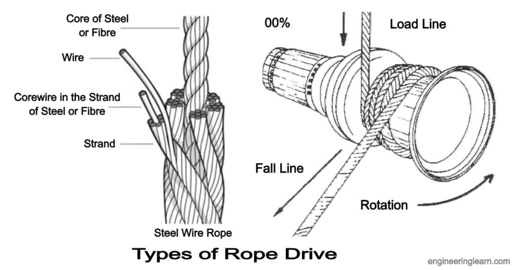
Wire rope is several strands of metal wire twisted into a helix forming a composite rope, in a pattern known as laid rope. Larger diameter wire rope consists of multiple strands of such laid rope in a pattern known as cable laid.
In the lifting and rigging industries, wire rope is attached to a crane or hoist and fitted with swivels, shackles or hooks to attach to a load and move it in a controlled matter. It can also be used to lift and lower elevators, or as a means of support for suspension bridges or towers.
Wire rope is a preferred lifting device for many reasons. Its unique design consists of multiple steel wires that form individual strands laid in a helical pattern around a core. This structure provides strength, flexibility, and the ability to handle bending stresses.
In stricter senses, the term wire rope refers to a diameter larger than 3/8 inch (9.52 mm), with smaller gauges designated cable or cords. Initially wrought iron wires were used, but today steel is the main material used for wire ropes.
Wire ropes are made from cold-drawn wires to increase strength and durability. It may be noted that as its size decreases the strength of the wire rope increases. The various materials used for wire ropes in order of increasing strength are iron, cast steel, extra-strong cast steel, steel, and alloy steel.
Wire ropes were developed starting with mining hoist applications in the 1830s. Wire ropes are used dynamically for lifting and hoisting in cranes and elevators, and for transmission of mechanical power.
It is also used to transmit force in mechanisms, such as a Bowden cable or the control surfaces of an airplane connected to levers and pedals in the cockpit.
A wire rope clip, sometimes called a u-bolt clamp or u-bolt clip is used to clamp the loose end of a length of wire rope, once it has been looped back to form an eye. These fittings consist of a u-bolt and has a saddle secured by two nuts.
The advantages of a wire rope are that they are more resistant to wear, have better crushing resistance, and high strength compared to a round strand wire rope of equal diameter and classification. However, a swaged wire rope may have less bending fatigue resistance.
Wire ropes are made from various grades of the steel wire with tensile strength ranging from 1200 to 2400 MPa. The wires are first given special heat treatment and then cold drawn for high strength and durability of the rope. Steel wire ropes are manufactured by specialized machines.
First, strands such as 7, 19, or 37 of the wire are routed into a strand, and then a number of strands, usually 6 or 8, are rotated about the core or center to form the rope. The core may be made of hemp, jute, asbestos, or soft steel wire. The core must be continuously saturated with lubricant for the long life of the core as well as the entire rope.
Asbestos or soft wire cores are used when the ropes are subjected to radiant heat such as cranes working near furnaces. However, a wire core reduces the flexibility of the rope, and such ropes are used only where they are subjected to high compressions. Such as in the case of the wounding of multiple layers on a rope drum.
Cross or Regular Laying Ropes: In these types of ropes, the direction of twisting of wires in the strides is opposite to the direction of the twist of the stand. These types of ropes are the most popular.
Parallel or lang lay ropes: In these types of ropes, the direction of rotation of the strands in the strands is similar to the strands in the rope. These ropes have a better bearing surface but are easily split and twisted when loaded. These ropes are more flexible and the wearer is more effective. Since such ropes have a tendency to rotate, they are used in lifts and waved by guide methods and also as rope ropes.
The direction of the laying of ropes can be right-handed or left-handed, depending on whether the strands form a right-handed or left-handed helix. But right-handed ropes are most commonly used.
Fibre ropes are made from fibres of varying length depending on their source. these are twisted up into yarns, and the twist given binds the fibres firmly together so that they hold by friction when the yarn is subjected to strain. The yarns are then laid up to form rope.
Ropes for transmission power are usually made of fibrous materials such as cannabis, manila, and cotton. Since hemp and manila fibres are rough, the ropes made of these fibres are not very flexible and have poor mechanical properties. The hemp rope has less strength than the Manila ropes.
When the hemp and manila ropes are bent over the sheave. The fibres cause some sliding, causing the rope to rub internally. To reduce this defect, rope fibres are lubricated with a tar, elongated, or graphite. Lubrication also makes the rope moisture-proof. Hemp ropes are suitable only for hand-operated hoisting machinery and for tackling rope tack, hooks, etc.
The cotton cord is very soft and smooth. Lubrication of cotton ropes is not necessary. But if it is done, it reduces the external wear between the rope and its edge grooves. It may be noted that Manila ropes are more durable and stronger than cotton ropes. Cotton ropes are more expensive than Manila ropes.
Manila and cotton ropes typically have a diameter of 38 mm to 50 mm. The size of the rope is usually specified by its circumference or ‘circumference’.
The ultimate tensile braking load of fibre ropes varies greatly. For Manila ropes, the average value of ultimate tensile braking load can be taken as 500 D 2 kN and for cotton ropes, it can be taken as 350 D 2 kN, where D is the diameter of the rope in mm.
Power transmission over long distances is the main application of rope drive. Rope drives are used to drive systems that are more than 8 meters in distance using a distance power transmission system. Metal ropes are used for distances beyond sixty meters. It is commonly seen in elevators and cranes.
Rope drive is a form of belt drive, which is used for mechanical power transmission. Rope drives use multiple circular section ropes instead of single flats or V-belts. The rope drives are widely used where a large amount of power is to be transmitted, from one pulley to another, over a considerable distance.
Wire rope is several strands of metal wire twisted into a helix forming a composite rope, in a pattern known as laid rope. Larger diameter wire rope consists of multiple strands of such laid rope in a pattern known as cable laid.
A wire rope clip sometimes called a u-bolt clamp or u-bolt clip is used to clamp the loose end of a length of wire rope, once it has been looped back to form an eye. These fittings consist of a u-bolt and have a saddle secured by two nuts.
The term cable is often used interchangeably with wire rope. However, in general, wire rope refers to diameters larger than 3/8 inch. Sizes smaller than this are designated as cable or cords. Two or more wires concentrically laid around a center wire is called a strand.
Available in various constructions, sizes and finishes, wire rope is a versatile material that can be used to (among other things) lift, hoist, separate, position, secure, remove, repair, readjust, support and brace items in a safe and effective manner. Wire rope was initially designed to assist in the mining industry.
Dyneema is the world’s strongest fiber-producing ropes that are 15 times stronger than steel wire ropes of the same weight and has become one the most trusted fiber ropes over generic HMPE ropes and steel cable wire ropes for all rigging, maritime, mooring, and towing rope applications.
Overall, wire rope is stronger than chain. The multi-strands of continuous wires give wire rope its strength, whereas a chain is joined together with links. These joins are the weakest part of a chain and can break under heavy loads.
Wire rope is a preferred lifting device for many reasons. Its unique design consists of multiple steel wires that form individual strands laid in a helical pattern around a core. This structure provides strength, flexibility, and the ability to handle bending stresses.
The various materials used for wire ropes are iron, cast steel, extra strong cast steel, steel, and alloy steel, in order of increasing strength. For some purposes, wire rope can also be made from copper, bronze, aluminum alloys, and stainless steel.
In general, the higher wire count of a 7×19 typically makes it a better choice for winches, garage doors, and other applications that require tighter and more frequent turns, while the rigidity of a 7×7 makes it a good choice for automotive and aircraft controls.
Braided rope is stronger and is nicer on the hands than twisted rope, but it’s a pain to splice yourself. This means if you’re using a windlass and chain, and you are doing your own splicing, you’ll probably need to use twisted rope.
6 x 19S (Seale) -This is a good rope to withstand abrasion or crushing on the drum but its fatigue resistance is decreased. 6 x 25FW (Filler Wire) – To most wire rope users, 6 x 19 means 6 x 25 filler wire. It is a common rope in the 6 x 19 classification.
A wire rope is stronger because the material that makes it is continuous, i.e. without joins. In a chain, individual links must be closed by joining their ends, and that reduces the tension it can handle.
Compared to chain, steel wire ropes have a higher strength-to-weight ratio, making them easier to install and lighter on the floating structure. Steel wire ropes are most commonly constructed of many thin steel wires wound into strands, which are then wound around a central core into the final wire rope.
You should generally use equipment with a working load limit that is rated for weight at least five times higher – or 250,000 lbs. in this case. This recommendation is all thanks to the wire rope safety factor.
A rope that has more strands exhibits greater flexibility than one with fewer strands. Crush resistance: Although wire rope with a fiber core offers the most flexibility, it also demonstrates less resistance to crushing. If crushing is not a concern but flexibility is, fiber core wire rope is ideal.
The helix or spiral of the wires and strands in a rope is called the lay. Regular lay denotes rope in which the wires are twisted in one direction, and the strands in the opposite direction to form the rope. … These ropes are more likely to twist, kink and crush than regular lay ropes.

The first multiple rope drive was a 9-rope drive of 200 bhp produced by Combe Barbourmanila hemp.vee pulley, as part of a Van Doorne or Variomatic transmission.textile machinery and differential speed gearing was often needed as part of the spinning process, where one shaft could be smoothly adjusted to run slightly faster or slower than another.
Rope drives were most widely used for power-transmission in mills and factories, where a single mill engine would have a large rope drive to each floor, where lineshafts across each floor distribute power to the individual machines. These multiple rope drives replaced the earlier technique of a vertical wrought iron shaft with bevel gears at each floor. They remained in use for as long as mills were driven by central steam engines, rather than individual electric motors.Droylesden split the output of one motor between two floors with two new rope drives.gas engines running on producer gas. A Yorkshire mill converted to use a 1,000 hp Allen diesel engine in 1938, and retained the rope drives.
Shaft drives had often used gearing from the engines to increase their speed, and thus their power transmission. This was avoided for rope drives, as the rope"s maximum useful speed could be achieved from the engine"s flywheel and flexibility of the ropes led to backlash in the gearing.
US practice sometimes used a single rope, looped between floors and tensioned by an idler pulley, but this system was not used in the UK and each loop was tensioned between its two pulleys by one of them being movable. Rope drives were also cheaper than belts - around a quarter of the price.
The rope drives were placed in a large diagonal shaft at the side of the building, usually windowless and distinctively visible from outside the building.
Rope drives required a larger such shaft than comparable belt or shaft drives. As the open shaft represented a channel for transmitting fires, unlike the narrow holes of a shaft drive, it needed careful fireproofing from the loom floors.
It was sometimes arranged for large drives that the engine drove a set of horizontal ropes to a pulley on a layshaft or "second motion shaft" alongside the engine house, then diagonally up through the shaft.
Vertical shafts were not widely used for rope drives in the UK, although were used for belts, as diagonal ropes could be made self-tensioning on the lower pulley under their own weight.

Back to the original analysis I made. The ratio of usable force difference to sum of tether tension forces is approx (0.45/2.45)~0.18 which is approx 1/5. So if the rope speed with slack return tether is approx 1/3 windspeed, with a 180 degree pulley at either side the rope speed must be minimum 5/3 times windspeed to transfer all the produced power.
Actually, one could probably chalk this up as +1 for rope drive vs yoyo as there will be less creeping on the drum (for yoyo the tether is reeled in at low tension and reeled out in high tension, leading to slippage and friction and thus wear on the tether). On the other hand, the tether on a rope drive will be passing the pulley 15 times more frequently compared to yoyo. I am unsure which of these is better

Our team understands that choosing the right cable assembly manufacturer, and pulleys for your cable assemblies requires thoughtful consideration, from bearing life, to minimum pulley diameter. Let Sava"s engineering expertise guide you toward the best selection of wire rope pulley wheels.
When cable is used over pulleys, the cable life can be significantly prolonged by proper pulley groove design. Laboratory tests on wire rope pulleys prove that improper groove design reduces cable bending life up to 90%. These same tests show that doubling a pulley diameter can increase cable bending life up to thirteen times what is otherwise typical. Also, pulley diameters less than sixteen rope diameters fall into a range in which cable life is relatively low.
Wire rope is a complex mechanical device that has many moving parts all working in tandem to help support and move an object or load. In the lifting and rigging industries, wire rope is attached to a crane or hoist and fitted with swivels, shackles or hooks to attach to a load and move it in a controlled matter. It can also be used to lift and lower elevators, or as a means of support for suspension bridges or towers.
Wire rope is a preferred lifting device for many reasons. Its unique design consists of multiple steel wires that form individual strands laid in a helical pattern around a core. This structure provides strength, flexibility, and the ability to handle bending stresses. Different configurations of the material, wire, and strand structure will provide different benefits for the specific lifting application, including:Strength
However, selecting the proper wire rope for your lifting application requires some careful thought. Our goal is to help you understand the components of a wire rope, the construction of wire rope, and the different types of wire rope and what they might be used for. This will allow you to select the best performing and longest-lasting wire rope for the job at hand.
A wire rope is, in reality, a very complicated machine. A typical 6 x 25 rope has 150 wires in its outer strands, all of which move independently and together in a very complicated pattern around the core as the rope bends. Clearances between wires and strands are balanced when a rope is designed so that proper bearing clearances will exist to permit internal movement and adjustment of wires and strands when the rope has to bend. These clearances will vary as bending occurs, but are of the same range as the clearances found in automobile engine bearings.
Understanding and accepting the “machine idea” gives a rope user a greater respect for rope, and enables them to obtain better performance and longer useful life from rope applications. Anyone who uses a rope can use it more efficiently and effectively when they fully understand the machine concept.
Wires are the smallest component of wire rope and they make up the individual strands in the rope. Wires can be made from a variety of metal materials including steel, iron, stainless steel, monel, and bronze. The wires can be manufactured in a variety of grades that relate to the strength, resistance to wear, fatigue resistance, corrosion resistance, and curve of the wire rope.
Strands of wire rope consist of two or more wires arranged and twisted in a specific arrangement. The individual strands are then laid in a helical pattern around the core of the rope.
The core of a wire rope runs through the center of the rope and supports the strands and helps to maintain their relative position under loading and bending stresses. Cores can be made from a number of different materials including natural or synthetic fibers and steel.
Lubrication is applied during the manufacturing process and penetrates all the way to the core. Wire rope lubrication has two primary benefits:Reduces friction as the individual wires and strands move over each other
The number of layers of wires, the number of wires per layer, and the size of the wires per layer all affect the strand pattern type. Wire rope can be constructed using one of the following patterns, or can be constructed using two or more of the patterns below.Single Layer – The most common example is a 7 wire strand with a single-wire center and six wires of the same diameter around it.
Filler Wire – Two layers of uniform-size wire around a center with the inner layer having half the number of wires as the outer layer. Small filler wires, equal to the number in the inner layer, are laid in valleys of the inner wire.
Seale – Two layers of wires around a center with the same number of wires in each layer. All wires in each layer are the same diameter. The large outer wires rest in the valleys between the smaller inner wires.
Warrington – Two layers of wires around a center with one diameter of wire in the inner layer, and two diameters of wire alternating large and small in the outer later. The larger outer-layer wires rest in the valleys, and the smaller ones on the crowns of the inner layer.
On a preformed wire rope, the strands and wires are formed during the manufacturing process to the helical shape that they will take in a finished wire rope.
Preformed rope can be advantageous in certain applications where it needs to spool more uniformly on a drum, needs greater flexibility, or requires more fatigue-resistance when bending.
Direction and type of lay refer to the way the wires are laid to form a strand (either right or left) and how the strands are laid around the core (regular lay, lang lay, or alternate lay).Regular Lay – The wires line up with the axis of the rope. The direction of the wire lay in the strand is opposite to the direction of the strand lay. Regular lay ropes are more resistant to crushing forces, are more naturally rotation-resistant, and also spool better in a drum than lang lay ropes.
Lang Lay– The wires form an angle with the axis of the rope. The wire lay and strand lay around the core in the same direction. Lang Lay ropes have a greater fatigue-resistance and are more resistant to abrasion.
A steel core can be an independent wire rope or an individual strand. Steel cores are best suited for applications where a fiber core may not provide adequate support, or in an operating environment where temperatures could exceed 180° F.
The classifications of wire rope provide the total number of strands, as well as a nominal or exact number of wires in each strand. These are general classifications and may or may not reflect the actual construction of the strands. However, all wire ropes of the same size and wire grade in each classification will have the SAME strength and weight ratings and usually the same pricing.
Besides the general classifications of wire rope, there are other types of wire rope that are special construction and designed for special lifting applications.
Some types of wire rope, especially lang lay wire rope, are more susceptible to rotation when under load. Rotation resistant wire rope is designed to resist twisting, spinning, or rotating and can be used in a single line or multi-part system.
Special care must be taken when handling, unreeling, and installing rotation resistant wire rope. Improper handling or spooling can introduce twist into the rope which can cause uncontrolled rotation.
Compacted strand wire rope is manufactured using strands that have been compacted, reducing the outer diameter of the entire strand, by means of passing through a die or rollers. This process occurs prior to closing of the rope.
This process flattens the surface of the outer wires in the strand, but also increases the density of the strand. This results in a smoother outer surface and increases the strength compared to comparable round wire rope (comparing same diameter and classification), while also helping to extend the surface life due to increased wear resistance.
A swaged wire rope differs from a compacted strand wire rope, in that a swaged wire rope’s diameter is compacted, or reduced, by a rotary swager machine after the wire rope has been closed. A swaged wire rope can be manufactured using round or compacted strands.
The advantages of a swaged wire rope are that they are more resistant to wear, have better crushing resistance, and high strength compared to a round strand wire rope of equal diameter and classification. However, a swaged wire rope may have less bending fatigue resistance.
A plastic coating can be applied to the exterior surface of a wire rope to provide protection against abrasion, wear, and other environmental factors that may cause corrosion. However, because you can’t see the individual strands and wires underneath the plastic coating, they can be difficult to inspect.
Plastic filled wire ropes are impregnated with a matrix of plastic where the internal spaces between the strands and wires are filled. Plastic filling helps to improve bending fatigue by reducing the wear internally and externally. Plastic filled wire ropes are used for demanding lifting applications.
This type of wire rope uses an Independent Wire Rope Core (IWRC) that is either filled with plastic or coated in plastic to reduce internal wear and increase bending fatigue life.
Remember, wire rope is a complex piece of mechanical machinery. There are a number of different specifications and properties that can affect the performance and service life of wire rope. Consider the following when specifying the best type of wire rope for your lifting application:Strength
When you select a piece of rope that is resistant to one property, you will most likely have a trade-off that affects another property. For example, a fiber core rope will be more flexible, but may have less crushing resistance. A rope with larger diameter wires will be more abrasion resistant, but will offer less fatigue resistance.
At Mazzella Companies, we offer all different kinds of wire rope from all of the leading manufacturers. We sell the highest-quality domestic and non-domestic rigging products because product quality and operating safety go hand-in-hand. We have one of the largest and most complete inventories of both domestic and non-domestic rigging and lifting products to suit your lifting needs.
If you’re looking for a standard or custom specified wire rope for your lifting project, contact a Lifting Specialist at a Mazzella Companies location near you.
We stock well over 2,000,000 feet of wire rope in our various locations … ready for immediate delivery! We provide wire rope assemblies, and manufacture bridge cables, crane cables, steel mill cables, and thousands of OEM assemblies.

Rope diameter is specified by the user and is generally given in the equipment manufacturer’s instruction manual accompanying the machine on which the rope is to be used.
Rope diameters are determined by measuring the circle that just touches the extreme outer limits of the strands— that is, the greatest dimension that can be measured with a pair of parallel-jawed calipers or machinist’s caliper square. A mistake could be made by measuring the smaller dimension.
The right way to unreel.To unreel wire rope from a heavy reel, place a shaft through the center and jack up the reel far enough to clear the floor and revolve easily. One person holds the end of the rope and walks a straight line away from the reel, taking the wire rope off the top of the reel. A second person regulates the speed of the turning reel by holding a wood block against the flange as a brake, taking care to keep slack from developing on the reel, as this can easily cause a kink in the rope. Lightweight reels can be properly unreeled using a vertical shaft; the same care should be taken to keep the rope taut.
The wrong way to unreel.If a reel of wire rope is laid on its flange with its axis vertical to the floor and the rope unreeled by throwing off the turns, spirals will occur and kinks are likely to form in the rope. Wire rope always should be handled in a way that neither twists nor unlays it. If handled in a careless manner, reverse bends and kinks can easily occur.
The right way to uncoil.There is only one correct way to uncoil wire rope. One person must hold the end of the rope while a second person rolls the coil along the floor, backing away. The rope is allowed to uncoil naturally with the lay, without spiraling or twisting. Always uncoil wire rope as shown.
The wrong way to uncoil.If a coil of wire rope is laid flat on the floor and uncoiled by pulling it straight off, spirals will occur and kinking is likely. Torsions are put into the rope by every loop that is pulled off, and the rope becomes twisted and unmanageable. Also, wire rope cannot be uncoiled like hemp rope. Pulling one end through the middle of the coil will only result in kinking.
Great stress has been placed on the care that should be taken to avoid kinks in wire rope. Kinks are places where the rope has been unintentionally bent to a permanent set. This happens where loops are pulled through by tension on the rope until the diameter of the loop is only a few inches. They also are caused by bending a rope around a sheave having too severe a radius. Wires in the strands at the kink are permanently damagedand will not give normal service, even after apparent “re-straightening.”
When wire rope is wound onto a sheave or drum, it should bend in the manner in which it was originally wound. This will avoid causing a reverse bend in the rope. Always wind wire rope from the top of the one reel onto the top of the other.Also acceptable, but less so, is re-reeling from the bottom of one reel to the bottom of another. Re-reeling also may be done with reels having their shafts vertical, but extreme care must be taken to ensure that the rope always remains taut. It should never be allowed to drop below the lower flange of the reel. A reel resting on the floor with its axis horizontal may also be rolled along the floor to unreel the rope.
Wire rope should be attached at the correct location on a flat or smooth-faced drum, so that the rope will spool evenly, with the turns lying snugly against each other in even layers. If wire rope is wound on a smooth-face drum in the wrong direction, the turns in the first layer of rope will tend to spread apart on the drum. This results in the second layer of rope wedging between the open coils, crushing and flattening the rope as successive layers are spooled.
A simple method of determining how a wire rope should be started on a drum. The observer stands behind the drum, with the rope coming towards him. Using the right hand for right-lay wire rope, and the left hand for left lay wire rope, the clenched fist denotes the drum, the extended index finger the oncoming rope.
Clips are usually spaced about six wire rope diameters apart to give adequate holding power. They should be tightened before the rope is placed under tension. After the load is placed on the rope, tighten the clips again to take care of any lessening in rope diameter caused by tension of the load. A wire rope thimble should be used in the eye of the loop to prevent kinking.
U-bolt Clips.There is only one correct method for attaching U-bolt clips to wire rope ends, as shown in TheRightWayimage below. The base of the clip bears on the live end of the rope; the “U” of the bolt bears on the dead end.
Compare this with the incorrect methods. Five of the six clips shown are incorrectly attached—only the center clip in the top view is correct. When the “U” of the clip bears on the live end of the rope, there is a possibility of the rope being cut or kinked, with subsequent failure.
Proper seizing and cutting operations are not difficult to perform, and they ensure that the wire rope will meet the user’s performance expectations. Proper seizings must be applied on both sides of the place where the cut is to be made. In a wire rope, carelessly or inadequately seized ends may become distorted and flattened, and the strands may loosen. Subsequently, when the rope is operated, there may be an uneven distribution of loads to the strands; a condition that will significantly shorten the life of the rope.
Either of the following seizing methods is acceptable. Method No. 1 is usually used on wire ropes over one inch in diameter. Method No. 2 applies to ropes one inch and under.
Method No. 1: Place one end of the seizing wire in the valley between two strands. Then turn its long end at right angles to the rope and closely and tightly wind the wire back over itself and the rope until the proper length of seizing has been applied. Twist the two ends of the wire together, and by alternately pulling and twisting, draw the seizing tight.
The Seizing Wire. The seizing wire should be soft or annealed wire or strand. Seizing wire diameter and the length of the seize will depend on the diameter of the wire rope. The length of the seizing should never be less than the diameter of the rope being seized.
Proper end seizing while cutting and installing, particularly on rotation-resistant ropes, is critical. Failure to adhere to simple precautionary measures may cause core slippage and loose strands, resulting in serious rope damage. Refer to the table below ("Suggested Seizing Wire Diameters") for established guidelines. If core protrusion occurs beyond the outer strands, or core retraction within the outer strands, cut the rope flush to allow for proper seizing of both the core and outer strands.
The majority of wire rope problems occurring during operation actually begin during installation, when the rope is at its greatest risk of being damaged. Proper installation procedures are vital in the protection and performance of wire rope products.
Until the rope is installed it should be stored on a rack, pallet or reel stand in a dry, well-ventilated storage shed or building. Tightly sealed and unheated structures should be avoided as condensation between rope strands may occur and cause corrosion problems. If site conditions demand outside storage, cover the rope with waterproof material and place the reel or coil on a support platform to keep it from coming directly in contact with the ground.
While lubrication is applied during the manufacturing process, the wire rope must still be protected by additional lubrication once it is installed. Lubricants will dry out over a period of time and corrosion from the elements will occur unless measures are taken to prevent this from happening. When the machine becomes idle for a period of time, apply a protective coating of lubricant to the wire rope. Moisture (dew, rain, and snow) trapped between strands and wires will create corrosion if the rope is unprotected. Also apply lubricant to each layer of wire rope on a drum because moisture trapped between layers will increase the likelihood of corrosion.
Always use the nominal diameter as specified by the equipment manufacturer. Using a smaller diameter rope will cause increased stresses on the rope and the probability of a critical failure is increased if the rated breaking strength does not match that of the specified diameter. Using a larger diameter rope leads to shorter service life as the rope is pinched in the sheave and drum grooves which were originally designed for a smaller diameter rope. Just as using a different diameter rope can create performance problems, so can the use of an excessively undersized or oversized rope.
Measure the wire rope using a parallel-jawed caliper as discussed in Measuring Rope Diameter at the top of this page. If the rope is the wrong size or outside the recommended tolerance, return the rope to the wire rope supplier. It is never recommended nor permitted by federal standards to operate cranes with the incorrect rope diameter. Doing so will affect the safety factor or reduce service life and damage the sheaves and drum. Note that in a grooved drum application, the pitch of the groove may be designed for the rope’s nominal diameter and not the actual diameter as permitted by federal standards.
Wire rope can be permanently damaged by improper unreeling or uncoiling practices. The majority of wire rope performance problems start here.Improper unreeling practices lead to premature rope replacement, hoisting problems and rope failure.
Place the payout reel as far away from the boom tip as is practical, moving away from the crane chassis. Never place the payout reel closer to the crane chassis than the boom point sheave. Doing so may introduce a reverse bend into the rope and cause spooling problems. Follow the guidelines highlighted under Unreeling and Uncoiling and Drum Winding. Take care to determine whether the wire rope will wind over or under the drum before proceeding. If the wire rope supplier secured the end of the rope to the reel by driving a nail through the strands, ask that in the future a U-bolt or other nondestructive tie-down method be used; nails used in this manner damage the rope.
Take extra precaution when installing lang lay, rotation-resistant, flattened strand or compacted ropes. Loss of twist must be avoided to prevent the strands from becoming loosened, causing looped wire problems.
The end of the rope must be securely and evenly attached to the drum anchorage point by the method recommended by the equipment manufacturer. Depending on the crane’s regulatory requirements, at least two to three wraps must remain on the drum as dead wraps when the rope is unwound during normal operations. Locate the dead end rope anchorage point on the drum in relation to the direction of the lay of the rope. Do not use an anchorage point that does not correspond with the rope lay. Mismatching rope lay and anchorage point will cause the wraps to spread apart from each other and allow the rope to cross over on the drum. Very gappy winding will occur resulting in crushing damage in multilayer applications.
Back tension must be continually applied to the payout reel and the crewman installing the rope must proceed at a slow and steady pace whether the drum is smooth or grooved.Regardless of the benefits of a grooved drum, tension must be applied to ensure proper spooling. An improperly installed rope on a grooved drum will wear just as quickly as an improperly installed rope on a smooth drum. If a wire rope is poorly wound and as a result jumps the grooves, it will be crushed and cut under operating load conditions where it crosses the grooves.
Every wrap on the first or foundation layer must be installed very tightly and be without gaps. Careless winding results in poor spooling and will eventually lead to short service life. The following layers of rope must lay in the grooves formed between adjacent turns of the preceding layer of rope. If any type of overwind or cross-winding occurs at this stage of installation and is not corrected immediately, poor spooling and crushing damage will occur.
On a multilayer spooling drum be sure that the last layer remains at least two rope diameters below the drum flange top. Do not use a longer length than is required because the excess wire rope will cause unnecessary crushing and may jump the flange. Loose wraps that occur at any time must be corrected immediately to prevent catastrophic rope failure.
The use of a mallet is acceptable to ensure tight wraps, however a steel-faced mallet should be covered with plastic or rubber to prevent damage to the rope wires and strands.
Rotation-resistant ropes of all constructions require extra care in handling to prevent rope damage during installation. The lay length of a rotation-resistant rope must not be disturbed during the various stages of installation. By introducing twist or torque into the rope, core slippage may occur—the outer strands become shorter in length, the core slips and protrudes from the rope. In this condition the outer strands become over- loaded because the core is no longer taking its designed share of the load. Conversely, when torque is removed from a rotation-resistant rope core slippage can also occur. The outer strands become longer and the inner layers or core become overloaded, reducing service life and causing rope failure.
The plain end of a wire rope must be properly secured. If the entire cross section of the rope is not firmly secured, core slippage may occur, causing the core to pull inside the rope’s end and allowing it to protrude elsewhere, either through the outer strands (popped core) or out the other end of the line. The outer layer of the outside strands may also become overloaded as there is no complete core-to-strand support.
Secure the ends of the rope with either seizing or welding methods as recommended under Seizing Wire Rope. It is imperative that the ends be held together tightly and uniformly throughout the entire installation procedure, including attaching the end through the wedge socket and the drum dead end wedge
When installing a new line, connect the old line to the new line by using a swivel-equipped cable snake or Chinese finger securely attached to the rope ends. The connection between the ropes during change-out must be very strong and prevent torque from the old rope being transferred into the new rope.Welding ropes together or using a cable snake without the benefit of a swivel increases the likelihood of introducing torque into the new rope. A swivel-equipped cable snake is not as easy as welding the ropes, but this procedure can be mastered with a little patience and practice.
Body Wire and fiber ropes used in rigorous CBOS (cyclic bend over sheave) applications were investigated. Small diameter stainless steel, tungsten, and Vectran® ropes were tested over small sheaves at high loads and cycle speeds. Sheaves were made with Al6061-T6511 and Al7075-T651 and were coated with 0.002” hard coat anodize; some were dipped in Teflon®. Tungsten was found to have the highest bending fatigue resistance. Vectran® melted under the fast cycle speeds due to rope temperature…Expand


 8613371530291