
wire rope drive mechanism in stock

Rope Drive - You find here 7 suppliers from Germany and ✓ China. Please obtain more information on spare parts, servicing, maintenance, Repair, repair or accessories directly from the registered companies.
Are you looking for Rope Drive. IndustryStock"s product and service search engine will not only help you find relevant results for Rope Drive but also related products and services. All contact information of listed Rope Drive manufacturers, traders, suppliers and dealers are freely available to all users.
Rope drive is a form ofbelt drive, which is used for mechanical power transmission. Rope drives use multiple circular section ropes instead of single flats or V-belts. The rope drives are widely used where a large amount of power is to be transmitted, from one pulley to another, over a considerable distance.
The fibre ropes operate successfully when the pulleys are approximately 60 meters apart, while wire ropes are used when the pulleys are separated by 150 meters.
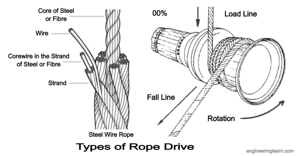
Wire rope is several strands of metal wire twisted into a helix forming a composite rope, in a pattern known as laid rope. Larger diameter wire rope consists of multiple strands of such laid rope in a pattern known as cable laid.
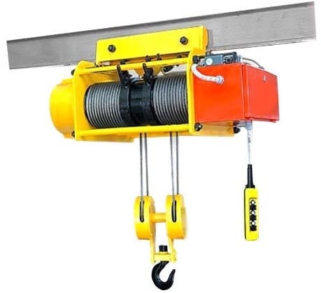
In the lifting and rigging industries, wire rope is attached to a crane or hoist and fitted with swivels, shackles or hooks to attach to a load and move it in a controlled matter. It can also be used to lift and lower elevators, or as a means of support for suspension bridges or towers.
Wire rope is a preferred lifting device for many reasons. Its unique design consists of multiple steel wires that form individual strands laid in a helical pattern around a core. This structure provides strength, flexibility, and the ability to handle bending stresses.
In stricter senses, the term wire rope refers to a diameter larger than 3/8 inch (9.52 mm), with smaller gauges designated cable or cords. Initially wrought iron wires were used, but today steel is the main material used for wire ropes.
Wire ropes are made from cold-drawn wires to increase strength and durability. It may be noted that as its size decreases the strength of the wire rope increases. The various materials used for wire ropes in order of increasing strength are iron, cast steel, extra-strong cast steel, steel, and alloy steel.
Wire ropes were developed starting with mining hoist applications in the 1830s. Wire ropes are used dynamically for lifting and hoisting in cranes and elevators, and for transmission of mechanical power.
It is also used to transmit force in mechanisms, such as a Bowden cable or the control surfaces of an airplane connected to levers and pedals in the cockpit.
A wire rope clip, sometimes called a u-bolt clamp or u-bolt clip is used to clamp the loose end of a length of wire rope, once it has been looped back to form an eye. These fittings consist of a u-bolt and has a saddle secured by two nuts.
The advantages of a wire rope are that they are more resistant to wear, have better crushing resistance, and high strength compared to a round strand wire rope of equal diameter and classification. However, a swaged wire rope may have less bending fatigue resistance.
Wire ropes are made from various grades of the steel wire with tensile strength ranging from 1200 to 2400 MPa. The wires are first given special heat treatment and then cold drawn for high strength and durability of the rope. Steel wire ropes are manufactured by specialized machines.
First, strands such as 7, 19, or 37 of the wire are routed into a strand, and then a number of strands, usually 6 or 8, are rotated about the core or center to form the rope. The core may be made of hemp, jute, asbestos, or soft steel wire. The core must be continuously saturated with lubricant for the long life of the core as well as the entire rope.
Asbestos or soft wire cores are used when the ropes are subjected to radiant heat such as cranes working near furnaces. However, a wire core reduces the flexibility of the rope, and such ropes are used only where they are subjected to high compressions. Such as in the case of the wounding of multiple layers on a rope drum.
Cross or Regular Laying Ropes: In these types of ropes, the direction of twisting of wires in the strides is opposite to the direction of the twist of the stand. These types of ropes are the most popular.
Parallel or lang lay ropes: In these types of ropes, the direction of rotation of the strands in the strands is similar to the strands in the rope. These ropes have a better bearing surface but are easily split and twisted when loaded. These ropes are more flexible and the wearer is more effective. Since such ropes have a tendency to rotate, they are used in lifts and waved by guide methods and also as rope ropes.
The direction of the laying of ropes can be right-handed or left-handed, depending on whether the strands form a right-handed or left-handed helix. But right-handed ropes are most commonly used.
Fibre ropes are made from fibres of varying length depending on their source. these are twisted up into yarns, and the twist given binds the fibres firmly together so that they hold by friction when the yarn is subjected to strain. The yarns are then laid up to form rope.
Ropes for transmission power are usually made of fibrous materials such as cannabis, manila, and cotton. Since hemp and manila fibres are rough, the ropes made of these fibres are not very flexible and have poor mechanical properties. The hemp rope has less strength than the Manila ropes.
When the hemp and manila ropes are bent over the sheave. The fibres cause some sliding, causing the rope to rub internally. To reduce this defect, rope fibres are lubricated with a tar, elongated, or graphite. Lubrication also makes the rope moisture-proof. Hemp ropes are suitable only for hand-operated hoisting machinery and for tackling rope tack, hooks, etc.
The cotton cord is very soft and smooth. Lubrication of cotton ropes is not necessary. But if it is done, it reduces the external wear between the rope and its edge grooves. It may be noted that Manila ropes are more durable and stronger than cotton ropes. Cotton ropes are more expensive than Manila ropes.
Manila and cotton ropes typically have a diameter of 38 mm to 50 mm. The size of the rope is usually specified by its circumference or ‘circumference’.
The ultimate tensile braking load of fibre ropes varies greatly. For Manila ropes, the average value of ultimate tensile braking load can be taken as 500 D 2 kN and for cotton ropes, it can be taken as 350 D 2 kN, where D is the diameter of the rope in mm.
Power transmission over long distances is the main application of rope drive. Rope drives are used to drive systems that are more than 8 meters in distance using a distance power transmission system. Metal ropes are used for distances beyond sixty meters. It is commonly seen in elevators and cranes.
Rope drive is a form of belt drive, which is used for mechanical power transmission. Rope drives use multiple circular section ropes instead of single flats or V-belts. The rope drives are widely used where a large amount of power is to be transmitted, from one pulley to another, over a considerable distance.
Wire rope is several strands of metal wire twisted into a helix forming a composite rope, in a pattern known as laid rope. Larger diameter wire rope consists of multiple strands of such laid rope in a pattern known as cable laid.
A wire rope clip sometimes called a u-bolt clamp or u-bolt clip is used to clamp the loose end of a length of wire rope, once it has been looped back to form an eye. These fittings consist of a u-bolt and have a saddle secured by two nuts.
The term cable is often used interchangeably with wire rope. However, in general, wire rope refers to diameters larger than 3/8 inch. Sizes smaller than this are designated as cable or cords. Two or more wires concentrically laid around a center wire is called a strand.
Available in various constructions, sizes and finishes, wire rope is a versatile material that can be used to (among other things) lift, hoist, separate, position, secure, remove, repair, readjust, support and brace items in a safe and effective manner. Wire rope was initially designed to assist in the mining industry.
Dyneema is the world’s strongest fiber-producing ropes that are 15 times stronger than steel wire ropes of the same weight and has become one the most trusted fiber ropes over generic HMPE ropes and steel cable wire ropes for all rigging, maritime, mooring, and towing rope applications.
Overall, wire rope is stronger than chain. The multi-strands of continuous wires give wire rope its strength, whereas a chain is joined together with links. These joins are the weakest part of a chain and can break under heavy loads.
Wire rope is a preferred lifting device for many reasons. Its unique design consists of multiple steel wires that form individual strands laid in a helical pattern around a core. This structure provides strength, flexibility, and the ability to handle bending stresses.
The various materials used for wire ropes are iron, cast steel, extra strong cast steel, steel, and alloy steel, in order of increasing strength. For some purposes, wire rope can also be made from copper, bronze, aluminum alloys, and stainless steel.
In general, the higher wire count of a 7×19 typically makes it a better choice for winches, garage doors, and other applications that require tighter and more frequent turns, while the rigidity of a 7×7 makes it a good choice for automotive and aircraft controls.
Braided rope is stronger and is nicer on the hands than twisted rope, but it’s a pain to splice yourself. This means if you’re using a windlass and chain, and you are doing your own splicing, you’ll probably need to use twisted rope.
6 x 19S (Seale) -This is a good rope to withstand abrasion or crushing on the drum but its fatigue resistance is decreased. 6 x 25FW (Filler Wire) – To most wire rope users, 6 x 19 means 6 x 25 filler wire. It is a common rope in the 6 x 19 classification.
A wire rope is stronger because the material that makes it is continuous, i.e. without joins. In a chain, individual links must be closed by joining their ends, and that reduces the tension it can handle.
Compared to chain, steel wire ropes have a higher strength-to-weight ratio, making them easier to install and lighter on the floating structure. Steel wire ropes are most commonly constructed of many thin steel wires wound into strands, which are then wound around a central core into the final wire rope.
You should generally use equipment with a working load limit that is rated for weight at least five times higher – or 250,000 lbs. in this case. This recommendation is all thanks to the wire rope safety factor.
A rope that has more strands exhibits greater flexibility than one with fewer strands. Crush resistance: Although wire rope with a fiber core offers the most flexibility, it also demonstrates less resistance to crushing. If crushing is not a concern but flexibility is, fiber core wire rope is ideal.
The helix or spiral of the wires and strands in a rope is called the lay. Regular lay denotes rope in which the wires are twisted in one direction, and the strands in the opposite direction to form the rope. … These ropes are more likely to twist, kink and crush than regular lay ropes.
Our team understands that choosing the right cable assembly manufacturer, and pulleys for your cable assemblies requires thoughtful consideration, from bearing life, to minimum pulley diameter. Let Sava"s engineering expertise guide you toward the best selection of wire rope pulley wheels.
When cable is used over pulleys, the cable life can be significantly prolonged by proper pulley groove design. Laboratory tests on wire rope pulleys prove that improper groove design reduces cable bending life up to 90%. These same tests show that doubling a pulley diameter can increase cable bending life up to thirteen times what is otherwise typical. Also, pulley diameters less than sixteen rope diameters fall into a range in which cable life is relatively low.

The purpose of the dimensioning of rope drives is, by application-specific interactions of safety factors and diameters of the rope drive elements, to ensure sufficient operating life of the wire ropes. For hoisting gear and cranes, this is done according to the DIN 15020 standard with mechanism groups and the direct calculation of the rope diameter. Using the “Leipzig” method simplified for the TGL 34 022 standard, it was possible to mathematically estimate the bending cycles of wire rope constructions for visible and non-visible wire breaking development in rope drives generally. The rope diameter was defined from the safety factor in conjunction with the required operating life. This was the first time that the “sufficient time of bearing” could be calculated for rope drives according to DIN 15020. The “Leipzig” method integrates the experimental results of the former WBK rope testing body Bochum. Comparisons with the “Stuttgart” method showed both differences and extensive agreement of bending cycles tolerated with mathematical probability. Rope drive analysis by means of a “rope harp shape” is a way of calculating the bending cycles acting in rope drives and other stresses from the operating conditions of the ropes. In the new preliminary standard DIN CEN/TS 13001-3-2, the rope diameter is defined from one of two limit design rope forces. The interactions resulting from the proof procedure continue the tradition of dimensioning according to DIN 15020. However, the method of calculating the total bending cycles could raise excessively optimistic expectations on the service life of the wire ropes in the interactions of dimensioning, and signs of fatigue not detected in time may cause risks or even rope breakage.

RF2FK0FHX–Lifting mechanism of an overhead crane with a hook and chain next to the reinforcement of iron structures in a workshop of an industrial enterprise.
RF2G8H3MG–Gear wheel and steel rope. Fragment of a crane or steel structure tension. The steel rope is in a good finish while the toothed wheel is clearly rusty
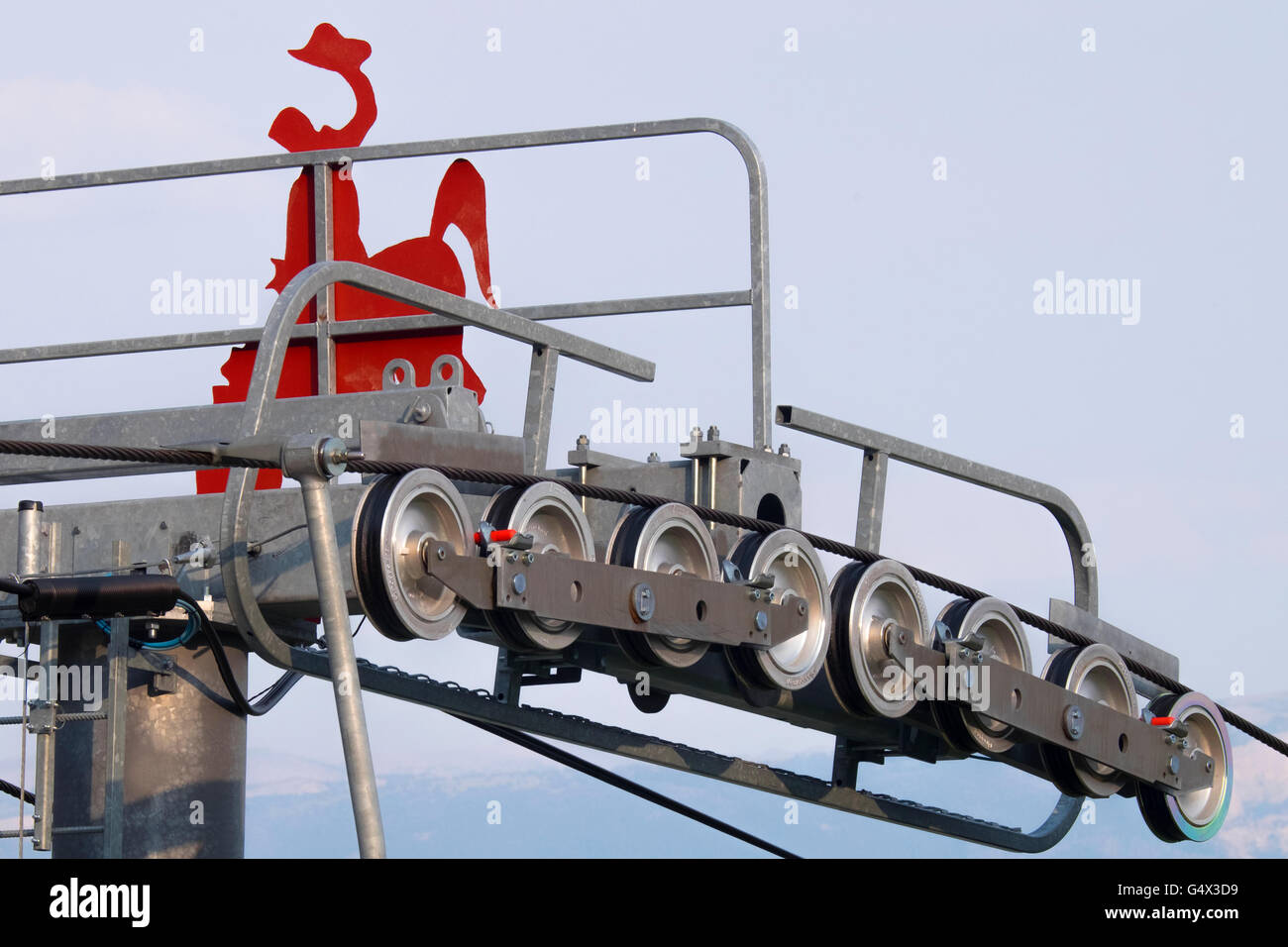
RFRX1A2E–The mechanism of the ski lift, visible large, driving wheel pulling the rope and suspended chairs in the background Tatra Mountains and trees.
RF2JCRJR4–Steel cable sling hoist hook with gears. Wire rope sling and crawler drum of lifting crane machine. Closeup selective focus industrial mechanism
RF2K7MTEK–Rusted Iron industrial reel with rope attached for the scaffolding with wires was installed to raising the cargo, a settlement with residential buildi
RF2G8H3PB–Gear wheel and steel rope. Fragment of a crane or steel structure tension. The steel rope is in a good finish while the toothed wheel is clearly rusty
RFRX1A09–The mechanism of the ski lift, visible large, driving wheel pulling the rope and suspended chairs in the background Tatra Mountains and trees.
RF2K7MTJH–Rusted Iron industrial reel with rope attached for the scaffolding with wires was installed to raising the cargo, blue sky is in the background.
RF2G8H3M6–Gear and steel rope and crank. Fragment of a crane or steel structure tension. The steel rope is in a good finish while the toothed wheel is clearly r
RF2K7MTA4–Rusted Iron industrial reel with rope attached for the scaffolding with wires was installed to raising the cargo, a settlement with residential buildi
RF2G8H3M0–Gear wheel and steel rope. Fragment of a crane or steel structure tension. The steel rope is in a good finish while the toothed wheel is clearly rusty
Global Steel Wire Rope Market is Segmented By Material(Carbon Steel, Stainless Steel, Alloy Steel), By Lay Type(Regular Lay, Lang Lay), By End-User(Marine, Sports and Leisure, Oil and Gas, Industrial, Mining, Construction, Others), and By Region (North America, Latin America, Europe, Asia Pacific, Middle East, and Africa) – Share, Size, Outlook, and Opportunity Analysis, 2022-2029
[210 Pages Report]The Global Steel Wire Rope Market size was worth US$ YY million in 2021 and is estimated to reach US$ YY million by 2029, growing at a CAGR of YY% during the forecast period (2022-2029).
Steel wire rope is made from several strands of metal wire twisted into a helix to form a rope in a pattern known as laid rope. The wire rope diameter consists of multiplying the strands of such laid rope in a pattern known as cable laid. In the initial days, wrought iron was used for wire ropes; however, steel is exclusively used for making wire rope in the modern age due to the corrosion-resisting properties of steel. Galvanized steel and stainless steel are some forms of steel used to make wire ropes.
Historically, wire rope evolved from chains made of wrought iron, which had a high mechanical failure rate. Structural flaws in the chain links or solid steel bars can lead to complete and catastrophic failure, whereas flaws in the wire rope made of steel are less critical since the other wires easily bear the load. Friction between the individual steel wires and strands causes mechanical wear and tear over the rope"s service life and helps compensate for minor failures during service life.
Wire ropes were developed for hoisting mining loads in the 1830s. Today, wire ropes are used for dynamic lifting and hoisting in industrial cranes and modern elevators and mechanical power transmission in belt drive systems. Wire ropes transmit force and motion in mechanisms such as controlling an aircraft connected to levers and pedals in the cockpit. Static wire ropes support structures such as suspension bridges or as support to towers. A suspension monorail relies on a wire rope to support the carriage upside down. High corrosion resistance, good thermal stability and high stress and strain bearing capacity are some of the desired characteristics of steel wire rope.
Increased infrastructural and construction activities mainly drive the demand for steel wire rope is a key driver for the market. The growing adoption of synthetic and composite ropes is a key factor in limiting the growth of this market.
New residential apartments, recreational centers, commercial spaces, bridges, stadiums, tunnels and mass transit systems are under construction globally. The building and construction industry is experiencing an unprecedented boom, which has created strong demand for good quality, high-performance building materials. Steel wire rope is used in commercial construction suspension bridges and industrial cranes. Almost all modern elevators use steel wire ropes for operation. Therefore, the increase in infrastructure and construction is a key driver for the growth of the global steel wire rope market.
Recent years have seen a rise in innovation in the wire rope industry. Companies use new materials and rope construction methods to increase product value and drive growth. The industry is witnessing the growing adoption of synthetic and composite materials for wire rope making.
Synthetic materials are cheaper to manufacture than steel. Synthetic ropes also float on water due to their low density, making them ideal for marine applications. Synthetic ropes are also corrosion-proof since they are made from non-metals. The use of carbon fiber composites is also increasing since carbon fiber has twice the strength of steel with half the corresponding weight. The rising use of synthetic and composite ropes is a key challenge for the growth of the global steel wire rope market.
The global steel wire rope market experienced uneven impacts on value chains in production and sales in 2021 due to the COVID-19 pandemic. Construction and industrial applications saw steep declines since government-imposed lockdowns and restrictions brought a prolonged halt to manufacturing and office work globally.
China, a major market for the construction industry, emerged from the lockdown relatively early, in June 2020 and demand showed encouraging signs of recovery towards the end of 2020. However, North America and Europe were hit by the second wave of the pandemic, thereby depressing demand. The global demand is expected to recover by early 2021. Many small and medium scale companies in the supply chain were facing bankruptcy due to a collapse in demand. Global demand is expected to recover by the end of 2021 fully. The short-term impact of the pandemic has been mild for the steel wire rope market. The demand for steel wire rope remains strong and is expected to grow gradually in the coming years.
The global steel wire rope market is segmented into material, lay type, end-user and region. The steel wire rope market is segmented into regular and lang lay based on lay type. The regular type leads this segmentation since it has the largest applications. Lang lay is generally only used for specialized high load-bearing applications.
Asia-Pacific is leading in the global steel wire rope market. Due to major ongoing large-scale infrastructure projects, the region has the largest market share. China is also the largest market for steel wire rope in the world. China has the largest construction industry in the world and is expected to add US$1.2 trillion to global construction output by 2030. Residential and commercial construction has seen a tremendous increase in China in the last two decades.
China is also funding the Belt and Road Initiative (BRI), undertaking large-scale infrastructure projects throughout the Asia-Pacific. Residential and commercial construction has seen a tremendous increase in China in the last two decades. India is also undertaking massive commercial construction to drive infrastructure-led economic growth.
China also is the largest producer of construction equipment in the world. Steel wire ropes have extensive use in construction equipment, such as elevators and industrial cranes. The Asia-Pacific will continue to have the largest market share in the global steel wire rope market in the coming years.
The global steel wire rope market is competitive due to the availability of a wide variety of wire ropes that cater to different types of end-use applications. Some of the major players contributing to the growth in the segment are Bekaert S.A., Cortland Limited, Samson Rope Technologies, Southern Ropes, Marlow Ropes, Teufelberger, WireCo World Group, Gustav Wolf GmbH, Lanex A.S. and Jiangsu Langshan Wire Rope Co., Ltd. The major market players adopt growth strategies such as new product launches, patenting new technologies, joint ventures and collaborations, contributing to the growth of the global industry.
Overview:Bekaert S.A. is a major steel processing company interested in wire transformation and coatings. The company operates in 45 countries globally. Bekaert S.A. was founded in 1880 and is headquartered in Zwevegem, Belgium.
Product Portfolio:Flexisteelis a durable high tensile steel wire rope designed for an elevator hoisting application. A thermoplastic coating is applied to the rope to ensure noiseless elevator operation.
Key Developments: In February 2020, Bekaert S.A. and AGRO started a joint venture in Colombia. AGRO is a major producer of high-quality springers that merged with Bekaert S.A. to produce high-end steel wire systems. The merger is expected to increase the supply of steel wire ropes in South America.
Visualize the composition of the steel wire rope market segmentation by the material, lay type, end-user and region, highlighting the critical commercial assets and players.

This invention relates generally to the field of mechanical systems for providing reciprocating, linear motion for a movable structure or work piece relative to a fixed structure or work piece. More particularly, the invention relates to a drive mechanism providing reciprocating, linear motion from rotational motion of a motor, using a novel cable or wire rope drive mechanism. The invention is susceptible to many possible uses and installations, examples being drive systems for use in automated instruments for processing biological samples, and stacking systems for stacking cards or card-like bodies in a tray, which happen to be of particular applications presently employed by the present inventors. However, other possible uses of the invention in different types of machines and systems will be apparent to persons skilled in the art from the following detailed description, and thus the invention relates, primarily, to reciprocating drive mechanisms for a moveable work piece. [0002]
Drive mechanisms for providing reciprocating, linear movement of a moveable work piece relative to a stationary work piece or structure are known. An example is described in the patent of Clifford W. Karl et al., U.S. Pat. No. 5,674,454, assigned to the assignee of the present invention. Generally, the "454 patent describes a stacking system for stacking flat, thin, card-like objects in a magazine. The stacking system has a moveable push plate that is used to stack the objects in the magazine. In FIG. 7 of this patent, a motor has a pinion gear with teeth which engage complementary teeth of a push rack that is coupled to the push plate. The rotation of the motor causes the push rack to move back and forth in a linear fashion, causing a push plate to move back and forth relative to the magazine and thereby providing a mechanism for stacking the objects in the magazine. [0004]
Other drive systems known in the art include Levine et al., U.S. Pat. No. 5,854,075, which describes a drive belt system for moving a carriage assembly relative to a magazine containing a plurality of slides. Other patents describing belt-type drive systems include Seto et al., U.S. Pat. No. 5,660,793; and Shindo et al., U.S. Pat. No. 5,470,533. Porte et al., U.S. Pat. No. 5,073,342, describes a simple reciprocating piston-acruated transfer mechanism. Forsstrom, U.S. Pat. No. 3,221,781 contemplates a similar type of arrangement for moving sample carriers about an analytical instrument. Other reciprocating belt and paddle-based drive mechanisms are described in the patent of William E. Seaton et al., U.S. Pat. No. 5,736,102, which is also assigned to the assignee of the present invention. [0005]
While the drive mechanism of the type described in the above-cited are work satisfactorily for many applications, the present invention is considered to be an improvement over these and other types of systems. The present drive mechanism and method is believed to provide improved reliability in extended use, and decrease the amount of maintenance for the user. Further, the design is quiet in operation. The design is easy to assemble and less costly to manufacture than systems based on the design of the above-cited Karl et al. patent. [0006] SUMMARY OF THE INVENTION
In a first aspect, a drive mechanism for providing reciprocating, liner motion for a movable work piece relative to a stationary work piece is provided. The drive system includes a motor rotating a drum in forward and reverse directions about a first fixed axis. The motor is fixedly mounted with respect to the stationary work piece, such as to a housing or other structure. The system further includes an elongate, substantially non-flexible cable having first and second ends, which are fixed with respect to the stationary work piece. The cable, which in a preferred embodiment takes the form of a wire rope, further comprises an intermediate portion extending between said first and second ends, with the intermediate portion being wound around the drum. [0007]
The drive mechanism of the invention can be installed in any type of system that may benefit from quiet, reliable operation of a reciprocating linear drive mechanism. Preferred embodiments would be in automated biological sample testing instruments, and in stacking systems for flat, thin card-like objects. However, the invention is not limited to such systems. [0010]
In another aspect of the invention, a method is provided for moving a moveable work piece relative to a stationary work piece using an elongate, substantially non-flexible wire rope or cable, the cable having a first end and a second end and an intermediate portion between the first and second ends. The method includes the step of attaching the first and second ends of said cable to a structure fixed with respect to the stationary work piece. The method includes the step of winding the intermediate portion of the cable about a drum coupled to a motor, with the motor fixed with respect to the stationary work piece. The intermediate portion of the cable is further wound around the first and second bearings, with the first and second bearings mounted to the moveable work piece such that the first bearing is positioned between the first end of the cable and the drum and the second bearing is positioned between the second end of the cable and the drum. The method includes the step of rotating the drum, whereby the step of rotating causes the first and second bearings to move relative to the drum and thereby move the moveable work piece relative to the stationary work piece.[0011]
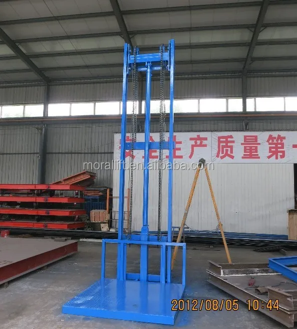
The purpose of this invention is to provide a kind of device that can realize that steel rope commutates and twines on reel, solve the problem that exists in the present rope luffing mechanism.
Technical scheme of the present invention is: this device is made up of reel, reverse wheel, luffing steel rope and compensation steel rope, luffing steel rope and compensation steel rope drive with same reel, compensation steel rope winding of single layer, the luffing steel rope divides two-layer winding, change winding direction by reverse wheel between the two-layer luffing steel rope, make the winding direction of two-layer luffing steel rope opposite, the winding direction of compensation steel rope is identical with ground floor luffing steel rope, the compensation steel rope is wrapped on the ground floor of luffing steel rope, with the space of the public second layer of second layer luffing steel rope.Utilization is wrapped in the formed plug helix of ground floor luffing steel rope outside face on the reel, the work grooving of steel rope and second layer luffing steel rope by way of compensation, and the hand of spiral of levels steel rope on reel is identical.
Ground floor luffing steel rope is used for jib was fallen, and second layer luffing steel rope is with the luffing of working.Because the winding direction of hoisting compensation steel rope is opposite with second layer luffing steel rope, be again to drive with same reel, so the order of folding and unfolding rope is opposite with second layer luffing steel rope, in work range, realized compensate function.When the maximum functional amplitude, the working portion of compensation steel rope all has been entangled on the reel, after second layer luffing steel rope has all been put, commutation through reverse wheel makes ground floor luffing steel rope devote oneself to work the reel contrarotation, ground floor luffing steel rope is emitted, the folding and unfolding order of compensation this moment rope also begins identical with the luffing rope, and luffing rope and compensation rope are emitted simultaneously, have realized the function that jib was fallen.
Effect of the present invention and benefit are: adopt the master screw slot reel, manufacturing cost is well below broken line reel.The hand of spiral of inside and outside two-layer luffing steel rope is identical, ground floor luffing steel rope twines along the master screw groove on the reel, second layer steel rope twines along the plug helix that the ground floor steel rope forms, and has avoided the intersection of two-layer steel rope, the life-span of having improved steel rope.Jib fell in the process, need not pull down the compensation steel rope, had reduced time and work capacity that jib fell, also need not increase independently to compensate the steel rope driver train, had reduced equipment cost.In work luffing scope, the reel moment that the compensation steel rope produces is opposite with the moment direction that the luffing steel rope produces, and has reduced the capacity of luffing mechanism electrical motor, has received good energy-saving effect.
From tank treads to bike gears to fishing lines, pulleys are used all over the place when it comes to mechanical transmissions. All types of pulley mechanisms consist of some sort of flexible belt (chain, cable, rope, etc.) turning around the circumference of a wheel, and pulleys can be incredibly useful in a variety of situations. In this Instructable I"ll go over some basic pulley concepts and interesting mechanisms, and hopefully you"ll be able to design your own pulley systems and make stuff like this!
The pulley is one of the six simple machines. Basically, all that a pulley is is a wheel spinning around an axle to aid the motion of a belt. The sprockets on a bike, for example, are a type of pulley, because when they spin, they drive other sprockets on the bike, that in turn rotate the rear wheel. So to make a basic pulley, all you need to do is loop a rope over some sort of wheel and axle.
Two pulleys can be used to create a simple belt and pulley system, in which a belt is looped between the two pulleys. One pulley is the "driving pulley", and as it spins, it transmits power through the belt either via friction or teeth, thus spinning a "driven pulley". I"ll be showing how you can use pulleys to make some pretty insteresting mechanisms later on.
Pulleys are probably most commonly used for lifting heavy loads and transmitting power across axes. Elevators, cranes, and boats all use pulleys because a pulley changes the direction of the applied force on the belt. Because the rope or belt is looped around the circumference of the pulley, the force of the object on one end of the rope can loop around the pulley to the other end. Certain types of pulley systems, like the block and tackle (to be explained later), can actually lessen the applied force needed to lift an object via a system of moving pulleys and lines, which can be very useful in high-load situations.
Pulleys are also one of a few different methods of transmitting rotation from one axis to another. Belts and pulleys can be used to transmit power over larger distances and in constricted spaces, which is one advantage they have over gears. Because most pulleys are driven by the friction between the pulley and the belt, if a part of a mechanism jams, then the belt transmitting power will slip on its pulleys instead of stalling the motor.
The speed ratio is equivalent to the reference diameter of the output pulley over the reference diameter of the input pulley in a two pulley system. Calculating the speed ratio of a more complicated pulley system is fairly simple as long as you take it step by step. With multiple pulleys, the ratio for each segment of the mechanism has to be calculated to determine the overall ratio. In the image above, the lower, driving pulley has a reference diameter of 20 mm and the upper pulley has a radius of 40 mm, making the ratio 2:1. It takes 2 rotations of the lower wheel to rotate the upper wheel once. The speed ratio also tells us something about the torque of the system, as the ratio of the output torque over the input torque is equal to the speed ratio. The upper wheel thus exerts twice the torque, but half the speed.
There are a few different types of pulleys that I"ll explain, which apply to multiple types of pulley systems. These the naming conventions for the basic types of pulleys. In future steps you"ll see how some of them can be applied to improve mechanisms.
Driving Pulley: The "input" pulley of a two-pulley system. This is the pulley whose shaft is being driven by something, like a motor, crank, or possibly by another pulley if in a larger system. This pulley is what is controlling the motion of the belt.
Idler Pulley:A type of driven pulley not meant to transmit power through its shaft. It spins freely, while most driven pulleys are linked to other devices, like wheels or actuators, via their drive shafts.
A belt and pulley system is one of the simplest types of pulley systems. As I described before, it contains two pulleys, one driving the belt and one driven by a belt. Belt drives can take many different forms; in tank treads, band saws, and sewing machines. Below are the four most common types of belts.
Timing Belt:Timing belts are like flat belts except they are toothed on their inside face. This allows for more precise control over the position of a mechanism, and it means that power is transmitted via the teeth instead of friction between the belt and pulley. As a result, timing belts don"t slip like other belts do, so the pulleys remain in sync. Some mechanisms, like XY gantries, use timing belts and mount parts to the belts to control their position.
Although we often refer to the sprockets on a bike as gears, chains mechanisms, like the ones on your bike, are actually pulley systems. The sprockets are just toothed pulleys, and each tooth catches in the link of a chain to pull the chain along. Here are some of the important things to know about chains:
A cable drive is a bit different than a belt or chain drive because the cable doesn"t have to be a continuous loop. The cable can be fixed at one end and free or attached to something else at the other. A fishing line is a great simple example of a cable system. The line is wrapped around a drum, and by spinning the pulley one way, you can let out the line, and spinning the pulley the other way, you can reel it in. Other things that use cable drive systems include cranes and some weightlifting machines.
Cable drives can be beneficial over belt or chain systems because they don"t need a continuous loop to operate, and the cable can be attached to things other than more pulleys. For example, a crane uses cable to pull in and let out the hook block it uses to lift loads. While belts and chain are usually the best for continuous rotational motion of two pulleys, cable drives can be useful because they can be used to manipulate the motion of mechanisms with smaller, slower movements, and these rotational motions can be easily translated to linear movements.
There are lots and lots of different types of pulley mechanisms out there, and this Instructable definitely doesn"t cover all of them. However, I hope this will give you a basic idea of some of the ways that you can use pulleys to improve your mechanical design techniques. I"ll be starting with some of the simplest mechanisms and design techniques and I"ll introduce some more complicated mechanisms, but not all of them. If you"re really interested in learning more, I would suggest you check out this book, 507 Mechanical Movements, as it comes with a lot of really neat mechanisms!
As I mentioned previously, the simple pulley is a wheel and axle with a rope or belt looped around it. As the rope is tugged, the pulley turns. The force on the rope travels around the pulley to the other end of the rope, so the pulley changes the direction of the force. If you were to attach a weight to one side of a rope, loop it around a pulley, and pull down on the other side of the pulley, the weight would lift up! It"s very simple. The direction of the force of your tug is changed from down to up.
A block and tackle is a cable system primarily found on cranes and boats that involves two pulleys and a cable or rope. The mechanism consists of one fixed pulley and one movable, usually hanging, pulley. A single rope is fixed to on or near the carriage of the fixed pulley, loops down and around the movable pulley, then back up and around the fixed pulley. A hook is attached to the underside of the movable pulley, and by tugging on the rope, the hook will lift or lower.
The beautiful thing about the block and tackle is that it decreases the force required to lift an object. As shown in the image above, the force of the object pulling down is split between the side of the rope with the fixed end and the free end. Thus when you pull on the free end, you only need to exert half the force that you would have had to exert with just a single pulley. The downside of the standard block and tackle is that the weight will only rise half as far as the distance you pull the rope, because the change in distance is split between the rope segment on the fixed end and the free end.
Block and tackle mechanisms can be stacked to incorporate multiple pulleys, which even further decreases the applied load required to lift a weight. Cable mechanisms in cranes frequently use this system to lift very heavy loads.
A belt and pulley system can transmit rotation and power to other axes over long distances and tight spaces. To do this with something like a gear mechanism, you either need a lot of gears, or very large gears, and that can ramp up the cost of a product pretty quickly. Another advantage of a belt and pulley system over a gear system is that the direction of rotation is conserved on a standard belt and pulley drive (although it can be altered). If the drive pulley spins a certain direction, the driven pulley will too. This is a big difference from gear mechanisms, in which two adjacent gears will turn in opposite directions.
Most pulley systems are friction based, which means that if the one side of a belt and pulley system jams,the belt can slip against the pulley if it needs to. Although this may sound bad, it is actually beneficial because it prevents the system from stalling out the motor by taking on too much torque. Band saws are a great example of this. The blade of the band saw is a large loop that acts as the belt, and two large pulleys turn the band saw to make it cut. If the blade were to catch badly on something, the saw would simply jam while the motor would keep turning the drive pulley.
Winches are mechanisms that allow you to wind up or unwind cable. They provide the basis for many large cable drive systems, because they consist of a large drum that can spool up the cable and can be used to collect slack. Many winches come with a ratcheting system that stops the drum from spinning if the cable is tugged on, which can be very useful in heavy lifting machines like cranes. A simple example of a winch is a fishing rod. When you cast out a rod, the ratchet is released and the line can extend freely. Once the ratchet is locked in place, any tug on the line will not turn the drum, but you can reel the line in to shorten it. A winch is a very simple, yet powerful cable drive mechanism.
Cross Belt Drive:The simplest method to invert rotation is by "flipping" one side of your belt so that the belt loop creates a figure 8. This is commonly seen in cable drive mechanisms. However, this technique cannot be applied to chain or belts with specific profiles, like V-belts or timing belts, because chains are not flexible enough, and the pulley would interface with the outside face of the belt. This technique may be tricky if the pulleys are close together.
Outside Pulley:A method common to chain driven mechanisms involves placing an idler sprocket on the outside of the chain loop. This can be done with belts too, except the pulley will be interfacing with the outside of the belt if this were to happen.
One of the great things about pulley systems is that they can be very modular, and you can make very simple mechanisms to create variable speeds and torques in a system. Here are a few different ways you can do this:
Speed Pulleys: This is pretty common in drill presses and lathes. By stacking pulleys of different diameters on top of one another, you can create different speed options just by sliding the belt onto a different set of pulleys. Each set of pulleys is paired such that the belt length and the distance between the pulleys" pivots stay the same while the speed ratio changes. This is similar to how a bike chain mechanism works, except on a bike a tensioner (which I"ll talk about soon) compensates for the slack on the chain.
Cone Pulleys:Cone shaped pulleys can be used to manipulate the speed as well. This system gives the user much more fine control over the speed ratio of the system, and is commonly used on milling machines and some other rotary tools. While stacking the pulleys allows for set ratios that need to be changed while the machine is stopped, with conical pulleys the belt can and should be moved while the mechanism is running, as the belt makes use of the spinning pulleys to slide up or down the pulleys. Cone pulleys usually work best with flat or round belts.
Note:You may not need or want to tension your belts all the time.If your mechanism isn"t going to spin at very high speeds, the pulleys are not very far apart, or your belt is elastic and thus self tensioning, you may not need to use a tensioning system on your mechanism. However, it"s never a bad idea.
Using some of the ideas from the mechanisms used to invert the rotation of the pulleys, we can transmit rotation from one axis to a perpendicular axis. Like the rotational inversion mechanisms, chain cannot be used on either of these mechanisms because chain isn"t flexible in the sideways direction.
To An Axis on the Same Plane:If you want to use a pulley system to transmit rotation from a driving axis to another axis on the same plane, you"ll need to feed the belt around two idler pulleys and onto the pulley you want to drive. The idler pulleys basically allow the belt to "bend" at a given angle to get to the driven pulley on the other side. This system can work with most belts and cable, although it will not work with timing belt pulleys because they aren"t very thick, and the idlers contact the side of the belt.
To An Axis on a different plane: To transmit rotation to an axis on a different plane, all you have to do is twist the belt! This requires wider pulleys, to give the belt space to wrap around, as the belt may come and leave contact with the pulley at an angle. This means that timing belts are unsuitable for use on this type of mechanism, because they require meshing with the teeth on timing belt pulleys.
The figure of 8 would not be possible for my application, as the belt would rub. The outside pulley method seems to be the least complicated option to change direction. I wonder, as the belt does not wrap around the idler pulley, how efficient would it be compared to the driven pulley? Would there be more chance of slippage, or would it be fine under enough tension? I could use it with a double sided timing belt for extra security. It would be moving about 5kg of weight, potentially.
Idler pulley is used to keep tension on system, it is always used on the "slack" or take up side and prevents a high speed belt from "whipping" and flying off the pulley or coming in contact with something. The tensioner is also used to aid in replacing the belt :loosen tensioner and the belt will just slide off the pulleys. and usually was taught in school that the number of lines in a block and tackle minus 1 (the end line has same advantage going up or down) was the machanical advantage or ratio of force to lift. It kinda makes sense looking at a picture of it but am not sure if there are systems that break that rule. You can make a block and tackle system with a single rope, a "Truckers cinch": Tie one end to a stationary object (bed of a truck) and throw line over load. Tie an "8" knot (make a 2 foot loop and tie it in a half hitch so you end up with a knot and loop in the middle of the rope) then run the tail of the rope to other side of the load, loop it around a stationary tie down and then run the rope back up through the loop. Bring it back down now and pull on it. youll exert 2X the pulling force (there is that 3 line rule), with the same effort as a one rope tie down system. If you have enough rope, you can make more loop backs and really put some tension on it but friction will eventually start to play a factor. This method is used for tensioning makeshift rope bridges.0
I believe that the idler pulley in Step 4 is meant as an example only. It, indeed, does not seem to serve any practical purpose. I"m not sure what is going on in Step 5 (or what that object even is?), but that doesn"t mean that the pulley isn"t serving some sort of function that I"m unaware of. Generally an idler pulley is used when you need to route around some other mechanical device that would otherwise be in the way of the belt. One of the best examples I can think of is a car engine, where your radiator hoses or A/C refrigerant lines need a somewhat direct route from Point A to Point B and requires re-routing of the drive belts to accommodate.0
In step 5, this is actually the inside of a giant pair of robotic googly eyes! As I also explained above, the idler pulley is serving as a tensioner because the belt is a bit larger than the distance around the driving and driven pulleys.0
Great question! I guess I didn"t show it clearly enough. Guide pulleys and idlers are very similar: guide pulleys are mostly used to guide cable through specific points to make it easier to route them along specific paths. Guide pulleys also frequently come in pairs. An idler pulley is also an unpowered pulley, and can be used to get the belt around corners and stuff like that, as lfoss mentioned, but can also be used to keep the belt taut, which is what is happening in the image in Step 5. The belt itself is too large to just wrap around the large pulley and the drive pulley and still drive the pulley effectively, so the idler pulley acts as basically a fixed tensioner to keep the belt tight around the other two pulleys. Does that make sense?0
Very nice, I inherited a drill press about a year ago and didn"t know about the variable speed drive mechanism up until a week ago (I"ve used it once). I just popped open the cover but haven"t taken the time to teach myself the theory behind the pulley system in there. Now I don"t have to, thanks!

Wire rope is a complex mechanical device that has many moving parts all working in tandem to help support and move an object or load. In the lifting and rigging industries, wire rope is attached to a crane or hoist and fitted with swivels, shackles or hooks to attach to a load and move it in a controlled matter. It can also be used to lift and lower elevators, or as a means of support for suspension bridges or towers.
Wire rope is a preferred lifting device for many reasons. Its unique design consists of multiple steel wires that form individual strands laid in a helical pattern around a core. This structure provides strength, flexibility, and the ability to handle bending stresses. Different configurations of the material, wire, and strand structure will provide different benefits for the specific lifting application, including:Strength
However, selecting the proper wire rope for your lifting application requires some careful thought. Our goal is to help you understand the components of a wire rope, the construction of wire rope, and the different types of wire rope and what they might be used for. This will allow you to select the best performing and longest-lasting wire rope for the job at hand.
A wire rope is, in reality, a very complicated machine. A typical 6 x 25 rope has 150 wires in its outer strands, all of which move independently and together in a very complicated pattern around the core as the rope bends. Clearances between wires and strands are balanced when a rope is designed so that proper bearing clearances will exist to permit internal movement and adjustment of wires and strands when the rope has to bend. These clearances will vary as bending occurs, but are of the same range as the clearances found in automobile engine bearings.
Understanding and accepting the “machine idea” gives a rope user a greater respect for rope, and enables them to obtain better performance and longer useful life from rope applications. Anyone who uses a rope can use it more efficiently and effectively when they fully understand the machine concept.
Wires are the smallest component of wire rope and they make up the individual strands in the rope. Wires can be made from a variety of metal materials including steel, iron, stainless steel, monel, and bronze. The wires can be manufactured in a variety of grades that relate to the strength, resistance to wear, fatigue resistance, corrosion resistance, and curve of the wire rope.
Strands of wire rope consist of two or more wires arranged and twisted in a specific arrangement. The individual strands are then laid in a helical pattern around the core of the rope.
The core of a wire rope runs through the center of the rope and supports the strands and helps to maintain their relative position under loading and bending stresses. Cores can be made from a number of different materials including natural or synthetic fibers and steel.
Lubrication is applied during the manufacturing process and penetrates all the way to the core. Wire rope lubrication has two primary benefits:Reduces friction as the individual wires and strands move over each other
The number of layers of wires, the number of wires per layer, and the size of the wires per layer all affect the strand pattern type. Wire rope can be constructed using one of the following patterns, or can be constructed using two or more of the patterns below.Single Layer – The most common example is a 7 wire strand with a single-wire center and six wires of the same diameter around it.
Filler Wire – Two layers of uniform-size wire around a center with the inner layer having half the number of wires as the outer layer. Small filler wires, equal to the number in the inner layer, are laid in valleys of the inner wire.
Seale – Two layers of wires around a center with the same number of wires in each layer. All wires in each layer are the same diameter. The large outer wires rest in the valleys between the smaller inner wires.
Warrington – Two layers of wires around a center with one diameter of wire in the inner layer, and two diameters of wire alternating large and small in the outer later. The larger outer-layer wires rest in the valleys, and the smaller ones on the crowns of the inner layer.
On a preformed wire rope, the strands and wires are formed during the manufacturing process to the helical shape that they will take in a finished wire rope.
Preformed rope can be advantageous in certain applications where it needs to spool more uniformly on a drum, needs greater flexibility, or requires more fatigue-resistance when bending.
Direction and type of lay refer to the way the wires are laid to form a strand (either right or left) and how the strands are laid around the core (regular lay, lang lay, or alternate lay).Regular Lay – The wires line up with the axis of the rope. The direction of the wire lay in the strand is opposite to the direction of the strand lay. Regular lay ropes are more resistant to crushing forces, are more naturally rotation-resistant, and also spool better in a drum than lang lay ropes.
Lang Lay– The wires form an angle with the axis of the rope. The wire lay and strand lay around the core in the same direction. Lang Lay ropes have a greater fatigue-resistance and are more resistant to abrasion.
A steel core can be an independent wire rope or an individual strand. Steel cores are best suited for applications where a fiber core may not provide adequate support, or in an operating environment where temperatures could exceed 180° F.
The classifications of wire rope provide the total number of strands, as well as a nominal or exact number of wires in each strand. These are general classifications and may or may not reflect the actual construction of the strands. However, all wire ropes of the same size and wire grade in each classification will have the SAME strength and weight ratings and usually the same pricing.
Besides the general classifications of wire rope, there are other types of wire rope that are special construction and designed for special lifting applications.
Some types of wire rope, especially lang lay wire rope, are more susceptible to rotation when under load. Rotation resistant wire rope is designed to resist twisting, spinning, or rotating and can be used in a single line or multi-part system.
Special care must be taken when handling, unreeling, and installing rotation resistant wire rope. Improper handling or spooling can introduce twist into the rope which can cause uncontrolled rotation.
Compacted strand wire rope is manufactured using strands that have been compacted, reducing the outer diameter of the entire strand, by means of passing through a die or rollers. This process occurs prior to closing of the rope.
This process flattens the surface of the outer wires in the strand, but also increases the density of the strand. This results in a smoother outer surface and increases the strength compared to comparable round wire rope (comparing same diameter and classification), while also helping to extend the surface life due to increased wear resistance.
A swaged wire rope differs from a compacted strand wire rope, in that a swaged wire rope’s diameter is compacted, or reduced, by a rotary swager machine after the wire rope has been closed. A swaged wire rope can be manufactured using round or compacted strands.
The advantages of a swaged wire rope are that they are more resistant to wear, have better crushing resistance, and high strength compared to a round strand wire rope of equal diameter and classification. However, a swaged wire rope may have less bending fatigue resistance.
A plastic coating can be applied to the exterior surface of a wire rope to provide protection against abrasion, wear, and other environmental factors that may cause corrosion. However, because you can’t see the individual strands and wires underneath the plastic coating, they can be difficult to inspect.
Plastic filled wire ropes are impregnated with a matrix of plastic where the internal spaces between the strands and wires are filled. Plastic filling helps to improve bending fatigue by reducing the wear internally and externally. Plastic filled wire ropes are used for demanding lifting applications.
This type of wire rope uses an Independent Wire Rope Core (IWRC) that is either filled with plastic or coated in plastic to reduce internal wear and increase bending fatigue life.
Remember, wire rope is a complex piece of mechanical machinery. There are a number of different specifications and properties that can affect the performance and service life of wire rope. Consider the following when specifying the best type of wire rope for your lifting application:Strength
When you select a piece of rope that is resistant to one property, you will most likely have a trade-off that affects another property. For example, a fiber core rope will be more flexible, but may have less crushing resistance. A rope with larger diameter wires will be more abrasion resistant, but will offer less fatigue resistance.
At Mazzella Companies, we offer all different kinds of wire rope from all of the leading manufacturers. We sell the highest-quality domestic and non-domestic rigging products because product quality and operating safety go hand-in-hand. We have one of the largest and most complete inventories of both domestic and non-domestic rigging and lifting products to suit your lifting needs.
If you’re looking for a standard or custom specified wire rope for your lifting project, contact a Lifting Specialist at a Mazzella Companies location near you.
We stock well over 2,000,000 feet of wire rope in our various locations … ready for immediate delivery! We provide wire rope assemblies, and manufacture bridge cables, crane cables, steel mill cables, and thousands of OEM assemblies.


 8613371530291