
wire rope drum groove design manufacturer

Drums are the means by which power is transmitted to the rope and thence to the object to be moved. For the wire rope to pick up this power efficiently and to transmit it properly to the working end, installation must be carefully controlled.
The end of the rope must be secured to the drum by such means as will give the end termination at least as much strength as is specified by the equipment manufacturer.
It is preferable to have at least three dead wraps remaining on the drum when the rope is unwound during normal operation. Three dead wraps are a mandatory requirement in many codes and standards.
If the wire rope is carelessly wound and, as a result, jumps the grooves, it will be crushed and cut where it crosses from one groove to the other. Another, almost unavoidable problem is created at the drum flange; as the rope climbs to a second layer there is further crushing and the wires receive excessive abrasion. Riser and filler strips may help remedy this condition.
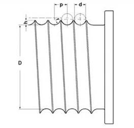
Another factor that must be given serious consideration is the pitch of the drum grooves relative to the actual rope diameter. Wire rope is normally manufactured to a plus tolerance. (See Table 3.) If this oversize tolerance in the rope is not taken into account, it can mean severe damage.
As an example, a grooved drum made for 1/4-inch rope may have a pitch of .250 inches. Yet, by Federal standards, a 1/4-inch rope may have a diameter as large as .265 inches. If a rope of this size were to be operated on a drum with a .250 inch pitch, crowding would occur and the rope would be forced out of the groove.
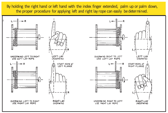
Installation of a wire rope on a plain (smooth) face drum requires a great deal of care. The starting position should be at the correct drum flange so that each wrap of the rope will wind tightly against the preceding wrap (Fig. 32). Here too, close supervision should be maintained during installation. This will help make certain that:
Loose and uneven winding on a plain (smooth) faced drum can, and usually does, create excessive wear, crushing and distortion of the rope. The results of such abuse are lower operating performance and a reduction in the rope’s effective strength. Also, for an operation that is sensitive in terms of moving and spotting a load, the operator will encounter control difficulties as the rope will pile up, pull into the pile and fall from the pile to the drum surface. The ensuing shock can break or otherwise damage the rope.
Changing out crane rope drums or replacing the wire rope is a demanding and time consuming operation for your maintenance team. Based on a study conducted by a technical association that supports the steel industry, the number one reason for replacing rope drums is wear of the grooves.
Wear can make the top surface of the separating land extremely sharp, creating the potential for cutting the wire rope. Wear or corregations in the base of the grooves prevent the wire rope from twisting properly; thus pinching and damaging the rope. The answer to address both of these problems is in the material and heat treatment of your rope drum.
Multi-layer drum systems should use strand- or swage compacted Python® rope constructions having a steel core. The higher fill factor of such rope constructions will offer a greater resistance to crushing and flattening than conventional rope types. This is particularly important for boom hoist ropes on lattice boom cranes at the cross over point from one rope winding to the next.
Cranes equipped with multi-layer drum systems which require rotation-resistant or non-rotating rope are best served with Python Compac® 18 and Compac® 35. To further reduce drum crushing have the rope layers wound onto the drum with about 5-10% of the WLL and avoid that the first layer unspools and re-spools without tension. This would cause a ‘soft’ bottom layer which will flatten the rope.
Generally, we recommend grooved drums only. The rope is spooled properly and positively. Depending on the drum/rope diameter relationship helix-grooved drums can be used for up to 3 layers without excessive rope wear. For applications with more than 3 layers (e.g. Mobile cranes) we recommend ‘Lebus’ grooving.
It has to be remembered, however, that rope service life on multiple layer drum systems will always only be a fraction of that compared with single layer helix-grooved drums.
If these values are applied to single layer grooved drums the maximum permissible rope-deflection angle for regular wire rope constructions is 4°. For non rotating /rotation-resistant ropes the maximum permissible deflection angle is 1.5° only.

The name LeBus has been around the oil field industry since it was just a blacksmith shop in 1900. LeBus started out by manufacturing speciality tools for the booming west Texas oil fields. Tool pushers and/or owners would see a specific need for a new tool and LeBus would forge the new tools on demand. Soon LeBus was into the manufacturing and selling of fishing tools, drill collars, tool joints and rotary bits. LeBus manufactured the "Eureka Pipe Wrench" and the "Slip Socket Overshot". The common element in each case was the hoisting machinery, specifically the drum and wire rope, which was the main "workhorse" of the drilling rig. LeBus noticed that the wire rope would not lay in a consistent pattern on the drum. This caused undue wear and scrubbing of the wire rope. Something better was on the horizon.
Performance of wire rope in a machine is affected by design of its sheaves and drums. Information about design of sheave and drum (diameter, the shape of the groove profiles and corresponding radius, the drum pitch and the fleet angle) is given in this article. Other useful technical information on wire ropes – measurement of diameter; generally accepted design factors; capacity of drums and reels; reserve strength; wire rope clips and wire rope end connections is also given in this article.
Rope breaking strength is determined in a standard test wherein fittings are attached to the ends of the rope and the rope is pulled in a straight line. If however, the rope passes over a curved surface (such as a sheave or pin) its strength is decreased. The amount of such reduction will depend on the severity of the bend as expressed by the D/d ratio where D is sheave / drum diameter and d is wire rope diameter. At smaller D/d ratios, the loss in strength increases quite rapidly.
It can be seen that, a rope bent around a pin of its own diameter will have only 50% of the strength attributed to it in the standard test. This is called "50% efficiency". Even at D/d ratios of 40, there may be a loss of up to 5%.
In view of above, relevant standard or statutory requirement shall be followed. In absence of such requirements, the diameter of drum or sheave shall not be less than that given in the table below.
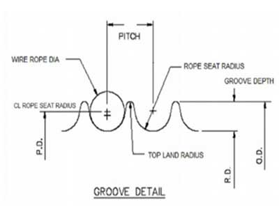
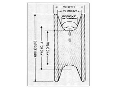
A too narrow groove will crush the rope and damage the wires soon. In too wide groove, the rope will wear more quickly at the point of contact and also cut a false groove in the pulley. In wide groove, the rope will not have lateral support and it will flatten under load. A rope shall be supported by the groove for one third of its circumference. Recommended groove dimensions for sheave and drum are as under.
The cranes are designed for four mechanism classes (Class 1 to 4) based on different duty factors (for strength and wear) and average life (running time per day and total life). For more information on various terms, please refer the specification.
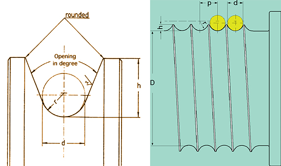
The contour at the bottom of the grooves shall be circular over an angle of approximately 120 degrees. The depth of the groove shall be not less than 0.35 times the diameter of the rope. The grooves of the drum shall be so pitched that there is, between adjacent turns of the rope, a clearance of not less than:
Sheaves shall be grooved to a depth of not less than 1.5 times the diameter of the rope. The contour at the bottom of the grooves shall be circular over an angle of approximately 130 degrees.
Where a wire rope leads over a sheave and on to a drum, the rope will not remain in alignment with the sheave but will deviate to either side depending on the width of the drum and the distance from the fixed sheave.
The fleet angle is the angle created at the point of intersection of a line drawn from the inside edge of the drum flange and along the centre line of the rope lead, and a line drawn from the centre of the drum at right angle to it. This angle is formed at the lead pulley. On a crane fitted with a grooved drum the angle should never exceed 4 degree and on a crane fitted with a flat-faced drum the angle should be between ½ degree and 2 degree maximum. If this angle is more, there will be heavy wear of the rope and groove sides.
To ensure the correct fleet angle, the following formula may be useful in finding the height of the lead pulley or the width of the drum, when one of these two measurements is known.
Diameter of a wire rope is the diameter of a circle circumscribing the strands. Care should be taken to see that it is measured correctly as shown above. The actual diameter usually varies from the nominal diameter of a rope. As per IS 2266, actual diameter can vary by -1% to 4 % of the nominal diameter of the rope.
When measuring the rope diameter, don"t measure the layer on the reel. Measure the rope when it is straight. To find the correct diameter at a point in a rope, the callipers must be placed over each pair of opposite strands, i.e. three separate readings for a six strand rope. The readings are then averaged.
The rope you are going to replace may be worn out and may measure less than the new rope. Measurement of rope to know its size shall be carried out where it is not worn out.
The reserve strength of a wire rope is the strength of the rope exclusive of the outer layer of wires, which are damaged. Following are the approximate reserve strengths expressed as a percentage of the total strengths of well lubricated new ropes.
Wire rope clips serve as an alternative to splicing and are a simple mechanical means of securing a wire rope round a thimble. They are also known as Bulldog Clips.
Wire rope clips are made from two types of materials. They are malleable iron and drop forged steel. Malleable wire rope clips are to be used only for non-critical, light duty applications with small applied loads. They should not be used for lifting or suspending load.
Several types of end connections used for overhead lifting applications are shown below. All efficiency ratings are based on the difference between the actual breaking strength of a rope and the attained breaking strength with that specific fitting. The only fitting which attains 100% efficiency are spelter sockets; provided they are properly attached.
Most of wire ropes have an actual breaking strength up to approximately 5%-15% higher than the breaking strength listed in catalogue. Due to this, wire ropes with even swaged fittings don’t fail at listed breaking strength and some manufacturers claim their assembly to have 100 % efficiency.

Performance of wire rope in a machine is affected by design of its sheaves and drums. Information about design of sheave and drum (diameter, the shape of the groove profiles and corresponding radius, the drum pitch and the fleet angle) is given in this article. Other useful technical information on wire ropes – measurement of diameter; generally accepted design factors; capacity of drums and reels; reserve strength; wire rope clips and wire rope end connections is also given in this article.
Rope breaking strength is determined in a standard test wherein fittings are attached to the ends of the rope and the rope is pulled in a straight line. If however, the rope passes over a curved surface (such as a sheave or pin) its strength is decreased. The amount of such reduction will depend on the severity of the bend as expressed by the D/d ratio where D is sheave / drum diameter and d is wire rope diameter. At smaller D/d ratios, the loss in strength increases quite rapidly.
It can be seen that, a rope bent around a pin of its own diameter will have only 50% of the strength attributed to it in the standard test. This is called "50% efficiency". Even at D/d ratios of 40, there may be a loss of up to 5%.
In view of above, relevant standard or statutory requirement shall be followed. In absence of such requirements, the diameter of drum or sheave shall not be less than that given in the table below.
A too narrow groove will crush the rope and damage the wires soon. In too wide groove, the rope will wear more quickly at the point of contact and also cut a false groove in the pulley. In wide groove, the rope will not have lateral support and it will flatten under load. A rope shall be supported by the groove for one third of its circumference. Recommended groove dimensions for sheave and drum are as under.
The cranes are designed for four mechanism classes (Class 1 to 4) based on different duty factors (for strength and wear) and average life (running time per day and total life). For more information on various terms, please refer the specification.
The contour at the bottom of the grooves shall be circular over an angle of approximately 120 degrees. The depth of the groove shall be not less than 0.35 times the diameter of the rope. The grooves of the drum shall be so pitched that there is, between adjacent turns of the rope, a clearance of not less than:
Sheaves shall be grooved to a depth of not less than 1.5 times the diameter of the rope. The contour at the bottom of the grooves shall be circular over an angle of approximately 130 degrees.
Where a wire rope leads over a sheave and on to a drum, the rope will not remain in alignment with the sheave but will deviate to either side depending on the width of the drum and the distance from the fixed sheave.
The fleet angle is the angle created at the point of intersection of a line drawn from the inside edge of the drum flange and along the centre line of the rope lead, and a line drawn from the centre of the drum at right angle to it. This angle is formed at the lead pulley. On a crane fitted with a grooved drum the angle should never exceed 4 degree and on a crane fitted with a flat-faced drum the angle should be between ½ degree and 2 degree maximum. If this angle is more, there will be heavy wear of the rope and groove sides.
To ensure the correct fleet angle, the following formula may be useful in finding the height of the lead pulley or the width of the drum, when one of these two measurements is known.
Diameter of a wire rope is the diameter of a circle circumscribing the strands. Care should be taken to see that it is measured correctly as shown above. The actual diameter usually varies from the nominal diameter of a rope. As per IS 2266, actual diameter can vary by -1% to 4 % of the nominal diameter of the rope.
When measuring the rope diameter, don"t measure the layer on the reel. Measure the rope when it is straight. To find the correct diameter at a point in a rope, the callipers must be placed over each pair of opposite strands, i.e. three separate readings for a six strand rope. The readings are then averaged.
The rope you are going to replace may be worn out and may measure less than the new rope. Measurement of rope to know its size shall be carried out where it is not worn out.
The reserve strength of a wire rope is the strength of the rope exclusive of the outer layer of wires, which are damaged. Following are the approximate reserve strengths expressed as a percentage of the total strengths of well lubricated new ropes.
Wire rope clips serve as an alternative to splicing and are a simple mechanical means of securing a wire rope round a thimble. They are also known as Bulldog Clips.
Wire rope clips are made from two types of materials. They are malleable iron and drop forged steel. Malleable wire rope clips are to be used only for non-critical, light duty applications with small applied loads. They should not be used for lifting or suspending load.
Several types of end connections used for overhead lifting applications are shown below. All efficiency ratings are based on the difference between the actual breaking strength of a rope and the attained breaking strength with that specific fitting. The only fitting which attains 100% efficiency are spelter sockets; provided they are properly attached.
Most of wire ropes have an actual breaking strength up to approximately 5%-15% higher than the breaking strength listed in catalogue. Due to this, wire ropes with even swaged fittings don’t fail at listed breaking strength and some manufacturers claim their assembly to have 100 % efficiency.
Integral rope groove drum: rope drums with grooves cut directly into them (with or without bolted or welded flanges, as required).Winch drum with flange, the LBS groove is cut directly into the body of the drum, according to customers’ requirements, the flanges are either welded or screw-bolted. groove geometry is determined by rope construction, diameter and length, and by application. the drum has the required mounting dimensions for the actual operating conditions.
The split -type sleeve system consists of a pair of outer casings that are bolted or assembled on a smooth light cylinder, so that the outer surface of the cylinder becomes a grooved form, and the split sleeve is composed of a spiral groove and a parallel groove, and the groove is formed. The design conforms to the specific rope structure, diameter and length.
Ever since the development of wire rope, comprising multiple wire strands, spooling the wire has presented technical challenges. When wrapped in multiple layers, the upper layers have a tendency to crush the lower layers, while the lower layers have a tendency to pinch upper layers. The rubbing of rope against rope also has a tendency to cause wear.
These problems were addressed by Frank L. LeBus Sr., a supplier of drilling equipment to the oilfields of Texas, USA, who in 1938, patented the use of a groove bar on hoisting drums to guide the spooling of rope. Grooved shape steel segments were simply welded or screwed to existing plain steel drums.
While the Lebus family business continues to produce this equipment today, their patents have expired. The Lebus name, however, is a registered trademark owned by the Lebus family business so the term "Lebus Drum" specifically refers to products of Lebus International.
The multilayer wire rope spooling system has undergone continuous refinement over the years and adapted for any application where long lengths of steel wire ropes must be wrapped in multiple layers quickly and smoothly. Examples include:
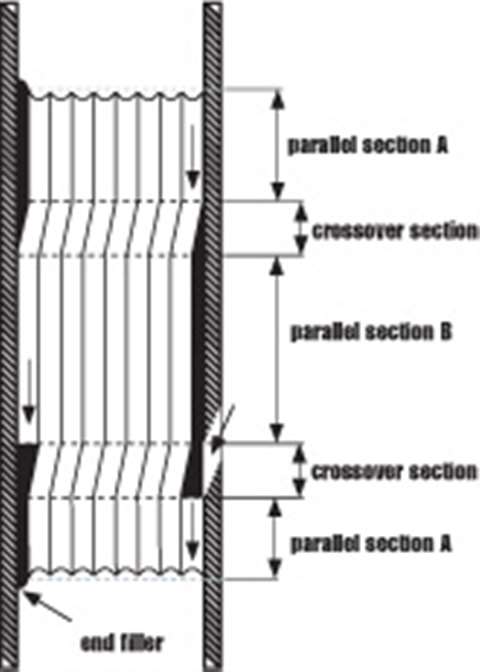
When the first layer has filled the drum, the second layer then travels back across the drum with each wrap of rope sitting precisely along the groove of two wraps of the first layer.
Cross winding is reduced to approximately 20% of the circumference of the drum, and 80% remains parallel to the flanges in the inner layer rope groove.
This parallel grooving evenly distributes the load between the individual layers and has been shown to increase substantially – by more than 500%, tests have shown – the life of the wire rope. The system has been used to mount ropes up.
In offshore applications, huge lengths of rope are often housed on drums. The anchor winches on Saipem"s Semac 1 pipe laying barge, for example, each hold 2,800 metres of 76mm (3 inch) diameter wire rope in 14 layers. Saipem"s Castorone, the world"s largest pipe laying vessel uses a wire rope that is 3,850m long and 152mm in diameter. It weighs 420t. The rope is pulled by capstan and stored on a massive Rema traction winches that feature the parallel grooving system, with an approximately back tension of 40t on the capstan.
Every system should be tailored to the application for which it is used. The groove pattern is engineered to suit the rope"s length, diameter and construction type.
In any multi-layer spooling application it is important that when the rope is first installed on the drum, it is done so under tension to avoid any slack on inner layers that can be crushed or nicked against the groove walls by outer layers.
The fleet angle is defined as the largest angle of the rope between the first sheave and the drum flange, relative to the centre line of the drum. With all type of drums, the rope is subject to a fleet angle which impacts on its behaviour and affects lifespan.
Fleet angle should be between 0.25° and 1.25°, depending on the rope construction. The fleet angle can be varied by moving the first sheave closer to or further away from the drum. If the sheave is too close to the drum, the fleet angle will be greater than 1.25°; if it is too far away, the fleet angle will be less than 0.25°.
Sometimes it is not possible to achieve the optimum fleet angle. Where there is no space to rig a sheave the requisite distance from the drum, two additional spooling devices are available. One is a fleet angle compensator, which is driven automatically by the rope tension. The other is a level winder that is mechanically driven. Both offer a solution to guide the cable along the drum between flanges, but each has its advantages and disadvantages.
The fleet angle compensator (FAC) is driven by the movement of the wire rope as it goes through the crossover sections of the drum. As the rope winds or unwinds, the FAC shaft automatically oscillates slowly, allowing its sheave to slide back and forth across the shaft to maintain an optimum fleet angle and guide the rope smoothly onto the drum.
Level winders can be hydraulically or electrically driven and computer controlled, or they can be simple mechanical devices. A mechanical level winder comprises a main shaft (the lead screw) with helical screw grooving along which the rope feeder travels. The rope feeder housing includes two vertical roller bars and one horizontal roller, or alternatively a wire rope sheave. The lateral movement of the housing is generated by a chain drive sprocket ratio between drum and lead screw, as shown in the image. The automatic level winder fitted is designed and engineered to be compatible with the grooving on the drum.
Oceanographic installations that spool rope up to 46 layers have demonstrated that level winders give synchronized and controlled spooling in the harshest, most testing conditions.
Grooving systems for multilayer spooling can be carved onto steel shells that are mounted onto old drums, by either bolting or welding, as an outer sleeve. Called split sleeves, they can be retrofitted onto old drums or mounted on new drums to allow a future change of application.


 8613371530291