
wire rope drum groove design supplier
Drums are the means by which power is transmitted to the rope and thence to the object to be moved. For the wire rope to pick up this power efficiently and to transmit it properly to the working end, installation must be carefully controlled.
The end of the rope must be secured to the drum by such means as will give the end termination at least as much strength as is specified by the equipment manufacturer.
It is preferable to have at least three dead wraps remaining on the drum when the rope is unwound during normal operation. Three dead wraps are a mandatory requirement in many codes and standards.
If the wire rope is carelessly wound and, as a result, jumps the grooves, it will be crushed and cut where it crosses from one groove to the other. Another, almost unavoidable problem is created at the drum flange; as the rope climbs to a second layer there is further crushing and the wires receive excessive abrasion. Riser and filler strips may help remedy this condition.
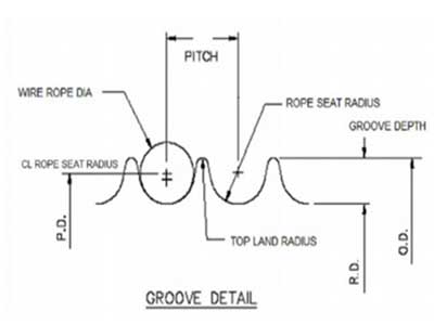
Another factor that must be given serious consideration is the pitch of the drum grooves relative to the actual rope diameter. Wire rope is normally manufactured to a plus tolerance. (See Table 3.) If this oversize tolerance in the rope is not taken into account, it can mean severe damage.
As an example, a grooved drum made for 1/4-inch rope may have a pitch of .250 inches. Yet, by Federal standards, a 1/4-inch rope may have a diameter as large as .265 inches. If a rope of this size were to be operated on a drum with a .250 inch pitch, crowding would occur and the rope would be forced out of the groove.
Installation of a wire rope on a plain (smooth) face drum requires a great deal of care. The starting position should be at the correct drum flange so that each wrap of the rope will wind tightly against the preceding wrap (Fig. 32). Here too, close supervision should be maintained during installation. This will help make certain that:
Loose and uneven winding on a plain (smooth) faced drum can, and usually does, create excessive wear, crushing and distortion of the rope. The results of such abuse are lower operating performance and a reduction in the rope’s effective strength. Also, for an operation that is sensitive in terms of moving and spotting a load, the operator will encounter control difficulties as the rope will pile up, pull into the pile and fall from the pile to the drum surface. The ensuing shock can break or otherwise damage the rope.

Generally, we recommend grooved drums only. The rope is spooled properly and positively. Depending on the drum/rope diameter relationship helix-grooved drums can be used for up to 3 layers without excessive rope wear. For applications with more than 3 layers (e.g. Mobile cranes) we recommend ‘Lebus’ grooving.
It has to be remembered, however, that rope service life on multiple layer drum systems will always only be a fraction of that compared with single layer helix-grooved drums.
If these values are applied to single layer grooved drums the maximum permissible rope-deflection angle for regular wire rope constructions is 4°. For non rotating /rotation-resistant ropes the maximum permissible deflection angle is 1.5° only.
Multi-layer drum systems should use strand- or swage compacted Python® rope constructions having a steel core. The higher fill factor of such rope constructions will offer a greater resistance to crushing and flattening than conventional rope types. This is particularly important for boom hoist ropes on lattice boom cranes at the cross over point from one rope winding to the next.
Cranes equipped with multi-layer drum systems which require rotation-resistant or non-rotating rope are best served with Python Compac® 18 and Python Compac® 35. To further reduce drum crushing have the rope layers wound onto the drum with about 5-10% of the WLL and avoid that the first layer unspools and re-spools without tension. This would cause a ‘soft’ bottom layer which will flatten rather quickly.

The name LeBus has been around the oil field industry since it was just a blacksmith shop in 1900. LeBus started out by manufacturing speciality tools for the booming west Texas oil fields. Tool pushers and/or owners would see a specific need for a new tool and LeBus would forge the new tools on demand. Soon LeBus was into the manufacturing and selling of fishing tools, drill collars, tool joints and rotary bits. LeBus manufactured the "Eureka Pipe Wrench" and the "Slip Socket Overshot". The common element in each case was the hoisting machinery, specifically the drum and wire rope, which was the main "workhorse" of the drilling rig. LeBus noticed that the wire rope would not lay in a consistent pattern on the drum. This caused undue wear and scrubbing of the wire rope. Something better was on the horizon.
Winch drum, hoist drum, and crane drum for sale from Dongqi Hoist and Crane, the manufacturer and supplier of types of cranes, electric hoists, winches, at good price. Dongqi offer custom winch drum design, hoist drum design, and crane drum design for your need. Which do you need, winch drum hoist drum or crane drum?
The biggest advantage of the Polygonal line drum is that it maximally protects the wire ropes that are wound on the reel, minimizing the point of contact between the strands, thereby extending the service life of the wire rope.
Dongqi Hoist and Crane can design types of drums for hoist, winch, and crane. In the following, the winch drum, hoist drum, and crane drum in Dongqi"s electric winch, electric hoist, and types of cranes are presented for your reference.
Dongqi electric drum winch shop mainly offering you the Engineering / construction winch, Marine Winch and Mine Winch with the capacity of 1-800 ton, which can be customize to you application environment.
Dongqi Hoist and Crane has types of electric drum winch for you, such as,small electric drum winch, light duty winch, and heavy duty winch, rope electric drum winch, cable electric drum winch, hoist winch, mining industrial electric drum winch and other types of electric drum winch,etc. In the following, the hot electric wicnh will be presented for your reference, inculding, Variable speed electric drum winch for sale,Planetary electric drum winch for sale,Friction electric drum winch for sale,High speed winch for sale,Low speed electric drum winch for sale,Double drum electric drum winch for sale,Piling electric drum winch for sale, and Heavy duty winch, etc.
As a hoist manufacturer and supplier, Dongqi Hoist and Crane offers types of electric hoists for customers, mainly electric chain hoist and rope drum hoist, etc. Dongqi rope drum hoists offering includes single / double speed hoist, low headroom hoist, explosion proof hoist, safety hoist, etc. The hot rope drum hoists are presented for your referencef in the following:
Wire rope drum is a part of crane lifting mechanism which is used to full in, entwine, and store wire rope. The Wire rope drum is consisted of drum shaft, flange type annular gear, drum hub, bearings, bearing pedestal, etc. Every part of Wire rope drum is engineered and manufactured to meet the operational and safety requirements of industrial crane applications.
Wire rope drum is usually made of cast iron. However, on special occasions or based on your special requirements, Wire rope drum can directly weld with cast steel or steel plate. Customized Wire rope drum is available from Dongqi Hoist and Crane.
Winch drum, hoist drum, and crane drum for sale from Dongqi Hoist and Crane, the manufacturer and supplier of types of cranes, electric hoists, winches, at good price. Dongqi offer custom winch drum design, hoist drum design, and crane drum design for your need. Which do you need, winch drum, hoist drum or crane drum?
Performance of wire rope in a machine is affected by design of its sheaves and drums. Information about design of sheave and drum (diameter, the shape of the groove profiles and corresponding radius, the drum pitch and the fleet angle) is given in this article. Other useful technical information on wire ropes – measurement of diameter; generally accepted design factors; capacity of drums and reels; reserve strength; wire rope clips and wire rope end connections is also given in this article.
Rope breaking strength is determined in a standard test wherein fittings are attached to the ends of the rope and the rope is pulled in a straight line. If however, the rope passes over a curved surface (such as a sheave or pin) its strength is decreased. The amount of such reduction will depend on the severity of the bend as expressed by the D/d ratio where D is sheave / drum diameter and d is wire rope diameter. At smaller D/d ratios, the loss in strength increases quite rapidly.
It can be seen that, a rope bent around a pin of its own diameter will have only 50% of the strength attributed to it in the standard test. This is called "50% efficiency". Even at D/d ratios of 40, there may be a loss of up to 5%.
In view of above, relevant standard or statutory requirement shall be followed. In absence of such requirements, the diameter of drum or sheave shall not be less than that given in the table below.
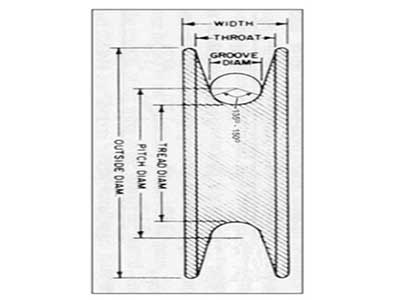
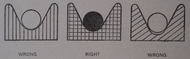
A too narrow groove will crush the rope and damage the wires soon. In too wide groove, the rope will wear more quickly at the point of contact and also cut a false groove in the pulley. In wide groove, the rope will not have lateral support and it will flatten under load. A rope shall be supported by the groove for one third of its circumference. Recommended groove dimensions for sheave and drum are as under.
The cranes are designed for four mechanism classes (Class 1 to 4) based on different duty factors (for strength and wear) and average life (running time per day and total life). For more information on various terms, please refer the specification.
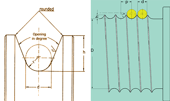
The contour at the bottom of the grooves shall be circular over an angle of approximately 120 degrees. The depth of the groove shall be not less than 0.35 times the diameter of the rope. The grooves of the drum shall be so pitched that there is, between adjacent turns of the rope, a clearance of not less than:
Sheaves shall be grooved to a depth of not less than 1.5 times the diameter of the rope. The contour at the bottom of the grooves shall be circular over an angle of approximately 130 degrees.
Where a wire rope leads over a sheave and on to a drum, the rope will not remain in alignment with the sheave but will deviate to either side depending on the width of the drum and the distance from the fixed sheave.
The fleet angle is the angle created at the point of intersection of a line drawn from the inside edge of the drum flange and along the centre line of the rope lead, and a line drawn from the centre of the drum at right angle to it. This angle is formed at the lead pulley. On a crane fitted with a grooved drum the angle should never exceed 4 degree and on a crane fitted with a flat-faced drum the angle should be between ½ degree and 2 degree maximum. If this angle is more, there will be heavy wear of the rope and groove sides.
To ensure the correct fleet angle, the following formula may be useful in finding the height of the lead pulley or the width of the drum, when one of these two measurements is known.
Diameter of a wire rope is the diameter of a circle circumscribing the strands. Care should be taken to see that it is measured correctly as shown above. The actual diameter usually varies from the nominal diameter of a rope. As per IS 2266, actual diameter can vary by -1% to 4 % of the nominal diameter of the rope.
When measuring the rope diameter, don"t measure the layer on the reel. Measure the rope when it is straight. To find the correct diameter at a point in a rope, the callipers must be placed over each pair of opposite strands, i.e. three separate readings for a six strand rope. The readings are then averaged.
The rope you are going to replace may be worn out and may measure less than the new rope. Measurement of rope to know its size shall be carried out where it is not worn out.
The reserve strength of a wire rope is the strength of the rope exclusive of the outer layer of wires, which are damaged. Following are the approximate reserve strengths expressed as a percentage of the total strengths of well lubricated new ropes.
Wire rope clips serve as an alternative to splicing and are a simple mechanical means of securing a wire rope round a thimble. They are also known as Bulldog Clips.
Wire rope clips are made from two types of materials. They are malleable iron and drop forged steel. Malleable wire rope clips are to be used only for non-critical, light duty applications with small applied loads. They should not be used for lifting or suspending load.
Several types of end connections used for overhead lifting applications are shown below. All efficiency ratings are based on the difference between the actual breaking strength of a rope and the attained breaking strength with that specific fitting. The only fitting which attains 100% efficiency are spelter sockets; provided they are properly attached.
Most of wire ropes have an actual breaking strength up to approximately 5%-15% higher than the breaking strength listed in catalogue. Due to this, wire ropes with even swaged fittings don’t fail at listed breaking strength and some manufacturers claim their assembly to have 100 % efficiency.
The majority of wire rope problems occurring during operation actually begin during installation, when the rope is at its greatest risk of being damaged. Proper installation procedures are vital in the protection and performance of wire rope products.
Until the rope is installed it should be stored on a rack, pallet or reel stand in a dry, well-ventilated storage shed or building. Tightly sealed and unheated structures should be avoided as condensation between rope strands may occur and cause corrosion problems. If site conditions demand outside storage, cover the rope with waterproof material and place the reel or coil on a support platform to keep it from coming directly in contact with the ground.
While lubrication is applied during the manufacturing process, the wire rope must still be protected by additional lubrication once it is installed. Lubricants will dry out over a period of time and corrosion from the elements will occur unless measures are taken to prevent this from happening. When the machine becomes idle for a period of time, apply a protective coating of lubricant to the wire rope. Moisture (dew, rain, and snow) trapped between strands and wires will create corrosion if the rope is unprotected. Also apply lubricant to each layer of wire rope on a drum because moisture trapped between layers will increase the likelihood of corrosion.
Always use the nominal diameter as specified by the equipment manufacturer. Using a smaller diameter rope will cause increased stresses on the rope and the probability of a critical failure is increased if the rated breaking strength does not match that of the specified diameter. Using a larger diameter rope leads to shorter service life as the rope is pinched in the sheave and drum grooves which were originally designed for a smaller diameter rope. Just as using a different diameter rope can create performance problems, so can the use of an excessively undersized or oversized rope.
Measure the wire rope using a parallel-jawed caliper as discussed in Measuring Rope Diameter at the top of this page. If the rope is the wrong size or outside the recommended tolerance, return the rope to the wire rope supplier. It is never recommended nor permitted by federal standards to operate cranes with the incorrect rope diameter. Doing so will affect the safety factor or reduce service life and damage the sheaves and drum. Note that in a grooved drum application, the pitch of the groove may be designed for the rope’s nominal diameter and not the actual diameter as permitted by federal standards.
Wire rope can be permanently damaged by improper unreeling or uncoiling practices. The majority of wire rope performance problems start here.Improper unreeling practices lead to premature rope replacement, hoisting problems and rope failure.
Place the payout reel as far away from the boom tip as is practical, moving away from the crane chassis. Never place the payout reel closer to the crane chassis than the boom point sheave. Doing so may introduce a reverse bend into the rope and cause spooling problems. Follow the guidelines highlighted under Unreeling and Uncoiling and Drum Winding. Take care to determine whether the wire rope will wind over or under the drum before proceeding. If the wire rope supplier secured the end of the rope to the reel by driving a nail through the strands, ask that in the future a U-bolt or other nondestructive tie-down method be used; nails used in this manner damage the rope.
Take extra precaution when installing lang lay, rotation-resistant, flattened strand or compacted ropes. Loss of twist must be avoided to prevent the strands from becoming loosened, causing looped wire problems.
The end of the rope must be securely and evenly attached to the drum anchorage point by the method recommended by the equipment manufacturer. Depending on the crane’s regulatory requirements, at least two to three wraps must remain on the drum as dead wraps when the rope is unwound during normal operations. Locate the dead end rope anchorage point on the drum in relation to the direction of the lay of the rope. Do not use an anchorage point that does not correspond with the rope lay. Mismatching rope lay and anchorage point will cause the wraps to spread apart from each other and allow the rope to cross over on the drum. Very gappy winding will occur resulting in crushing damage in multilayer applications.
Back tension must be continually applied to the payout reel and the crewman installing the rope must proceed at a slow and steady pace whether the drum is smooth or grooved.Regardless of the benefits of a grooved drum, tension must be applied to ensure proper spooling. An improperly installed rope on a grooved drum will wear just as quickly as an improperly installed rope on a smooth drum. If a wire rope is poorly wound and as a result jumps the grooves, it will be crushed and cut under operating load conditions where it crosses the grooves.
Every wrap on the first or foundation layer must be installed very tightly and be without gaps. Careless winding results in poor spooling and will eventually lead to short service life. The following layers of rope must lay in the grooves formed between adjacent turns of the preceding layer of rope. If any type of overwind or cross-winding occurs at this stage of installation and is not corrected immediately, poor spooling and crushing damage will occur.
On a multilayer spooling drum be sure that the last layer remains at least two rope diameters below the drum flange top. Do not use a longer length than is required because the excess wire rope will cause unnecessary crushing and may jump the flange. Loose wraps that occur at any time must be corrected immediately to prevent catastrophic rope failure.
The use of a mallet is acceptable to ensure tight wraps, however a steel-faced mallet should be covered with plastic or rubber to prevent damage to the rope wires and strands.
Rotation-resistant ropes of all constructions require extra care in handling to prevent rope damage during installation. The lay length of a rotation-resistant rope must not be disturbed during the various stages of installation. By introducing twist or torque into the rope, core slippage may occur—the outer strands become shorter in length, the core slips and protrudes from the rope. In this condition the outer strands become over- loaded because the core is no longer taking its designed share of the load. Conversely, when torque is removed from a rotation-resistant rope core slippage can also occur. The outer strands become longer and the inner layers or core become overloaded, reducing service life and causing rope failure.
The plain end of a wire rope must be properly secured. If the entire cross section of the rope is not firmly secured, core slippage may occur, causing the core to pull inside the rope’s end and allowing it to protrude elsewhere, either through the outer strands (popped core) or out the other end of the line. The outer layer of the outside strands may also become overloaded as there is no complete core-to-strand support.
Secure the ends of the rope with either seizing or welding methods as recommended under Seizing Wire Rope. It is imperative that the ends be held together tightly and uniformly throughout the entire installation procedure, including attaching the end through the wedge socket and the drum dead end wedge
When installing a new line, connect the old line to the new line by using a swivel-equipped cable snake or Chinese finger securely attached to the rope ends. The connection between the ropes during change-out must be very strong and prevent torque from the old rope being transferred into the new rope.Welding ropes together or using a cable snake without the benefit of a swivel increases the likelihood of introducing torque into the new rope. A swivel-equipped cable snake is not as easy as welding the ropes, but this procedure can be mastered with a little patience and practice.

Rope diameter is specified by the user and is generally given in the equipment manufacturer’s instruction manual accompanying the machine on which the rope is to be used.
Rope diameters are determined by measuring the circle that just touches the extreme outer limits of the strands— that is, the greatest dimension that can be measured with a pair of parallel-jawed calipers or machinist’s caliper square. A mistake could be made by measuring the smaller dimension.
The right way to unreel.To unreel wire rope from a heavy reel, place a shaft through the center and jack up the reel far enough to clear the floor and revolve easily. One person holds the end of the rope and walks a straight line away from the reel, taking the wire rope off the top of the reel. A second person regulates the speed of the turning reel by holding a wood block against the flange as a brake, taking care to keep slack from developing on the reel, as this can easily cause a kink in the rope. Lightweight reels can be properly unreeled using a vertical shaft; the same care should be taken to keep the rope taut.
The wrong way to unreel.If a reel of wire rope is laid on its flange with its axis vertical to the floor and the rope unreeled by throwing off the turns, spirals will occur and kinks are likely to form in the rope. Wire rope always should be handled in a way that neither twists nor unlays it. If handled in a careless manner, reverse bends and kinks can easily occur.
The right way to uncoil.There is only one correct way to uncoil wire rope. One person must hold the end of the rope while a second person rolls the coil along the floor, backing away. The rope is allowed to uncoil naturally with the lay, without spiraling or twisting. Always uncoil wire rope as shown.
The wrong way to uncoil.If a coil of wire rope is laid flat on the floor and uncoiled by pulling it straight off, spirals will occur and kinking is likely. Torsions are put into the rope by every loop that is pulled off, and the rope becomes twisted and unmanageable. Also, wire rope cannot be uncoiled like hemp rope. Pulling one end through the middle of the coil will only result in kinking.
Great stress has been placed on the care that should be taken to avoid kinks in wire rope. Kinks are places where the rope has been unintentionally bent to a permanent set. This happens where loops are pulled through by tension on the rope until the diameter of the loop is only a few inches. They also are caused by bending a rope around a sheave having too severe a radius. Wires in the strands at the kink are permanently damagedand will not give normal service, even after apparent “re-straightening.”
When wire rope is wound onto a sheave or drum, it should bend in the manner in which it was originally wound. This will avoid causing a reverse bend in the rope. Always wind wire rope from the top of the one reel onto the top of the other.Also acceptable, but less so, is re-reeling from the bottom of one reel to the bottom of another. Re-reeling also may be done with reels having their shafts vertical, but extreme care must be taken to ensure that the rope always remains taut. It should never be allowed to drop below the lower flange of the reel. A reel resting on the floor with its axis horizontal may also be rolled along the floor to unreel the rope.
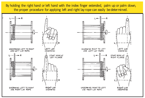
Wire rope should be attached at the correct location on a flat or smooth-faced drum, so that the rope will spool evenly, with the turns lying snugly against each other in even layers. If wire rope is wound on a smooth-face drum in the wrong direction, the turns in the first layer of rope will tend to spread apart on the drum. This results in the second layer of rope wedging between the open coils, crushing and flattening the rope as successive layers are spooled.
A simple method of determining how a wire rope should be started on a drum. The observer stands behind the drum, with the rope coming towards him. Using the right hand for right-lay wire rope, and the left hand for left lay wire rope, the clenched fist denotes the drum, the extended index finger the oncoming rope.
Clips are usually spaced about six wire rope diameters apart to give adequate holding power. They should be tightened before the rope is placed under tension. After the load is placed on the rope, tighten the clips again to take care of any lessening in rope diameter caused by tension of the load. A wire rope thimble should be used in the eye of the loop to prevent kinking.
U-bolt Clips.There is only one correct method for attaching U-bolt clips to wire rope ends, as shown in TheRightWayimage below. The base of the clip bears on the live end of the rope; the “U” of the bolt bears on the dead end.
Compare this with the incorrect methods. Five of the six clips shown are incorrectly attached—only the center clip in the top view is correct. When the “U” of the clip bears on the live end of the rope, there is a possibility of the rope being cut or kinked, with subsequent failure.
Proper seizing and cutting operations are not difficult to perform, and they ensure that the wire rope will meet the user’s performance expectations. Proper seizings must be applied on both sides of the place where the cut is to be made. In a wire rope, carelessly or inadequately seized ends may become distorted and flattened, and the strands may loosen. Subsequently, when the rope is operated, there may be an uneven distribution of loads to the strands; a condition that will significantly shorten the life of the rope.
Either of the following seizing methods is acceptable. Method No. 1 is usually used on wire ropes over one inch in diameter. Method No. 2 applies to ropes one inch and under.
Method No. 1: Place one end of the seizing wire in the valley between two strands. Then turn its long end at right angles to the rope and closely and tightly wind the wire back over itself and the rope until the proper length of seizing has been applied. Twist the two ends of the wire together, and by alternately pulling and twisting, draw the seizing tight.
The Seizing Wire. The seizing wire should be soft or annealed wire or strand. Seizing wire diameter and the length of the seize will depend on the diameter of the wire rope. The length of the seizing should never be less than the diameter of the rope being seized.
Proper end seizing while cutting and installing, particularly on rotation-resistant ropes, is critical. Failure to adhere to simple precautionary measures may cause core slippage and loose strands, resulting in serious rope damage. Refer to the table below ("Suggested Seizing Wire Diameters") for established guidelines. If core protrusion occurs beyond the outer strands, or core retraction within the outer strands, cut the rope flush to allow for proper seizing of both the core and outer strands.
The majority of wire rope problems occurring during operation actually begin during installation, when the rope is at its greatest risk of being damaged. Proper installation procedures are vital in the protection and performance of wire rope products.
Until the rope is installed it should be stored on a rack, pallet or reel stand in a dry, well-ventilated storage shed or building. Tightly sealed and unheated structures should be avoided as condensation between rope strands may occur and cause corrosion problems. If site conditions demand outside storage, cover the rope with waterproof material and place the reel or coil on a support platform to keep it from coming directly in contact with the ground.
While lubrication is applied during the manufacturing process, the wire rope must still be protected by additional lubrication once it is installed. Lubricants will dry out over a period of time and corrosion from the elements will occur unless measures are taken to prevent this from happening. When the machine becomes idle for a period of time, apply a protective coating of lubricant to the wire rope. Moisture (dew, rain, and snow) trapped between strands and wires will create corrosion if the rope is unprotected. Also apply lubricant to each layer of wire rope on a drum because moisture trapped between layers will increase the likelihood of corrosion.
Always use the nominal diameter as specified by the equipment manufacturer. Using a smaller diameter rope will cause increased stresses on the rope and the probability of a critical failure is increased if the rated breaking strength does not match that of the specified diameter. Using a larger diameter rope leads to shorter service life as the rope is pinched in the sheave and drum grooves which were originally designed for a smaller diameter rope. Just as using a different diameter rope can create performance problems, so can the use of an excessively undersized or oversized rope.
Measure the wire rope using a parallel-jawed caliper as discussed in Measuring Rope Diameter at the top of this page. If the rope is the wrong size or outside the recommended tolerance, return the rope to the wire rope supplier. It is never recommended nor permitted by federal standards to operate cranes with the incorrect rope diameter. Doing so will affect the safety factor or reduce service life and damage the sheaves and drum. Note that in a grooved drum application, the pitch of the groove may be designed for the rope’s nominal diameter and not the actual diameter as permitted by federal standards.
Wire rope can be permanently damaged by improper unreeling or uncoiling practices. The majority of wire rope performance problems start here.Improper unreeling practices lead to premature rope replacement, hoisting problems and rope failure.
Place the payout reel as far away from the boom tip as is practical, moving away from the crane chassis. Never place the payout reel closer to the crane chassis than the boom point sheave. Doing so may introduce a reverse bend into the rope and cause spooling problems. Follow the guidelines highlighted under Unreeling and Uncoiling and Drum Winding. Take care to determine whether the wire rope will wind over or under the drum before proceeding. If the wire rope supplier secured the end of the rope to the reel by driving a nail through the strands, ask that in the future a U-bolt or other nondestructive tie-down method be used; nails used in this manner damage the rope.
Take extra precaution when installing lang lay, rotation-resistant, flattened strand or compacted ropes. Loss of twist must be avoided to prevent the strands from becoming loosened, causing looped wire problems.
The end of the rope must be securely and evenly attached to the drum anchorage point by the method recommended by the equipment manufacturer. Depending on the crane’s regulatory requirements, at least two to three wraps must remain on the drum as dead wraps when the rope is unwound during normal operations. Locate the dead end rope anchorage point on the drum in relation to the direction of the lay of the rope. Do not use an anchorage point that does not correspond with the rope lay. Mismatching rope lay and anchorage point will cause the wraps to spread apart from each other and allow the rope to cross over on the drum. Very gappy winding will occur resulting in crushing damage in multilayer applications.
Back tension must be continually applied to the payout reel and the crewman installing the rope must proceed at a slow and steady pace whether the drum is smooth or grooved.Regardless of the benefits of a grooved drum, tension must be applied to ensure proper spooling. An improperly installed rope on a grooved drum will wear just as quickly as an improperly installed rope on a smooth drum. If a wire rope is poorly wound and as a result jumps the grooves, it will be crushed and cut under operating load conditions where it crosses the grooves.
Every wrap on the first or foundation layer must be installed very tightly and be without gaps. Careless winding results in poor spooling and will eventually lead to short service life. The following layers of rope must lay in the grooves formed between adjacent turns of the preceding layer of rope. If any type of overwind or cross-winding occurs at this stage of installation and is not corrected immediately, poor spooling and crushing damage will occur.
On a multilayer spooling drum be sure that the last layer remains at least two rope diameters below the drum flange top. Do not use a longer length than is required because the excess wire rope will cause unnecessary crushing and may jump the flange. Loose wraps that occur at any time must be corrected immediately to prevent catastrophic rope failure.
The use of a mallet is acceptable to ensure tight wraps, however a steel-faced mallet should be covered with plastic or rubber to prevent damage to the rope wires and strands.
Rotation-resistant ropes of all constructions require extra care in handling to prevent rope damage during installation. The lay length of a rotation-resistant rope must not be disturbed during the various stages of installation. By introducing twist or torque into the rope, core slippage may occur—the outer strands become shorter in length, the core slips and protrudes from the rope. In this condition the outer strands become over- loaded because the core is no longer taking its designed share of the load. Conversely, when torque is removed from a rotation-resistant rope core slippage can also occur. The outer strands become longer and the inner layers or core become overloaded, reducing service life and causing rope failure.
The plain end of a wire rope must be properly secured. If the entire cross section of the rope is not firmly secured, core slippage may occur, causing the core to pull inside the rope’s end and allowing it to protrude elsewhere, either through the outer strands (popped core) or out the other end of the line. The outer layer of the outside strands may also become overloaded as there is no complete core-to-strand support.
Secure the ends of the rope with either seizing or welding methods as recommended under Seizing Wire Rope. It is imperative that the ends be held together tightly and uniformly throughout the entire installation procedure, including attaching the end through the wedge socket and the drum dead end wedge
When installing a new line, connect the old line to the new line by using a swivel-equipped cable snake or Chinese finger securely attached to the rope ends. The connection between the ropes during change-out must be very strong and prevent torque from the old rope being transferred into the new rope.Welding ropes together or using a cable snake without the benefit of a swivel increases the likelihood of introducing torque into the new rope. A swivel-equipped cable snake is not as easy as welding the ropes, but this procedure can be mastered with a little patience and practice.

On multiple layer drums, wire rope will wear out at the crossover points from one wrap to the next. At these crossover points, the rope is subjected to severe abrasion and crushing as it is pushed over the rope ‘grooves’ and rides across the crown of the layer beneath. The scrubbing of the rope, as this is happening, can easily be heard.
In order to extend the rope’s working life, shortening of the rope at the drum anchoring point of approx. 1/3 of the drum circumference, moves the crossover point to a different section of the rope. Now, a rope section previously not subjected to scrubbing and crushing will take the workload.
During fabrication, ropes are lubricated; the kind and amount depending on the rope’s size, type and use, if known. This in-process treatment will provide the finished rope with ample protection for a reasonable time if it is stored under proper conditions, and in the early stages of the rope’s working life. It must be supplemented, however, at regular intervals.
Re-lubrication of a wire rope is not always a simple task. Apart from lubricant being a messy matter in itself, old lubricant, dirt and other particles may cover the outside of a rope to a point were any newly applied lubricant will not be allowed to penetrate the inside of a rope. In these cases it becomes necessary to either thoroughly clean the rope, or to use a high pressure lubrication device which forces new lubricant into the rope.
If the wire rope surface is clean, re-lubrication can also be made with spray cans of specially formulated lubricant which penetrates the inside of a rope.
The re-lubrication procedure and program is very much dependent on the length and size of a rope and on the equipment the rope is installed on. In any case, if a planned program of regular lubrication is not carried out, the rope will deteriorate more rapidly.
Remember that tests have shown that non-lubricated ropes will generate only about 1/3 of the bending cycles than ropes which are well lubicated. Python® ropes with a plastic coated core have the advantage that the inner rope is ‘permanently lubricated’; the lubrication is ‘sealed in’.
A common problem associated with wire rope is snagging on the winch drum, when an outer layer becomes trapped between wraps of underlying rope. Another common problem is damage to the lower layers caused by crushing from outer layers. With multiple layers of rope on a drum, the pressure on lower layers is immense.
In offshore applications, huge lengths of rope are often housed on drums. The anchor winches on Saipem"s Semac 1 pipe laying barge, for example, each hold 2,800 m of 76 mm diameter wire rope in 14 layers. It is bad enough having wire rope problems on a crane on a construction site, with the resulting replacement cost and lost time. Working offshore, though, the costs of rope or winching problems are huge.
The secret to avoiding problems, whatever the application, is to get the right drum. This means having it specially designed to specifically match the structure and length of the wire rope to be used.
Grooving on the face of the drum is commonly used to ensure that the rope spools smoothly and tidily. Where there is just a single layer of rope on the drum, a single helical groove, like the thread of a screw, will ensure the rope travels smoothly across the drum during spooling operations.
In multi-layer applications, however, a helical groove will result in additional layers of rope lying at an angle to lower layers, crosswise, and so risk crushing lower layers. This is where Lebus grooving comes into its own. It is a special grooving pattern developed in the 1950s by Frank LeBus, an American who supplied equipment to oilfields. In 1937 he had patented the use of a groove bar to guide the spooling of rope on hoist drums and later refined this to become what he called the LeBus Counterbalanced Spooling System. Though some companies have sought to imitate the Lebus system, the original is only produced by Lebus companies in the USA, Germany and the UK.
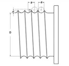
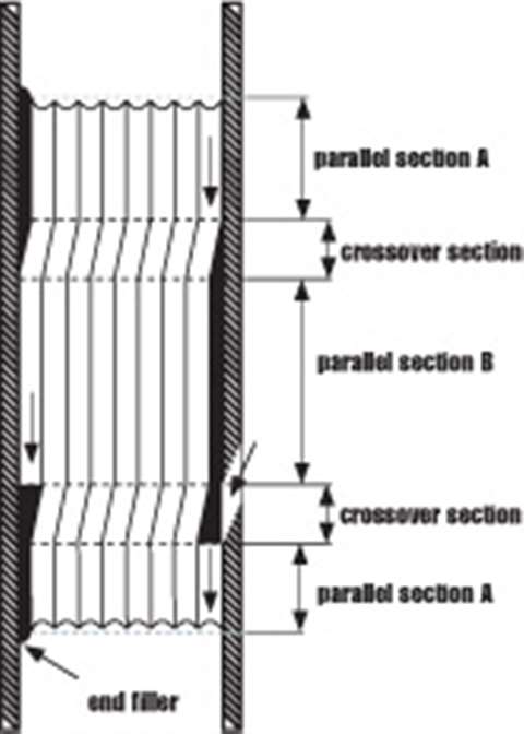
The Lebus grooving pattern has the grooves parallel to each other, and parallel to the flanges of the drum, with a crossover point on every groove on each side of the drum, (Figure 1). With this pattern, when the first layer has filled the drum, the second layer then travels back across the drum with each wrap of rope sitting precisely along the groove of two wraps of the first layer, (Figure 2).
With Lebus grooving it is possible to calculate the exact forces that the rope imposes on the drum because the spooling is totally controlled. This is not possible with any other spooling system.
Cross winding is reduced to approximately 20% of the circumference of the drum, and 80% remains parallel to the flanges in the inner layer rope groove.
This parallel grooving evenly distributes the load between the individual layers and has been shown to increase substantially – by more than 500% – tests have shown, the life of the wire rope.
Every Lebus system must be custom engineered. It is designed and produced specifically to meet the application for which it is used. The groove pattern is engineered to suit the rope"s length, diameter and construction type.
In any multi-layer spooling application it is important that when the rope is first installed on the drum, it is done so under tension to avoid any slack on inner layers that can be crushed or nicked against the groove walls by outer layers.
In general, the tighter the line, the better the spooling, but the rope should be tensioned with at least 2% of the breaking load or 10% of the working load. However, provision must also be made for the safety coefficient and the design of the cable. All subsequent spooling should also take place with the line under tension.
The fleet angle is the angle between the rope coming off the drum and the point at which it meets the first fixed sheave. Optimum fleet angle depends on the load, wire rope construction and line speed but our unrivalled experience has taught us that, as a good rule of thumb, it should generally never be any more than 1.5 degrees and no less than 0.5 degrees. Using these fleet angle guidelines means that for every 10 m that the drum is distanced from the sheave, the rope"s distance from the midpoint of the drum should never be more than 260 mm (520 mm between the flanges).
With helical grooved drums, the fleet angle can be up to 3 degrees, since the grooving is already at an angle to the flange, but only if the rope is wrapped in a single layer. If there is a second layer, such a large fleet angle will result in the rope cutting across too much and leaving gaps, which damages the rope.
When spooling a wire rope around a drum in multiple layers, the rope needs to be flexible enough to wrap tightly onto the drum, yet also sturdy, strong and rigid enough so that it does not suffer any deformation. Lebus has worked closely with all the major international wire rope manufacturers in developing optimum specifications for multi-layer applications.
Wire rope is a collection of metal strands that have been twisted and wound to form the shape of a helix with the purpose of supporting and lifting heavy loads and performing tasks that are too rigorous for standard wire. On shipping docks, rigging, and load bearing equipment, wire rope is attached to swivels, shackles, or hooks to lift a load in a controlled, even, and efficient manner.
The uses for wire rope include adding support to suspension bridges, lifting elevators, and serving as additional reinforcement for towers. The design of wire rope, with its multiple strands wrapped around a stable core, provides strength, flexibility, and ease of handling for applications that have bending stress.
Individual designs of wire rope involve different materials, wire, and strand configurations as a means for supporting and assisting in the completion of lifting or supportive applications.
The term wire rope encompasses a wide range of mechanical tools that are made to perform heavy and extreme lifting jobs. Wire rope is a complicated and complex tool with multiple moving parts capable of moving in unison. A 6 by 25 wire rope has 150 outer strands that move as one in an intricate pattern supported by a flexible core.
An essential part of the design of wire rope is the required clearance between the strands to give each stand the freedom to move and adjust when the rope bends. It is this unique feature that differentiates wire rope from solid wire and other forms of cable.
The basic element of wire rope is wire that is used to configure, shape, and form the rope. Typically, steel, stainless steel, and galvanized wires are the first choice with aluminum, nickel alloy, bronze, copper, and titanium being second possibilities. The choice of wire is dependent on the type of work the wire is going to be used to perform with strength, flexibility, and abrasion resistance being the major determining factors.
Stainless steel wire rope has all of the basic qualities of galvanized and general wire rope with the added benefits of corrosion and rust resistance; this makes it the ideal choice for harsh and stressful conditions.
Steel wire rope is classified as general purpose wire rope and comes in a wide variety of sizes, diameters, and strengths. It is the most common type of wire rope and is used for several industrial, manufacturing, and construction applications.
Before going further into the discussion of how wire rope is made, it is important to understand the numbers used to describe each type. All wire ropes have a core around which wires are wound. The various styles of cores vary according to the construction and design of the requirements of the wire rope that is being produced.
Wire rope is classified by the number of strands it has as well as the number of wires in each strand. The most common classification is a seven wire rope that has one strand in the center and six around its circumference. This type of wire rope is lightweight with a very simple construction. The majority of wire ropes are more complex and intricate with multiple intertwining strands and wires.
What must be understood about wire rope is that it has a complicated configuration. It is actually wires wrapped around wires to form bundles that are wrapped around other bundles. In the case of a seven wire wire rope, the core has bundles of wires wound around it; this can be seen in the image below.
The first step in wire rope creation is the production of wire strands where wires are wound around a single core wire. The number of wires included in the strand is dependent on the specified strength, flexibility, and size requirements of the rope. Once the strand is completed, it is straightened before being moved to wire rope construction.
Like wire ropes, strands have different patterns; patterns are the arrangements of the wires and their diameters. Though most strands have a core, there are strand patterns that have three or four wires without a core that are referred to as centerless strands. The design of each strand pattern is meant to enhance the strength of the wire rope and improve its performance.
For a multiple layer strand, the layers of wire are placed over one another in successive order. The placement of the wires on top of each other must be such that they fit smoothly and evenly.
The Warrington pattern is like the multiple layer pattern with one variation. Like the multiple layer pattern, the inner wires and the core are the same and have the same diameter. The difference is in the outer layer, which has wires of alternating sizes of large and small with larger diameter wires laying in the valleys of the inner wires.
All of the wires of a filler pattern are the same size. What makes this pattern unique is the insertion of small wires in the valleys of the inner wires to fill the gap between the inner and outer layer.
The flattened strand pattern is also known as the triangular strand, which can be triangular or oval. Three round wires form the core. The outer flattened surface has a greater sectional metallic area; this makes this pattern stronger and longer lasting.
The core of a wire rope runs through the center of the rope and can be composed of a variety of materials, which include synthetic fibers, natural fibers, a single strand, or another wire rope. The core supports the wound strands, helps maintain their position, is an effective lubricant carrier, and provides support.
Wire ropes with fiber cores are restricted to light loads and are not used in severe, harsh, or stressful conditions. Polypropylene and nylon are types of synthetic fiber cores and can be used in conditions where there is exposure to chemicals.
Cores made of wire are classified as independent wire cores. The core of a wire rope with a wire core is actually a wire rope with another wire rope serving as the core, as can be seen in the diagram below. These types of wire ropes are used where the rope will be exposed to exceptional resistance and crushing.
A strand, or wire strand core, is exactly like the rest of the strands of the wire rope with wires of the same diameter and size as the other strands.
The choice of core and creation of the strands are the simplest yet most essential parts of wire rope construction. Wire rope lays, the method used to wind the strands, is more complex and involves several choices.
Lay is a term used to describe three of the main characteristics of wire rope: direction, relationship, and linear distance. The strands can be wrapped around the core going right or left. Right or left refers to the direction of the strands wrapped around the core and the wires within the strands. The linear distance is how far a strand moves when it is making a revolution around the core.
In a regular lay, the wires and strands spiral in opposite directions. With a right hand regular lay, the wires spiral to the left and the strands to the right. In the left hand regular lay, the wires spiral to the right and the strands to the left. This type of lay is easy to handle but wears out quickly because the crown wires are in contact with the bearing surface.
In the Lang, or Albert, lay, the wires and strands spiral in the same direction with right hand lay being the most common. The wires in a Lang lay appear to run parallel to the center line of the rope. The difficulty with Lang lay wire ropes is handling since they tend to kink, twist, and crush.
Wire rope is an exceptionally strong tool that has been configured and designed to withstand the stress placed upon it through rigorous and continual use. In most applications, wire rope has to endure extreme stress and strain. It is for these reasons that coatings have been developed to protect wire rope from abrasions, corrosion, UV rays, and harmful and damaging chemicals.
Three main types of coatings are used to protect wire rope: polyvinyl chloride (PVC), polypropylene, and nylon. Of the three types, PVC is the most popular.
In cases where there are severe and hazardous working conditions, polypropylene is the recommended choice since it is capable of protecting wire rope against corrosion and chemical leaching. Additionally, it is resistant to impact damage and abrasion. Polypropylene is a tough, rigid, and crystalline thermoplastic that is made from a propene monomer and is resilient as well as inexpensive.
Braided wires are electrical conductors made up of small wires that are braided together to form a round tubular braid. The braiding and configuration of braided wire makes them very sturdy such that they do not break when flexed or bent. Braided wires are widely used as conductors, are commonly made from copper due to copper"s exceptional conductivity, and can be bare or coated depending on the application.
Braided wire can be round and tubular or flat. Round tubular braids fit in most spaces where flat braided wire will not. Flat braided wire begins as round braided wire which is flattened on a capstan. They are exceptionally strong and designed for medical and aircraft applications.
Metals used to make wire rope are various grades of stainless steel, bright steel, and galvanized steel. Though the majority of wire rope manufacturers use these three metals, other metals such as copper, aluminum, bronze, and monel are also used on a limited basis.
The most important aspect of wire rope is the wire and the metal from which it is made. The strength and resilience of wire rope is highly dependent on the quality of metal used to make it, and these are essential factors to be considered when purchasing it.
Bright steel wire does not have a coating and is rotation resistant, (designed to not rotate when lifting a load). It is drawn from hot rolled rods that are put through a die to match its specific dimensional tolerances, mechanical properties, and finish. Bright wire is used as a single line in conditions that require a rope that will resist cabling.
Galvanized steel has a zinc coating for corrosion resistance and has the same strength and durability as bright steel. Environmental conditions determine the use of galvanized steel. In mildly severe and slightly harsh conditions, galvanized steel wire is an economical replacement for stainless steel.
In the manufacturing process, galvanized wire goes through the process of galvanization, a method of coating steel wire with a protective and rust resistant metal. Galvanized wire is exceptionally strong, rust resistant, and flexible enough to meet the needs of a variety of applications.
Wire rope made from copper is mostly used for electrical applications due to its exceptional electrical characteristics. The benefits of copper wire rope are its durability, flexibility, and resilience compared to standard copper wire. The strength of copper wire rope is seen in its use in applications where there are vibrations and shaking.
The wire rope lubrication process begins during its fabrication and continues during its use. Lubrication of wire rope is designed to lower the amount of friction it endures and provide corrosion protection. Continued lubrication increases the lifespan of wire rope by preventing it from drying up, rusting, and breaking.
The types of lubricants for wire rope are penetrating or coating with coatings covering and sealing the outside of the rope. Penetrating lubricants go deep into the rope and seep into the core where they evaporate to form a thick coating or film.
The application of the lubricant is dependent on the type of core. Fiber cores absorb the lubricant and serve as a reservoir that retains the lubricant for an extended period of time. With metal cores, the lubricant is applied as the wire is twisted into strands to give complete saturation and coverage of the wires.
There are several types of greases that are used as wire rope lubricating agents and are made up of oil, a thickener, and additives. The essential components are the base oil and additives, which influence the behavior of the grease. The thickener holds the base oil and additives together. The amount of base oil in a grease is between 70% and 95% with an additive of 10%.
The additive in grease enhances the positive properties of the oil and suppresses the negative properties. Common additives are oxidation and rust inhibitors as well as pressure, wear, and friction reducing agents.
Of the many choices for lubricants, vegetable oil is the easiest to use and penetrates the deepest. The design of the additives for vegetable oils gives them the necessary qualities required to penetrate deep into a wire rope. The exceptional penetration provides protection against wear and corrosion. Since vegetable oil is a fluid, it helps in washing the wire rope to remove external abrasive contaminants.
Wire rope is widely used in machines, structures, and varied lifting applications. Its type, size, and requirements are determined by how it will be used. Regardless of its use, wire rope guarantees exceptional strength and provides high quality and excellent performance.
The lifting of heavy loads for centuries involved the use of hemp rope or chains, neither of which was a guaranteed or substantial method. Early in the 18th Century, between 1824 and 1838, Wilhelm Albert, a German mining engineer, combined the twisting of hemp and strength of chains to create today‘s wire rope.
The most common use of wire rope is as a part of a crane hoist wherein it is attached to the hook of the hoist and wrapped around a grooved drum. The tensile strength and durability of wire rope makes an ideal tool for lifting and keeping loads secure. Though it is used in several industries, it is very popular for production environments wherein materials need to be lifted quickly and efficiently.
In addition to its many lifting applications, the strength and stability of wire rope is useful in other applications, especially in the aerospace industry. Pedals, levers, and connectors in the cockpit of an aircraft are connected with wire rope. The wires provide for the passage of power between systems and mechanisms; this allows control of the aircraft. Wire rope is used to control propeller pitch, cowl flaps, and the throttle. It also assists in lowering and minimizing vibrations.
Tires are reinforced with wire rope to increase their durability and strength. All automotive production environments make use of wire ropes for supplying materials, moving heaving loads, and positioning equipment. Wire rope can be found in the production of steering wheels, cables, exhausts, springs, sunroofs, doors, and seating components.
As surprising as it may seem, the place that wire rope has the greatest use is in the home, where its strength, long life, endurance, and resilience provide guaranteed protection and performance. The main reason wire ropes are so popular for home use is cost.
Inexpensive, easy to obtain, easy to install, and easy to maintain, wire ropes provide an additional method for performing home repairs and structural support. Their excellent flexibility and sturdiness combined with their invisibility has made wire rope an ideal solution to several home maintenance issues. It is used to support staircases, fences, decks, and hang plants.
The search and production of crude oil has relied on wire ropes for centuries to lift drill bits, insert shafts, and support oil rigs on land and the water. When equipment, machinery, and tools have to be lowered into the depths of the earth and sea, wire ropes are the tool that the oil industry relies on to do the job.
Many of the tasks of oil production require tools that are capable of enduring severe and harsh conditions. Wire ropes have to withstand enormous pressure, extraordinary stress, and a wide range of temperatures. The use of wire rope includes maintaining oil rig stability and moorings for offshore rigs.
Wire rope has long been a standard component for the transportation industry, from the cable cars of San Francisco to the lift chairs for ski resorts. For many years, cable cars have relied on heavy duty cables (wire ropes) to be pulled by a central motor from multiple locations. It is a method of transportation that has existed for centuries.
In Europe, funiculars use cables that hang from a support to move cars up and down a mountain with cables moving in opposite directions. The word funicular is from the French word funiculaire, meaning railway by cable. The terms wire rope and cable are used interchangeably when discussed by professionals. The first part of funicular, or funiculaire, is from the Latin word "funis," meaning rope.
The major use for wire ropes in the food and beverage industries is as a means for lifting and moving heavy loads. Wine barrels and containers full of ingredients are lifted and placed through use of cranes and wire ropes. They are also part of conveyor systems that move products from one station to another.
From the beginnings of amusement rides up to the present, wire ropes have been an essential part of attraction construction and safety. They pull cars on roller coasters, hold cabins that swing, and move carriages through haunted houses. The main concern of amusement parks is safety. The strength, stability, and guaranteed performance of wire ropes ensures that people who attend amusement parks will have a good time and stay safe.
The rigging used to complete the stunts in modern movies depends on wire rope for safety. Much like in amusement rides, wire ropes protect performers from injury and harm as they hang above a scene or carry out an impossible move.
The live theater industry uses wire ropes to raise and lower curtains, support overhead rigging, and hold backdrops and scenery pieces. During a production, rapid and efficient movement is a necessity that is facilitated by the use of wire ropes.
Wire rope is a tool that we tend to envision as indestructible, unable to succumb to any form of damage. Though it is exceptionally sturdy and strong as well as capable of enduring constant use, it is just as susceptible to breakdown as any other tool.
To avoid serious harm and damage, wire ropes should be scheduled for regular inspections. There are situations that can damage or break a wire rope; these should be understood prior to the problem arising.
Guide rollers have the potential to damage and cause abrasions on wire rope if they become rough and uneven. Of the various elements of a crane and lift, guide rollers have the greatest contact with the mechanism‘s wire rope. Regular inspection of guide rollers will ensure they are not damaging the rope or causing abrasions.
Bending is normally a regular part of wire rope usage; this occurs repetitively as the rope passes through a sheave. As a wire rope traverses the sheave, it is continually bent and develops cracks or breaks. The cracking and breaking are exacerbated by movement on and off the groove of the drum. Normally, the breakage happens on the surface and is visible. Once it appears, it accelerates to the core of the rope.
A bird cage is caused by a sudden release of tension and a rebound of the rope. This type of break requires that the rope be replaced since the place of the break will not return to its normal condition.


 8613371530291