
wire rope failure osha free sample
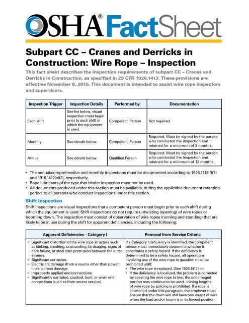
A competent person must begin a visual inspection prior to each shift the equipment is used, which must be completed before or during that shift. The inspection must consist of observation of wire ropes (running and standing) that are likely to be in use during the shift for apparent deficiencies, including those listed in paragraph (a)(2) of this section. Untwisting (opening) of wire rope or booming down is not required as part of this inspection.
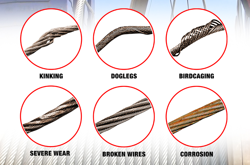
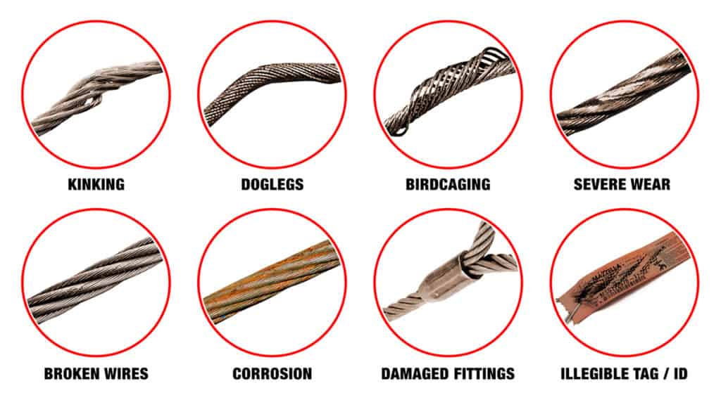
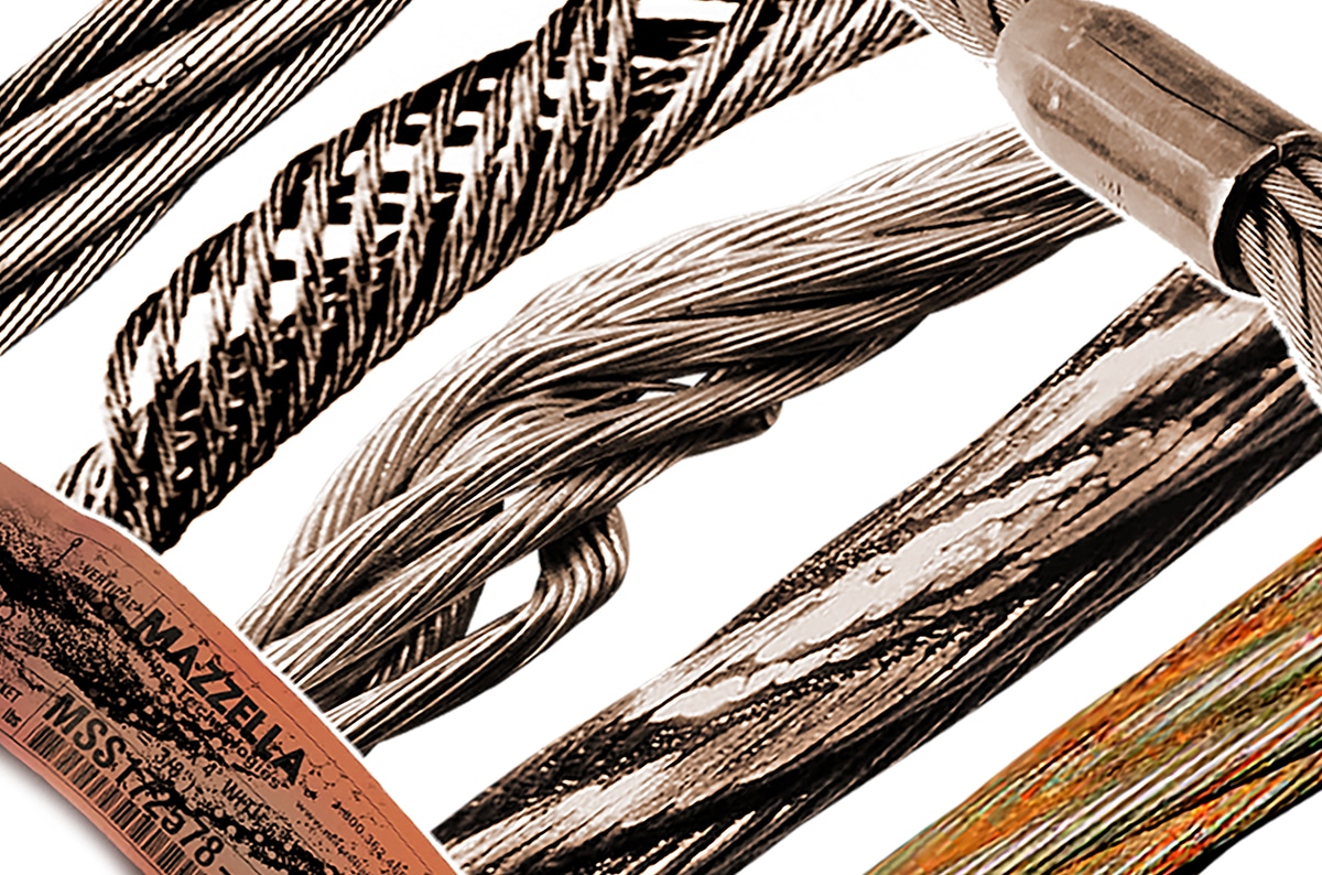
Significant distortion of the wire rope structure such as kinking, crushing, unstranding, birdcaging, signs of core failure or steel core protrusion between the outer strands.
In running wire ropes: Six randomly distributed broken wires in one rope lay or three broken wires in one strand in one rope lay, where a rope lay is the length along the rope in which one strand makes a complete revolution around the rope.
In rotation resistant ropes: Two randomly distributed broken wires in six rope diameters or four randomly distributed broken wires in 30 rope diameters.
In pendants or standing wire ropes: More than two broken wires in one rope lay located in rope beyond end connections and/or more than one broken wire in a rope lay located at an end connection.
If a deficiency in Category I (see paragraph (a)(2)(i) of this section) is identified, an immediate determination must be made by the competent person as to whether the deficiency constitutes a safety hazard. If the deficiency is determined to constitute a safety hazard, operations involving use of the wire rope in question must be prohibited until:
If the deficiency is localized, the problem is corrected by severing the wire rope in two; the undamaged portion may continue to be used. Joining lengths of wire rope by splicing is prohibited. If a rope is shortened under this paragraph, the employer must ensure that the drum will still have two wraps of wire when the load and/or boom is in its lowest position.
If a deficiency in Category II (see paragraph (a)(2)(ii) of this section) is identified, operations involving use of the wire rope in question must be prohibited until:
The employer complies with the wire rope manufacturer"s established criterion for removal from service or a different criterion that the wire rope manufacturer has approved in writing for that specific wire rope (see § 1926.1417),
If the deficiency is localized, the problem is corrected by severing the wire rope in two; the undamaged portion may continue to be used. Joining lengths of wire rope by splicing is prohibited. If a rope is shortened under this paragraph, the employer must ensure that the drum will still have two wraps of wire when the load and/or boom is in its lowest position.
If the deficiency (other than power line contact) is localized, the problem is corrected by severing the wire rope in two; the undamaged portion may continue to be used. Joining lengths of wire rope by splicing is prohibited. Repair of wire rope that contacted an energized power line is also prohibited. If a rope is shortened under this paragraph, the employer must ensure that the drum will still have two wraps of wire when the load and/or boom is in its lowest position.
Where a wire rope is required to be removed from service under this section, either the equipment (as a whole) or the hoist with that wire rope must be tagged-out, in accordance with § 1926.1417(f)(1), until the wire rope is repaired or replaced.
Wire ropes on equipment must not be used until an inspection under this paragraph demonstrates that no corrective action under paragraph (a)(4) of this section is required.
At least every 12 months, wire ropes in use on equipment must be inspected by a qualified person in accordance with paragraph (a) of this section (shift inspection).
The inspection must be complete and thorough, covering the surface of the entire length of the wire ropes, with particular attention given to all of the following:
Exception: In the event an inspection under paragraph (c)(2) of this section is not feasible due to existing set-up and configuration of the equipment (such as where an assist crane is needed) or due to site conditions (such as a dense urban setting), such inspections must be conducted as soon as it becomes feasible, but no longer than an additional 6 months for running ropes and, for standing ropes, at the time of disassembly.
If the deficiency is localized, the problem is corrected by severing the wire rope in two; the undamaged portion may continue to be used. Joining lengths of wire rope by splicing is prohibited. If a rope is shortened under this paragraph, the employer must ensure that the drum will still have two wraps of wire when the load and/or boom is in its lowest position.
This responds to your June 1, 1999, letter to the Occupational Safety and Health Administration (OSHA), requesting information on wire rope and Crosby clips used around the perimeter of buildings as a guardrail. You also requested clarification on when employees must tie-off when a guardrail system is removed to facilitate hoisting operations. We apologize for the long delay in providing this response.
Question 1: How many Crosby clips are required to be used when setting up a wire rope guardrail? Is it permissible to splice two wire ropes by overlapping or must the connections be turned back into eyelets and properly secured?
Answer: For construction work covered by 29 CFR 1926 Subpart M, §1926.502(b) sets forth the criteria that must be met when using wire rope as a guardrail. The standard requires guardrails to meet several specific criteria. For example, 1926.502(b)(3) states that the guardrail shall be capable of withstanding, without failure, a force of at least 200 pounds applied within 2 inches of the top edge, in any outward or downward direction, at any point along the top edge. Section 1926.502(b)(4) states that when the 200 pound test load noted in §1926.502(b)(3) is applied in a downward direction, the top edge of the guardrail shall not deflect to a height less than 39 inches above the walking/working level. Section 1926.502(b)(9) states that the top rail and mid-rails shall be at least ¼-inch nominal diameter or thickness to prevent cuts and lacerations. These and other criteria must be met when using wire rope as a guardrail around the perimeter of a building.
The OSHA standard does not specify a minimum number of clips when using wire rope as a guardrail. However, as a practical matter, it is unlikely you could meet the specific requirements under §1926.502(b) unless you follow the manufacturer"s recommendations for the number of clips to be used on wire ropes of different diameters (for example, the Crosby Group Inc. general catalog, 2000 edition has tables showing their recommendations for their clips). Also, note that OSHA"s standard for rigging equipment used for material handling, 29 CFR §1926.251, has a table for the number of clips required for wire rope ½-inch and greater. Although that standard does not apply to wire rope used for guardrails, when you design a rope system to meet the §1926.502 requirements, following those tables will normally ensure that you have enough clips.
If you need additional information, please contact us by fax at: U.S. Department of Labor, OSHA, Directorate of Construction, Office of Construction Standards and Guidance, fax # 202-693-1689. You can also contact us by mail at the above office, Room N3468, 200 Constitution Avenue, N.W., Washington, D.C. 20210, although there will be a delay in our receiving correspondence by mail.
This is in response to your April 12 letter in which you seek further clarification of the Occupational Safety and Health Administration (OSHA) policy regarding secondary wire rope suspension systems. I apologize for the delay in responding to your inquiry.
With respect to securing the second wire rope to both its own anchorage (separate from the primary rope anchorage) and to the outrigger or other suspension device, please be advised that this arrangement would be acceptable provided the line is taut on both sides of the outrigger point of attachment. It is important to note that if this arrangement is used, it may not function as a tieback for the scaffold unless the connection at the outrigger is made in such a way that the secondary wire rope can function as though it was two separate lines, one for the scaffold platform, and one as the tieback. In other words, the method of securing the rope must be such that if the rope is cut or disconnected on either side it will continue to support the other side.
With respect to your previous letter recognizing secondary wire rope suspension systems, we would like to advise scaffold dealers and their customers of the proper and best way to comply with your letter.
In addition to attaching the 2nd wire rope to the required separate fixed anchorage, we propose connecting the two wire ropes and anchorages so they reinforce each other. This can be done by attaching the 2nd wire rope to a structural part of the building and also attaching it to the main wire rope outrigger or other suspension. An example is shown in the attached sketch. As a result:
2. If the outrigger becomes unstable or fails, the 2nd wire rope and its anchorage will prevent the outrigger and its weights from falling off the building onto the platform or persons below.
The letter specifies that installations comply with ANSI A10.8-1988 or OSHA 29 CFR 1910.66(F)(5)(L) and (M). Copies of these ANSI and OSHA provisions are attached. The provisions require that the second wire rope be fastened to a fixed anchorage (other than the scaffold support) and the workmen be attached to the stage. The 2nd wire rope keeps the platform level in case the main rope or the rigging fails. The workmen"s lanyards are attached to a trolley line in case they fall off the platform.
In addition, we propose connecting the two supports so they reinforce each other. This can be done by attaching the 2nd wire to a structural part of the building and also attaching it to the outrigger. As a result:
1. If the main wire rope fails, the platform will be supported by both the outrigger and the separate anchorage. 2. If the outrigger becomes unstable or fails, the 2nd wire rope and its anchorage will prevent the outrigger and the weights from falling off the building and onto the platform or persons below.
The 2nd wire rope can attach to any fixed anchorage. It does not need to be attached to a separate outrigger. It can also be attached to a separate parapet clamp (or cornice hook) on the front or back wall, or to any structurally sound part of the building. Any attachment point that would qualify as an attachment point for a lifeline should be satisfactory.
The 2nd wire rope is an "emergency" device, not a working device. If it is protected form sharp edges, like the rope lifelines, the 2nd wire rope can be led directly over the edge of the building (or parapet) to an attachment point.
Installing wire rope on the drum: If a reel stand is used, take care that the drum is spooled from the top and that the reel feeds from the top. This avoids causing a reverse bend in the wire. A reverse bend will cause spooling problems and damage the wire rope.
When spooling from a reel, make sure a tension device is used so the reel will not overrun the rope. If using a mallet to align rope as it feeds onto the drum, use one with a plastic or rubber-coated face. Do not strike wire rope with a metal-faced hammer or mallet.
Avoid spooling more wire rope onto a drum than is needed. The last layer must be at least two rope diameters below the drum flange top. Spooling more wire rope than is necessary will increase crushing and may cause the rope to jump the flange.
Prevent kinks in the wire: If a loop forms during unreeling STOP! Pulling on a loop will produce a kink that will not work itself out. A kink is a permanent defect and will cause increased wear on the drum, sheaves and the wire rope itself. If kinks must be cut out of the rope, make sure enough rope remains on the drum to provide 2 or 3 wraps (manufacture’s recommendation) on the drum when the crane is extended full range.
Keep the wire rope lubricated: Rust and dirt can deteriorate and weaken a wire rope. In addition, rust and dirt act as an abrasive on the rope as it spools through the sheaves and drums. Lubrication of the rope allows individual wires to move and work together so that all the wires carry the load instead of just a few. Weather and other exposures can also remove the lubricant and allow rust to form.
When inspecting wire rope, first clean the rope using a wire brush, solvent or steam cleaner. Next, inspect the entire rope for damage in accordance with OSHA 1926.550. Once the rope has passed inspection, lubricate it well. Good lubricants are thin enough to penetrate all the way to the core but thick enough to coat each wire individually.
The best method for assuring proper cleaning and lubrication is to use a manufactured lubrication system. These systems work in the following steps: (1) all corrosion and rust is removed; (2) pressure forces out all moisture; and (3) a high-pressure pump forces lubricant throughout the entire rope.
Take rigging for granted and it could be your downfall! Cranes are only as reliable as each of their rigging components. The capacity of wire rope is based on new or well-maintained rope. Its strength can dramatically decrease if it’s poorly cared for. The rope may look strong, but is it safe? Human life and valuable property may depend upon your answer!
Maintain a record for each rope that includes the date of inspection, type of inspection, the name of the person who performed the inspection, and inspection results.
Use the "rag-and-visual" method to check for external damage. Grab the rope lightly and with a rag or cotton cloth, move the rag slowly along the wire. Broken wires will often "porcupine" (stick out) and these broken wires will snag on the rag. If the cloth catches, stop and visually assess the rope. It is also important to visually inspect the wire (without a rag). Some wire breaks will not porcupine.
Measure the rope diameter. Compare the rope diameter measurements with the original diameter. If the measurements are different, this change indicates external and/or internal rope damage.
Visually check for abrasions, corrosion, pitting, and lubrication inside the rope. Insert a marlin spike beneath two strands and rotate to lift strands and open rope.
Assess the condition of the rope at the section showing the most wear. Discard a wire rope if you find any of the following conditions:In running ropes (wound on drums or passed over sheaves), 6 or more broken wires in one rope lay length; 3 or more broken wires in one strand in one rope lay. (One rope lay is the distance necessary to complete one turn of the strand around the diameter of the rope.)
Corrosion from lack of lubrication and exposure to heat or moisture (e.g., wire rope shows signs of pitting). A fibre core rope will dry out and break at temperatures above 120°C (250°F).
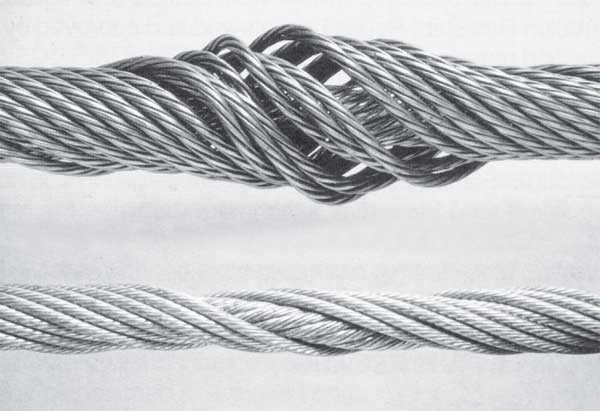
Kinks from the improper installation of new rope, the sudden release of a load or knots made to shorten a rope. A kink cannot be removed without creating a weak section. Discarding kinked rope is best.
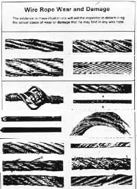
The following is a fairly comprehensive listing of critical inspection factors. It is not, however, presented as a substitute for an experienced inspector. It is rather a user’s guide to the accepted standards by which wire ropes must be judged. Use the outline to skip to specific sections:
Rope abrades when it moves through an abrasive medium or over drums and sheaves. Most standards require that rope is to be removed if the outer wire wear exceeds 1/3 of the original outer wire diameter. This is not easy to determine, and discovery relies upon the experience gained by the inspector in measuring wire diameters of discarded ropes.
All ropes will stretch when loads are initially applied. As a rope degrades from wear, fatigue, etc. (excluding accidental damage), continued application of a load of constant magnitude will produce incorrect varying amounts of rope stretch.
Initial stretch, during the early (beginning) period of rope service, caused by the rope adjustments to operating conditions (constructional stretch).
Following break-in, there is a long period—the greatest part of the rope’s service life—during which a slight increase in stretch takes place over an extended time. This results from normal wear, fatigue, etc.
Thereafter, the stretch occurs at a quicker rate. This means that the rope has reached the point of rapid degradation: a result of prolonged subjection to abrasive wear, fatigue, etc. This second upturn of the curve is a warning indicating that the rope should soon be removed.
In the past, whether or not a rope was allowed to remain in service depended to a great extent on the rope’s diameter at the time of inspection. Currently, this practice has undergone significant modification.
Previously, a decrease in the rope’s diameter was compared with published standards of minimum diameters. The amount of change in diameter is, of course, useful in assessing a rope’s condition. But, comparing this figure with a fixed set of values can be misleading.
As a matter of fact, all ropes will show a significant reduction in diameter when a load is applied. Therefore, a rope manufactured close to its nominal size may, when it is subjected to loading, be reduced to a smaller diameter than that stipulated in the minimum diameter table. Yet under these circumstances, the rope would be declared unsafe although it may, in actuality, be safe.
As an example of the possible error at the other extreme, we can take the case of a rope manufactured near the upper limits of allowable size. If the diameter has reached a reduction to nominal or slightly below that, the tables would show this rope to be safe. But it should, perhaps, be removed.
Today, evaluations of the rope diameter are first predicated on a comparison of the original diameter—when new and subjected to a known load—with the current reading under like circumstances. Periodically, throughout the life of the rope, the actual diameter should be recorded when the rope is under equivalent loading and in the same operating section. This procedure, if followed carefully, reveals a common rope characteristic: after an initial reduction, the diameter soon stabilizes. Later, there will be a continuous, albeit small, decrease in diameter throughout its life.
Deciding whether or not a rope is safe is not always a simple matter. A number of different but interrelated conditions must be evaluated. It would be dangerously unwise for an inspector to declare a rope safe for continued service simply because its diameter had not reached the minimum arbitrarily established in a table if, at the same time, other observations lead to an opposite conclusion.
Corrosion, while difficult to evaluate, is a more serious cause of degradation than abrasion. Usually, it signifies a lack of lubrication. Corrosion will often occur internally before there is any visible external evidence on the rope surface.
Pitting of wires is a cause for immediate rope removal. Not only does it attack the metal wires, but it also prevents the rope’s component parts from moving smoothly as it is flexed. Usually, a slight discoloration because of rusting merely indicates a need for lubrication.
Severe rusting, on the other hand, leads to premature fatigue failures in the wires necessitating the rope’s immediate removal from service. When a rope shows more than one wire failure adjacent to a terminal fitting, it should be removed immediately. To retard corrosive deterioration, the rope should be kept well lubricated with a clear wire rope lube that can penetrate between strands. In situations where extreme corrosive action can occur, it may be necessary to use galvanized wire rope.
Kinks are tightened loops with permanent strand distortion that result from improper handling when a rope is being installed or while in service. A kink happens when a loop is permitted to form and then is pulled down tight, causing permanent distortion of the strands. The damage is irreparable and the sling must be taken out of service.
Doglegs are permanent bends caused by improper use or handling. If the dogleg is severe, the sling must be removed from service. If the dogleg is minor, exhibiting no strand distortion and cannot be observed when the sling is under tension, the area of the minor dogleg should be marked for observation and the sling can remain in service.
Bird caging results from torsional imbalance that comes about because of mistreatment, such as sudden stops, the rope being pulled through tight sheaves, or wound on too small a drum. This is cause for rope replacement unless the affected section can be removed.
Particular attention must be paid to wear at the equalizing sheaves. During normal operations, this wear is not visible. Excessive vibration or whip can cause abrasion and/or fatigue. Drum cross-over and flange point areas must be carefully evaluated. All end fittings, including splices, should be examined for worn or broken wires, loose or damaged strands, cracked fittings, worn or distorted thimbles and tucks of strands.
After a fire or the presence of elevated temperatures, there may be metal discoloration or an apparent loss of internal lubrication. Fiber core ropes are particularly vulnerable. Under these circumstances the rope should be replaced.
Continuous pounding is one of the causes of peening. This can happen when the rope strikes against an object, such as some structural part of the machine, or it beats against a roller or it hits itself. Often, this can be avoided by placing protectors between the rope and the object it is striking.
Another common cause of peening is continuous working-under high loads—over a sheave or drum. Where peening action cannot be controlled, it is necessary to have more frequent inspections and to be ready for earlier rope replacement.
Below are plain views and cross-sections show effects of abrasion and peening on wire rope. Note that a crack has formed as a result of heavy peening.
Scrubbing refers to the displacement of wires and strands as a result of rubbing against itself or another object. This, in turn, causes wear and displacement of wires and strands along one side of the rope. Corrective measures should be taken as soon as this condition is observed.
Wires that break with square ends and show little surface wear have usually failed as a result of fatigue. Such fractures can occur on the crown of the strands or in the valleys between the strands where adjacent strand contact exists. In almost all cases, these failures are related to bending stresses or vibration.
If diameter of the sheaves, rollers or drum cannot be increased, a more flexible rope should be used. But, if the rope in use is already of maximum flexibility, the only remaining course that will help prolong its service life is to move the rope through the system by cutting off the dead end. By moving the rope through the system, the fatigued sections are moved to less fatiguing areas of the reeving.
The number of broken wires on the outside of a wire rope are an index of its general condition, and whether or not it must be considered for replacement. Frequent inspection will help determine the elapsed time between breaks. Ropes should be replaced as soon as the wire breakage reaches the numbers given in the chart below. Such action must be taken without regard to the type of fracture.
* All ropes in the above applications—one outer wire broken at the point of contact with the core that has worked its way out of the rope structure and protrudes or loops out of the rope structure. Additional inspection of this section is required.
Rope that has either been in contact with a live power line or been used as “ground” in an electric welding circuit, will have wires that are fused, discolored and/or annealed and must be removed.
On occasion, a single wire will break shortly after installation. However, if no other wires break at that time, there is no need for concern. On the other hand, should more wires break, the cause should be carefully investigated.
On any application, valley breaks—where the wire fractures between strands—should be given serious attention. When two or more such fractures are found, the rope should be replaced immediately. (Note, however, that no valley breaks are permitted in elevator ropes.)
It is good to remember that once broken wires appear—in a rope operating under normal conditions—a good many more will show up within a relatively short period. Attempting to squeeze the last measure of service from a rope beyond the allowable number of broken wires (refer to table on the next page) will create an intolerably hazardous situation.
Recommended retirement criteria for all Rotation Resistant Ropes are 2 broken wires in 6 rope diameters or 4 broken wires in 30 rope diameters (i.e. 6 rope diameters for a 1″ diameter rope = 6″).
Distortion of Rotation Resistant Ropes, as shown below, can be caused by shock load / sudden load release and/or induced torque, and is the reason for immediate removal from service.
Original equipment wire rope and replacement wire rope must be selected and installed in accordance with the requirements of this section. Selection of replacement wire rope must be in accordance with the recommendations of the wire rope manufacturer, the equipment manufacturer, or a qualified person.
Wire rope design criteria: Wire rope (other than rotation resistant rope) must comply with either Option (1) or Option (2) of this section, as follows:
Option (1). Wire rope must comply with section 5-1.7.1 of ASME B30.5-2004 (incorporated by reference, see § 1926.6) except that section"s paragraph (c) must not apply.
Option (2). Wire rope must be designed to have, in relation to the equipment"s rated capacity, a sufficient minimum breaking force and design factor so that compliance with the applicable inspection provisions in § 1926.1413 will be an effective means of preventing sudden rope failure.
Type I rotation resistant wire rope ("Type I"). Type I rotation resistant rope is stranded rope constructed to have little or no tendency to rotate or, if guided, transmits little or no torque. It has at least 15 outer strands and comprises an assembly of at least three layers of strands laid helically over a center in two operations. The direction of lay of the outer strands is opposite to that of the underlying layer.
Type II rotation resistant wire rope ("Type II"). Type II rotation resistant rope is stranded rope constructed to have significant resistance to rotation. It has at least 10 outer strands and comprises an assembly of two or more layers of strands laid helically over a center in two or three operations. The direction of lay of the outer strands is opposite to that of the underlying layer.
Type III rotation resistant wire rope ("Type III"). Type III rotation resistant rope is stranded rope constructed to have limited resistance to rotation. It has no more than nine outer strands, and comprises an assembly of two layers of strands laid helically over a center in two operations. The direction of lay of the outer strands is opposite to that of the underlying layer.
Type I must have an operating design factor of no less than 5, except where the wire rope manufacturer and the equipment manufacturer approves the design factor, in writing.
A qualified person must inspect the rope in accordance with § 1926.1413(a). The rope must be used only if the qualified person determines that there are no deficiencies constituting a hazard. In making this determination, more than one broken wire in any one rope lay must be considered a hazard.
Each lift made under § 1926.1414(e)(3) must be recorded in the monthly and annual inspection documents. Such prior uses must be considered by the qualified person in determining whether to use the rope again.
Rotation resistant ropes may be used as boom hoist reeving when load hoists are used as boom hoists for attachments such as luffing attachments or boom and mast attachment systems. Under these conditions, all of the following requirements must be met:
The requirements in ASME B30.5-2004 sections 5-1.3.2(a), (a)(2) through (a)(4), (b) and (d) (incorporated by reference, see § 1926.6) except that the minimum pitch diameter for sheaves used in multiple rope reeving is 18 times the nominal diameter of the rope used (instead of the value of 16 specified in section 5-1.3.2(d)).
The operating design factor for these ropes must be the total minimum breaking force of all parts of rope in the system divided by the load imposed on the rope system when supporting the static weights of the structure and the load within the equipment"s rated capacity.
Wire rope clips used in conjunction with wedge sockets must be attached to the unloaded dead end of the rope only, except that the use of devices specifically designed for dead-ending rope in a wedge socket is permitted.
Prior to cutting a wire rope, seizings must be placed on each side of the point to be cut. The length and number of seizings must be in accordance with the wire rope manufacturer"s instructions.
The purpose of this safety policy and procedure is to establish the methods and guidelines for the safe use of slings throughout [COMPANY]. Slings, a component of hoisting and rigging systems, are used to lift and move loads. In [COMPANY], alloy steel chain, wire rope, natural and synthetic fiber rope, and synthetic web slings are typically used. Slings are capable of lifting tremendous loads.
It is the policy of [COMPANY] is to provide a place of employment free from recognized hazards that cause or are likely to cause death or serious physical harm to employees or the public. Therefore, to minimize and eliminate material lifting hazards, properly rated slings that are not damaged or defective will be used in [COMPANY]. When hazards exist that cannot be eliminated, then engineering practices, administrative practices, safe work practices, Personal Protective Equipment (PPE), and proper training regarding Slings will be implemented. These measures will be implemented to minimize those hazards to ensure the safety of employees and the public.
The user should determine that the sling is being used in accordance with rated capacity as listed in the manufacturer’s catalog. The alloy steel chain, wire rope and fiber rope slings are typically used where sling damage to the load is not critical. Synthetic web slings are ideal where sling damage to a load is not acceptable.
Wire rope slings must be proof-tested by the manufacturer to ensure quality. A certificate verifying rated capacity will accompany each wire rope sling. This certificate must be available for review.
• In manila rope, eye splices will consist of at least three full tucks, and short splices will consist of at least six full tucks, three on each side of the splice center line.
• In synthetic rope, eye splices will consist of at least four full tucks, and short splices will consist of at least eight full tucks, four on each side of the center line.
• Strand end tails will not be trimmed flush with the surface of the rope immediately adjacent to the full tucks. This applies to all types of fiber rope and both eye and short splices. For fiber rope under one inch in diameter, the tail will project at least six inches beyond the last full tuck.
The following information is to be used as a guide for inspecting wire rope and wire rope slings. Inspection frequency should be based on safety factors, property damage, and the cost of replacing destroyed or damaged goods and material dropped due to the use or misuse of improper or damaged wire rope and slings. Additionally, slings should be inspected at regular intervals. This interval should be determined by the user and is dependent upon the particular use of the sling and [COMPANY] safety requirements. A sling should be inspected after any unusual situation that may have damaged it, such as overload, accident, or fire. It should not be returned in service until continued safe operation has been verified.Each sling should have a serial number. If no number is available, a tag should be attached at the time of inspection. This number should be listed on the inspection report. Inspection should be performed only by persons with sufficient experience and knowledge to properly apply the criteria for rejection. The following should be considered criteria for rejection:
• Abrasion: There should be no wearing, scrubbing, or preening of any outside wire causing the reduction of the diameter of a single wire by more than 1/3.
• Reduced Diameter: There should not be any reduction of the diameter of the rope along the main length or of any section (overloading or contact with sharp edges of load without permission).

All wire ropes will wear out eventually and gradually lose work capability throughout their service life. That"s why periodic inspections are critical. Applicable industry standards such as ASME B30.2 for overhead and gantry cranes or federal regulations such as OSHA refer to specific inspection criteria for varied applications.
You should thoroughly inspect all wire ropes at regular intervals. The longer it has been in service or, the more severe the service, the more thoroughly and frequently it should be inspected. Be sure to maintain records of each inspection.
Inspections should be carried out by a person who has learned through specialized training or practical experience of what to look for and who knows how to judge the importance of any abnormal conditions they may discover. It is the inspector"s responsibility to obtain and follow the proper inspection criteria for each application inspected.
Figure 1is what happens when a wire breaks under tensile load exceeding its strength. It"s typically recognized by the "cup and cone" appearance at the point of failure. The necking down of the wire at the point of failure to form the cup and cone indicates failure has occurred while the wire retained its ductility (the ability to change form without breaking).
Figure 2is a wire with a clear fatigue break. It is identified by the square end perpendicular to the wire. This break was produced by a torsion machine that"s used to measure the ductility. This break is similar to wire failures in the field caused by fatigue.
Figure 3 is a wire rope that has been subjected to repeated bending over sheaves under typical loads. This fatigue results in breaks in individual wires - these breaks are square and usually in the crown of the strands.
Figure 4 is an example of fatigue failure of a wire rope subjected to heavy loads over small sheaves. The breaks in the valleys of the strands are caused by "strand nicking." There may be crown breaks, too.
Figure 5 is a single strand removed from a wire rope subjected to "strand nicking." This condition is a result of adjacent strands rubbing against one another. While this is normal in a rope"s operation, the nicking can be accentuated by high loads, small sheaves or loss of core support. The ultimate result will be individual wire breaks in the valleys of the strands.

A new OSHA Safety and Health Information Bulletin (SHIB) advises employers on working safely with wire rope. Recent OSHA investigations found several workplace incidents, many involving fatalities, were connected to wire rope failures.
To assist employers in protecting workers from the hazards of rope wire failure, the new SHIB provides information on how wire rope is structured, what causes degradation, what to look for when inspecting ropes, and how often to inspect them.
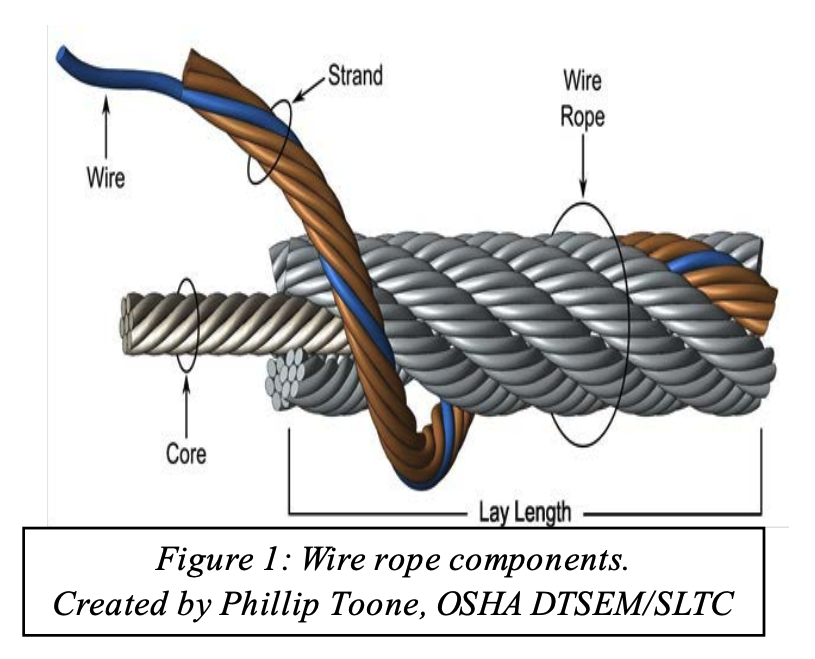
According to OSHA, wire ropes used for hoisting, lowering, and horizontally moving suspended loads are subject to high tensile stress and degradation through wear and corrosion. Wire ropes are made up of multiple strands of concentrically wound wire; the degradation of even one strand may result in an unexpected break of that strand and a sudden release in rope tension. This loss of tension may cause the load the rope is holding or the machine it is controlling to fall or move, putting workers at risk for crushing and struck-by injuries.
OSHA says that all wire rope components degrade over time in service but the degradation rate depends on several variables. The degradation rate can depend on such variables as:How often the load limit is exceeded;
The SHIB also includes a case study of a fatality that took place after a crane’s boom hoist wire rope failed, dropping the boom and load onto workers. The accident occurred in 2013 in Utah. OSHA"s Directorate of Technical Support and Emergency Management"s Salt Lake Technical Center analyzed rope samples from the section that failed and determined that most of the wires in the rope were already broken from fatigue before the incident occurred.
OSHA concluded that six years of loading and bending likely made the individual wires in the rope more brittle (i.e., metallurgical work hardening) before fatigue and tensile failure occurred. Numerous brittle wires in the rope broke over time and the remaining wires were unable to carry the load failure. Inspectors said that roper rope inspection and maintenance could have prevented the loss of these workers" lives.
General industry and construction standards that apply to wire rope inspection include the following in 29 CFR:1926.251, Rigging equipment for material handling


 8613371530291