
wire rope fleet angle quotation

The achievement of even winding on a smooth faced drum is closely related to the magnitude of the D/d ratio, the speed of rotation, load on the rope, and the fleet angle. Of all these factors, the one that exerts perhaps the greatest influence on winding characteristics is the fleet angle.
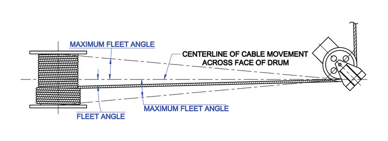
The schematic drawing (Fig. 39) shows an installation where the wire rope runs from a fixed sheave, over a floating sheave, and then on to the surface of a smooth drum. The fleet angle (Fig. 39) may be defined as the included angle between two lines; one line drawn through the middle of the fixed sheave and the drum – and perpendicular to the axis of the drum and a second line drawn from the flange of the drum to the base of the groove in the sheave. (The drum flange represents the farthest position to which the rope can travel across the drum.) There are left and right fleet angles, measured to the left or right of the center line of the sheave, respectively.
It is necessary to restrict the fleet angle on installations where wire rope passes over the lead or fixed sheave and onto a drum. For optimum efficiency and service characteristics, the angle here should not exceed 1 1/2º for a smooth drum, or 2º for a grooved drum. Fleet angles larger than these suggested limits can cause such problems as bad winding on smooth drums, and the rope rubbing against the flanges of the sheave grooves. Larger angles also create situations where there is excessive crushing and abrasion of the rope on the drum. Conversely, small fleet angles – less than 1/2º – should also be avoided since too small an angle will cause the rope to pile up.

This one is about Fleet Angles on Wire Rope. An important topic in any wire rope reeving system, this article looks at fleet angles both at the drum and at the sheave.
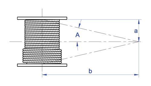
Fleet Angle is usually defined as the included angle between two lines, one which extends from a fixed sheave to the flange of a drum and the other which extends from the same fixed sheave to the drum in a line perpendicular to the axis of the drum.
When spooling wire rope onto a smooth/plain drum it is generally recommended that the fleet angle is limited to between 0.5 and 2 degrees. If the fleet angle is too small, ie less than 0.5 degrees, the rope will tend to pile up at the drum flange and fail to return across the drum. In this situation, the problem may be alleviated by increasing the fleet angle through the introduction of a sheave or spooling mechanism.
If the rope is allowed to pile up it will eventually roll away from the flange, creating a shock load in both the rope and the drum assembly, thus creating an undesirable and unsafe operating condition.
Excessively high fleet angles will return the rope across the drum prematurely, creating gaps between wraps of rope close to the flanges as well as increasing the pressure on the rope at the cross-over positions.
Where drum grooving is provided, large fleet angles will result in wear taking place to the drum grooving which may then result in the rope miss-spooling on the drum. When spooling onto a grooved drum, it is recommended that the fleet angle is limited to between 0.5 and 4 degrees for 6&8 stranded single layer construction wire ropes and between 0.5 and 2 degrees for rotational resistant and parallel laid construction wire ropes. Note, for high speed spooling of wire rope in excess of 8m per second it may be necessary to reduce the fleet angle to 0.5 to 1.5 degrees especially at high D/d ratios.
Level winding/spooling mechanisms can be positioned in front of a wire rope winch drum to guide the rope across the face of the drum to provide superior spooling utilising fleet angles between 0.25 and 1.5 degrees
When a fleet angle exists as the rope enters a sheave, it initially makes contact with the sheave flange. As the rope continues to pass through and around the sheave it moves down the flange until it sits in the bottom of the groove. In doing so, even when under tension, the rope will actually roll as well as slide. As a result of the rolling action the rope is twisted where turn is induced into or out of the rope. This either shortens or lengthens the lay length of the outer strands which can damage the rope and cause ‘birdcages’ or similar distortions within the rope. A s the fleet angel increases so does the amount of twist
The fleet angle within the reeving system should be limited to 4 degrees for 6 & 8 stranded single layer construction wire ropes and 2 degrees for rotational resistant and parallel laid construction wire ropes. It is recognised that it is not always possible to comply with these general recommendations. This may be the case in applications such as overhead hoists. In which case the rope life can be affected.
Please do not hesitate to contact the team at Crane Ropes Australia or give us a call at LiftQuip on 7089 8335 if you would like more clarification or would like to work through some technical issues you may be having with your wire rope.

Using a winch to lift or position a load gives your project flexibility because you can have this material handling muscle positioned in various ways. You can place the winch above the load and use it vertically as a hoist, or have it on the same level of the load to pull horizontally, or use pulleys with it so you can position the winch where you want it and move the load in the direction(s) that you need it to go. But when you are determining where to position your winch, it is important that you consider the critical distance needed to maintain the necessary fleet angle to keep things safer and in proper working order.
What is fleet angle? Fleet angle is the angle between the wire rope and an imaginary line extending perpendicular to the drum. This angle varies with the width of the drum and the distance between the lead sheave and the drum. The proper fleet angle helps the wire rope to wind evenly onto the drum, and helps to reduce wear to the wire rope, drum, and lead sheave. Too large a fleet angle will cause the wire rope to wind loosely, overlap and possibly jump the flange and cause severe damage to the equipment. That’s why it’s important to properly distance the winch from the lead sheave (also sometimes called fixed sheave) when you are determining where to position your winch. A maximum fleet angle of 1-1/2° for smooth drums, and 2° for grooved drums, helps the wire rope wind uniformly. A narrower drum can also help stay within the recommended fleet angle if the critical fleet angle distance can’t be improved. Diagrams below are examples of common rigging layouts that show where critical fleet angle distances are to be measured so you can stay within the proper maximum fleet angle.
So next time you want to take advantage of the benefits of using a winch to move or position a load, make sure you are practicing proper distancing…fleet angle distancing.

In this article, we outline important technical topics related to wire rope. This information has been sourced from and approved by Bridon American. Use the outline to skip to specific sections:
Any assembly of steel wires spun into a helical formation, either as a strand or wire rope (when subjected to a tensile load) can extend in three separate phases, depending on the magnitude of the applied load.
At the commencement of loading a new rope, extension is created by the bedding down of the assembled wires with a corresponding reduction in overall diameter. This reduction in diameter is accommodated by a lengthening of the helical lay. When sufficiently large bearing areas have been generated on adjacent wires to withstand the circumferential compressive loads, this mechanically created extension ceases and the extension in Phase 2 commences. The Initial Extension of any rope cannot be accurately determined by calculation and has no elastic properties.
The practical value of this characteristic depends upon many factors, the most important being the type and construction of rope, the range of loads and the number and frequency of the cycles of operation. It is not possible to quote exact values for the various constructions of rope in use, but the following approximate values may be employed to give reasonably accurate results.
Following Phase 1, the rope extends in a manner which complies approximately with Hookes Law (stress is proportional to strain) until the limit of proportionality or elastic limit is reached.
It is important to note that wire ropes do not possess a well defined Young’s Modulus of Elasticity, but an ‘apparent’ Modulus of Elasticity can be determined between two fixed loads.
By using the values given, it is possible to make a reasonable estimate of elastic extension, but if greater accuracy is required, it is advisable to carry out a modulus test on an actual sample of the rope. As rope users will find it difficult to calculate the actual metallic steel area, the values can be found in the Wire Rope Users Manual or obtained from Bridon Engineering.
The permanent, non-elastic extension of the steel caused by tensile loads exceeding the yield point of the material. If the load exceeds the Limit of Proportionality, the rate of extension will accelerate as the load is increased until a loading is reached at which continuous extension will commence, causing the wire rope to fracture without any further increase of load.
The coefficient of linear expansion (∝) of steel wire rope is (6.94 x 10⁻⁶ per °F) and therefore the change in length of 1 foot of rope produced by a temperature change of t (°F) would be:
Example: What will be the total elongation of a 200 ft. length of 1-1/8″ diameter Blue Strand 6 x 41 IWRC wire rope at a tension of 20,000 Ibs. and with an increase in temperature of 20°F?
In addition to bending stresses experienced by wire ropes operating over sheaves or pulleys, ropes are also subjected to radial pressure as they make contact with the sheave. This pressure sets up shearing stresses in the wires, distorts the rope’s structure and affects the rate of wear of the sheave grooves. When a rope passes over a sheave, the load on the sheave bearing results from the tension in the rope and the angle of rope contact. It is independent of the diameter of the sheave.
Assuming that the rope is supported in a well fitting groove, then the pressure between the rope and the groove is dependent upon the rope tension and diameter, but is independent of the arc of contact.
It must be realized that this method of estimation of pressure assumes that the area of contact of the rope in the groove is on the full rope diameter, whereas in fact only the crowns of the outer wires are actually in contact with the groove. It is estimated that the local pressures at these contact points may be as high as five times those calculated. If the pressure is high, the compressive strength of the material in the groove may be insufficient to prevent excessive wear and indentation, and this in turn will damage the outer wires of the rope and effect its working life.
As with bending stresses, stresses due to radial pressure increase as the diameter of the sheave decreases. Although high bending stresses generally call for the use of flexible rope constructions having relatively small diameter outer wires, these have less ability to withstand heavy pressures than do the larger wires in the less flexible constructions. If the calculated pressures are too high for the particular material chosen for the sheaves or drums or indentations are being experienced, consideration should be given to an increase in sheave or drum diameter. Such a modification would not only reduce the groove pressure, but would also improve the fatigue life of the rope.
The pressure of the rope against the sheave also causes distortion and flattening of the rope structure. This can be controlled by using sheaves with the correct groove profile, which, for general purposes, suggests a recommended groove diameter of nominal rope diameter +6%. The profile at the bottom of the groove should be circular over an angle of approximately 120° and the angle of flare between the sides of the sheave should be approximately 52°.
Bend fatigue testing of ropes usually consists of cycling a length of rope over a sheave while the rope is under a constant tension. As part of their ongoing development program, Bridon has tested literally thousands of ropes in this manner over the years on their own in-house design bend testing equipment.
Through this work, Bridon has been able to compare the effects of rope construction, tensile strength, lay direction, sheave size, groove profile and tensile loading on bend fatigue performance under ideal operating conditions. At the same time it has been possible to compare rope life to discard criteria (e.g. as laid down in ISO 4309) with that to complete failure of the rope, i.e. to the point where the rope has been unable to sustain the load any longer. As part of the exercise, it has also been possible to establish the residual breaking strength of the rope at discard level of deterioration.
What needs to be recognized, however, is that very few ropes operate under these controlled operating conditions, making it very difficult to use this base information when attempting to predict rope life under other conditions. Other influencing factors, such as dynamic loading, differential loads in the cycle, fleet angle, reeving arrangement, type of spooling on the drum, change in rope direction, sheave alignment, sheave size and groove profile, can have an equally dramatic effect on rope performance.
If designers or operators of equipment are seeking optimum rope performance or regard bending fatigue life as a key factor in the operation of equipment, such information can be provided by Bridon for guidance purposes.
Wire ropes are manufactured slightly larger than the nominal diameter. The maximum allowable oversize tolerances provided by industry standards are shown in the following table:
Under certain circumstances it may be necessary to use a swivel in a lifting system to prevent rotation of the load. This is typically done for employee safety considerations. It is possible however, that the use of a swivel will have an adverse affect on rope performance and may, in some cases, damage the wire rope.
The type of swivel that causes the most concern from the standpoint of the wire rope is the independent anti-friction swivel that attaches directly to the rope. The purpose of using a swivel in a lifting system is to prevent rotation of the load. This then allows the wire rope to rotate. Excessive rope rotation can damage a wire rope.
To assist in determining whether or not a swivel should be used in the lifting system, the following recommendations should be considered. It must also be recognized that the rotation characteristics of different types and constructions of wire rope vary considerably. The following types and constructions of wire rope are grouped according to their rotation characteristics.
These rope constructions will rotate excessively with one end free to rotate, and the rope will unlay and distort and be easily damaged with a loss of rope breaking force.Blue Strand 6 x 19 and 6 x 36 Class Lang Lay
Wire rope constructions having high rotation characteristics when used in single part reeving may require a swivel in the system to prevent rotation in certain operating conditions. However, this should be done only when employee safety is the issue.
These rope constructions, when used in a reeving system with one end free to rotate, will have a high level of rotation. This will cause the rope to unlay and, to some degree, distortion of the rope will occur.Blue Strand 6 x 19 and 6 x 36—Class Regular Lay
The ropes in this Group are designed with an inner rope that is laid in the opposite direction to the outer strands to provide a medium resistance to rotation. Ropes with medium rotation characteristics are used with a swivel in single part reeving applications. However, a swivel is not recommended for multiple part hoisting applications or in any application where the swivel is not necessary for safety reasons. If it is necessary to use a swivel, the rope must be operating at a design factor of 5 or greater, must not be shock loaded and must be inspected daily by a qualified person for distortion.
It should be noted that if a swivel is used on conjunction with Group 3a ropes, rope service life might be reduced due to increased internal wear between the outer strands and the inner rope.Group 3aEndurance 8RR Rotation Resistant
Wire ropes having low rotation characteristics used in either single or multiple part reeving may be used with a swivel. The reason for this is that the ropes will exhibit very little, if any, rotation when used at the proper design factor. Application parameters, such as a fleet angle, may induce turn into a wire rope that can be relieved by the use of a swivel. However, if the application does not induce any turn into the rope, or if a swivel is not beneficial to the performance of the rope, the swivel may not be necessary.Endurance 35 LS
Fleet angle is usually defined as the included angle between two lines: one which extends from a fixed sheave to the flange of a drum, and the other which extends from the same fixed sheave to the drum in a line perpendicular to the axis of the drum (see illustration).
If the drum incorporates helical grooving, the helix angle of the groove needs to be added or subtracted from the fleet angle as described above to determine the actual fleet angle experienced by the rope.
When spooling rope onto a drum, it is generally recommended that the fleet angle is limited to between 0.5° and 2.5°. If the fleet angle is too small, i.e. less than 0.5°, the rope will tend to pile up at the drum flange and fail to return across the drum. In this situation, the problem may be alleviated by introducing a ‘kicker’ device or by increasing the fleet angle through the introduction of a sheave or spooling mechanism.
If the rope is allowed to pile up, it will eventually roll away from the flange, creating a shock load in both the rope and the structure of the mechanism, an undesirable and unsafe operating condition.
Excessively high fleet angles will return the rope across the drum prematurely, creating gaps between wraps of rope close to the flanges, as well as increasing the pressure on the rope at the cross-over positions.
Even where helical grooving is provided, large fleet angles will inevitably result in localized areas of mechanical damage as the wires ‘pluck’ against each other. This is often referred to as ‘interference’, but the amount can be reduced by selecting a Langs lay rope if the reeving allows. The “interference” effect can also be reduced by employing a Dyform rope, which offers a much smoother exterior surface than conventional rope constructions.
Where a fleet angle exists as the rope enters a sheave, it initially makes contact with the sheave flange. As the rope continues to pass through the sheave it moves down the flange until it sits in the bottom of the groove. In doing so, even when under tension, the rope will actually roll, as well as slide. As a result of the rolling action, the rope is twisted, i.e. turn is induced into or out of the rope, either shortening or lengthening the lay length of the outer layer of strands. As the fleet angle increases, so does the amount of twist.
To reduce the amount of twist to an acceptable level, the fleet angle should be limited to 2.5° for grooved drums and 1.5° for plain drums and when using Rotation Resistant, ropes the fleet angle should be limited to 1.5°.
However, for some crane and hoist applications, it is recognized that for practical reasons. It is not always possible to comply with these general recommendations, in which case, the rope life could be affected.
The problem of torsional instability in crane hoist ropes would not exist if the ropes could be perfectly torque balanced under load. The torque generated in a wire rope under load is usually directly related to the applied load by a constant ‘torque factor’. For a given rope construction, the torque factor can be expressed as a proportion of the rope diameter and this has been done below.
Variation with rope construction is relatively small and hence the scope for dramatically changing the stability of a hoisting system is limited. Nevertheless, the choice of the correct rope can have a deciding influence, especially in systems which are operating close to the critical limit. It should be noted that the rope torque referred to here is purely that due to tensile loading. No account is taken of the possible residual torque due, for example, to rope manufacture or installation procedures.
Torsional Stability and the Cabling Graph are two methods which can be used to determine torsional stability or the tendency of the rope to cable. The torque factors quoted are approximate maximum values for the particular constructions. To calculate the torque value for a particular rope size, multiply by the nominal rope diameter.
The torsional characteristics of wire rope will have the effect of causing angular displacement of a sheave block when used in multi-fall reeving arrangements. The formula below gives a good approximation under such arrangements.
The preceding equations are all relative to a simple two part reeving. For more complex systems, a similar approach may be used if account is taken of the different spacings of the ropes.
The equations assume that rope is torque-free in the noload condition, therefore, induced torque during or immediately after installation will adversely influence the calculated effect.
The above data assumes a constant torque value which is a valid assumption for a new rope. Wear and usage can have a significant effect on the torque value, but practical work shows that under such circumstances, the torque value will diminish, thus improving the stability of the arrangement. Some arrangements may be of such complexity that the evaluation demands a computer study.
Assuming a pedestal crane working on two falls is roped with 20mm diameter DYFORM 34LR and the bottom block carries a sheave of 360mm diameter with the falls parallel:
If the rope is new (worst condition) and no account is taken of block weight and friction then angular displacement for a height of lift of 30 meters is given by:
Field research jointly conducted by the Wire Rope Technical Board and the Power Crane and Shovel Association has shown that cabling of the rope parts in a multiple part reeved hoisting arrangement is controlled by several factors. The following calculations and graphs can be used to determine when and if cabling will occur on multiple part reeved hoisting arrangements.
Various constructions of rope shown on the graph indicate the limited conditions for torsional stability with the angular displacement of the hoist block to a maximum of 90 degrees. When the operating conditions for a particular installation give a resultant above the appropriate band, then cabling of the falls will most likely occur. If the operating conditions give a resultant below any particular band, the cabling of the falls will most likely not occur. If the operating conditions for any particular installation fall within the band, cabling is unpredictable.
An importantpoint to consider is the selection of the proper type of core needed in the rope. Wire Ropes are made with either fiber core or steel wire core.
This center is usually composed of a separate 7×7 wire rope designated as IWRC. The steel core increases the strength by 7% and the weight by 10%. These steel cores provide more substantial support than fiber cores to the outer strands during the rope’s operating life. Steel centers resist crushing, are more resistant to heat and increase the strength of the rope.
The Design Factor being both the ratio between the minimum Breaking load of the rope and the rated capacity (RC) tells at what percentage of its ultimate strength a wire rope is operating. The Design Factor takes into consideration both normal rope wear and potential stresses in various applications. The best practice in determining an adequate design factor is to analyze the specific conditions involved inn each individual installation. The following example shows how to determine the Design Factor: If a rope is working under a max. operating load of 10,000 lbs. and is having an ultimate strength of 50,000 lbs., the factor is 5 which means it is operating at 20% of its ultimate strength.
The fleet angle is the angle formed between the rope running to or from the extreme left or right of the drum and a line drawn from the center of the sheave normal to the axis of the drum. For optimum efficiency, the angle here should not exceed 1 1/2 degrees for a smooth drum, or 2 degrees for a grooved drum. If the fleet angle is larger than the recommended limits, it can cause bad winding on smooth drums and rubbing against the flanges of the grooves. Too small a fleet angle should also be avoided since it will cause the rope to pile up against the flange head.
Proper alignment of sheaves is essential. The main sheave should line up with the center of the hoisting drum, otherwise both the rope and sheave flanges will be subjected to severe and rapid deterioration will occur. If rope speeds are high, sheaves should also be balanced.
Wire rope products will break if abused, misused or overused. Regular inspection and maintenance are necessary. Consult industry recommendation and OSHA standards before using.
The fleet angle Ø, as displayed in FIGURE 2, governs the position of the lead sheave with respect to the drum. When the rope is at one end of the drum, against the drum flange, this fleet angle may not exceed one and a half degrees (1.5˚) for plain drums to two degrees (2˚) for grooved drums left or right from the centre line passing through the centre of the sheave groove and the midpoint of the drum.
Fleet angles larger than these suggested parameters can cause bad rope winding on drums and the rope can rub against the flanges of the sheave groove.

In order to insure proper wrapping on the drum and no undue wear of the wire rope, the fleet angle should be kept as small as practical. This is important to consider during the planning of a winch installation. Sheaves and drums should be placed so that the fleet angle will be equal on each side of the centerline of rope travel.
For a smooth drum a maximum fleet angle of 1-1/2 degrees is recommended. When the drum is grooved to suit the wire rope, the fleet angle should not exceed 2 degrees.

As a rule, the spooling angle should be between ¼° and 1 ¼°. At the same time, however, the design and speed of the cable must be taken into account. In borderline cases, please contact our specialists.

All Rights Reserved. Designated trademarks and brands are the property of their respective owners. Use of this Web site constitutes acceptance of the LeBus International, Inc. Privacy Policy Powered by Relidy.

This invention relates to drums and sheaves used to support wire rope in wire rope systems for lifting heavy loads, such as used in electric mining shovels and walking draglines.
It is important that wire rope be properly supported when it is wound up on a drum if it is not properly supported the wire rope will become mashed. This will result in the breaking of the wires in the central area of the wire rope. Breaking of the wires in the central area of the wire rope can lead to premature failure of the rope because it is not possible to visually inspect rope internal damage. This is an especially dangerous form of wire rope failure. When the wire rope is supported on a drum a spiral groove is placed in the outside periphery of the drum. In the prior art, the shape of the groove was in the form of a half radius of a circle. It was important for the height of the side of the groove to be sufficiently great in order to properly support the wire rope.
This invention provides a device adapted to support a wire rope of known nominal diameter in a system where the fleet angle of rope departure from the device is other than perpendicular to the device, the device comprising a cylindrical body, and a groove around the cylindrical body, the groove having a contour adapted to support the wire rope, the groove contour being such that the wire rope is adapted to be supported through a rope support angle somewhere between 100 degrees and 160 degrees, the rope support angle being the included angle from the nominal rope"s center to each end of the supporting groove contour on each side of the groove, the improvement comprising the groove contour being parabolic in shape over at least about the upper half of the groove contour.
This invention also provides such a device such that the improvement comprises the groove contour having a radial length from the nominal rope center to the contour greater than at the bottom of the groove over at least about the upper half of the groove contour.
This invention also provides a method of making such a device, the method comprising designing the groove contour such that as the wire rope leaves the groove there is a single line of contact between the rope and the respective side of the groove.
Figure 10 is a graphical view of the rope in the "YZ" plane Figure 11 is a plot of the solution to equation 3.30 Figure 12 is a plot of the solution to equation 3.31.
The surface mining industry utilizes large equipment to extract the Earth"s many raw materials: e.g. gold, copper, coal and phosphate. Electric mining shovels and walking draglines are the two main types of machines that are used to move or uncover these raw materials. Both of these types of excavating equipment utilize large quantities of large diameter wire rope.
The most common means of driving a rope to do work is through the use of a drum. One end of the wire rope is attached to the drum and then the drum is rotated which allows the rope to wind onto it. Drums on walking draglines are cylindrical in shape, have flanges on both ends and have a series of grooves for the rope to wind onto.
The grooves provide an excellent rope support which reduces the radial pressure and helps resist crushing, which improves rope life, when compared to an ungrooved wire rope drum. The grooves also provide a path for the rope to follow as it winds onto the drum. This keeps adjacent wraps on the drum from touching one another. The flanges on grooved drums are to provide structural support and may be used to attach the dead end of the wire rope or a bull gear which would provide the torque needed to rotate the drum.
The nomenclature of a generic drum assembly is shown in Figure 1. This illustration greatly exaggerates the rope pitch diameter, drum tread diameter and the rope diameter to better illustrate the groove angle and the rope pitch.
The hoisting drums on walking draglines are grooved and have only a single layer of rope wound onto it. Most of the drums have two ropes which are attached at the drum"s center. Each rope would then wind towards the flanges of the drum.
Drums on walking draglines are typically designed to the minimum recommended tread diameter to minimize the manufacturing and operating costs. Due to the enormous lengths of wire rope required to operate a Walking Dragline the length of the drum (i.e.
T"he sheaves on a Walking Dragline are very similar to a drum. They both have a rope that rides on them and have a groove contour to support the rope. The only real difference is that the sheave has no groove pitch. Figure 2 shows the nomenclature for a generic sheave. This nomenclature will be used throughout this thesis.
Wire rope is one of the most uniform and reliable mechanical products ever invented. If a wire rope is properly used and maintained it can provide an excellent service life. But, if a wire rope were to be abused in shipping, installation or during operation the service life of the rope can and probably will be much less than satisfactory.
Drum diameters are generally referenced as a ratio of the diameter of the sheave or drum (D) with respect to the diameter of the rope (d). This is the D/d ratio. Due to the limited deck space and the cost of manufacturing and operating a large drum on walking draglines and Electric mining shovels the drum D/d ratios are nearly always made to the recommended minimum value of 24.
When drums and sheaves are used in a system, the sheave diameters should be generally larger in diameter than the drum. This is due to the rope only being bent once at the drum and twice at the sheave for each direction of travel. When the rope travels over each sheave the rope will be bent to conform the radius of the sheave as it enters and then bent straight again as it exits the sheave. This is very important on walking draglines since the portion of wire rope operating at the drum may never operate at the boom point sheaves. If the fatigue accumulation is twice as great at the boom point as at the drum, the rope will fail prematurely at the boom point. This phenomenon is simply based on the design.
A fleet angle is the angle between the rope, as it leaves the drum and enters the head sheave, and the plane perpendicular to the axis of the drum. If the angle becomes too great the rope will touch "scrub" onto the groove of the drum or the adjacent wrap on the drum, or both. If a rope is scrubbing, there will be a visible thin band of worn material parallel to the axis of the rope and stretching a long distance along the rope.
This wear is often subject to high pressure, heat and abrasion. If the heat generated by scrubbing raises the local temperature beyond the steels critical temperature, martensite will form on the wires. Martensite is very brittle phase of steel. This will form surface cracks in the wires when the rope is bent around sheaves and drums. Eventually these cracks will propagate through the wire. If no heat is generated the outer wires will simply wear very thin and break.
Scrubbing is a purely geometrical concept. It is the wiping action of the rope onto another rope or the groove contour of the drum. Scrubbing is mainly caused by operating at too high of a fleet angle. Although, scrubbing is also dependent upon the system parameters such as groove contour, rope pitch, drum and rope diameters. When a drum is designed, manufactured and put into service, all of these parameters become fixed. The only geometric parameter that changes is the fleet angle. For every position on a drum there exists a unique fleet angle value.
Every rope which is wound onto a drum is subject to a fleet angle and a groove angle. The fleet angle is the angle the rope needs to follow in order to reach the head sheave as it is wound off a drum. The fleet angle changes for every position along the drum which is defined as the angle between the rope, as it leaves the drum and enters the head sheave, and the plane perpendicular to the axis of the drum. In the prior art, the groove angle, on the other hand, always remains the same for any position on the drum.
The groove angle, sometimes referred to as lead angle, equals the arc-tangent of the drums groove pitch divided by the circumference at the groove tread diameter.
Groove Angle = arcta~ Gr°°ve Pitch ~ Drum Tread Diameter 7z ( 1.1 ) The fleet angle plus the groove angle is called the total fleet angle. Figure shows a schematic of a sheave and drum system. The drum shown has a right hand lead and a left hand lead grooving with the typical 2 to 2.5 dead wraps (for normal safe operation) and the rest of the grooves are termed active grooves. As shown in Figure 5, the helix angle will either add to or subtract from the groove angle to form the total fleet angle. This is dependent on the direction of grooving. When the fleet angle is large and the drum groove pitch is large the head sheave may need to be shifted to either the right or the left in order to equalize the total fleet angle seen by the drum. If the fleet angles are large, the pitch of the grooves can be increased to eliminate "Rope to Rope"
Scrubbing can be a very serious and costly mode of rope failure. When a rope system experiences severe scrubbing, rope life on that machine will be a fraction of what is expected and the cost of altering the machine while its in operation can cost literally cost millions of dollars.
The "Roebling Wire Rope Handbook" derives a set of close form equations needed to predict the fleet angle at which rope scrubbing will occur based on known values: drum diameter, pitch of grooving and the diameter of wire rope. The following equation defines the total fleet angle that will just cause contact with the preceding wrap on the drum.
Y:= ~d2 - (X- h)2~~5 (1.3) X= h-2 2 Ch2 + 8 d2l (1.4) Where "h" equals the pitch of the grooving , "D" equals the tread diameter of the drum and "d" equals the diameter of the rope.
Using equation 1.2 we can easily find out what angle will cause scrubbing for any given position on the drum. What if we wanted to know what pitch diameter will cause scrubbing based on a known maximum fleet angle; such as 2.000°? With the use of a computer and some iterative math software a program can iterate through these equations and find the exact pitch required. To select a proper rope pitch, the program is used to find the pitch that will just induce scrubbing based on a certain fleet angle, drum and rope diameter. Then, when the rope is at its maximum material condition a small percentage of the ropes diameter is added to the pitch and a gap is defined.
Drum groove scrubbing is when the fleet angle of the rope leaving the drum would be great enough to cause interference between the actual drum profile and the rope; See Figure 3. When scrubbing occurs the outer strands are abrasively worn away in a thin band on only one side of the rope. Groove and rope scrubbing will appear to be the same on the damaged rope, but are caused by two completely different modes of generation.
Drum groove design has been virtually unchanged for many years. The drum groove contour has a specifically defined radius for each given rope diameter which is stated in "Wire Rope Handbook". The maximum allowable fleet angle of the rope is also said to be no greater than 1.50° for smooth drums and 2.00° for grooved drums. The Handbook does state however, that "Fleet angles larger than these suggested limits can cause such problems as ....... the rope rubbing against the flanges of the sheave grooves."
to No reference has been found which gives any indication as to what values design parameters like drum diameter, rope diameter, fleet angle, groove lead and groove radius should have to reduce or eliminate drum groove scrubbing. Now that CNC
machining and computer technologies has evolved so rapidly, the possibility of optimizing the groove contour and pitch to eliminate both "Rope to Rope" and "Rope to Drum"
The initial concept for formulating the governing equations was that, if the rope were to touch the groove, in three dimensional space, then a common point, or set of points, will exist between the rope and the groove. If there are many points, chances are they will form one or more three dimensional continuos curves. When the rope and the groove touch at one point it will be defined as having the coordinates <"Xend","Yend","Zend">.
The next step is to define the equation of the helical rope groove contour as a function of its governing variables in each of the three Cartesian coordinate directions.
Then the equations in the "X", "Y", "Z" directions are defined as being equal to "Xend", "Yend", "Zend" respectively. This equation definition can also be done for the ropes surface. If a point on the rope is to be common to a point on the groove, in order for scrubbing to occur, then the "Xenc~" of the rope is equal to the "Xend" of the groove. This coordinate equalization will be the basis for formulating all the governing relationships.
A single point on the groove contour is then geometrically described. This point is then swept out in the form of a helix in order to simulate the drum groove pitch. This will then define the helix in the "X", "Y" and "Z" directions. Three Cartesian equations a for the rope surface will then be defined. Extensive variable substitution and elimination then yields one equation in two unknowns. Lastly, the final equation is optimized in order to find the absolute minimum value for the drum radius, "Helix Z", that will cause "Rope to Drum" scrubbing to occur.
The governing equation derivation was broken into two main parts. The first part was to symbolically define the groove profile on the drum and the second part was to symbolically define the surface of rope as it leaves the drum. Both of these parts were defined in three dimensional space using the Cartesian coordinate system as a set of closed form equations.
After this set of equations was defined, a step by step variable substitution and elimination was performed. These equations were then reduced to one equation and two unknowns (a height "Helix Z" and an angle).
The last step was to set the equation equal to zero and solve for the variable that is quadratic in nature (a height "Helix Z"). This resulted in one equation with one unknown (an angle "A"). The minimum value of this equation defines the exact angle at which scrubbing will first occur.
1 6 Pitch - h,~ j=x X = Xend (3.1) The distance "Xend" propagates along the drum axis and is directly proportional to the "helix angle". "Xend" is defined as the final solution point in the "X" direction.
The final solution will be where the rope and the groove will just start to intersect. This is where scrubbing will just start to occur. In 360° of rotation, the distance traveled along the drum axis is equal to the pitch of the groove. The "Helix X" term is an arbitrary axial offset in the negative "X" direction. Later on this value will be a predetermined incremental step which will be used to generate the "Ideal Groove Contour".
by simply changing the Sine and Cosine values of the helix roll angle. From a mathematical point of view this relationship will form redundant equations in the "Y" and "Z" directions. For this reason, only the equations in the "Z" and "X"
directions will be required. The loss of one degree of freedom will be compensated for by introducing the general equation of an ellipse. When defining the equations for the rope, an ellipse is created when the cylindrical wire rope is cut with a plane at the fleet angle.
Helix Z cos(8) = Zend (3.2) The same point used in equation 3.1 was also used as the starting point on the groove profile for equation 3.2. The height of "Helix Z" is directly proportional to the cosine of the helix angle ("8"). The "Zend" term will be defined as the final solution in the "Z" direction. Figure 7 shows how "Helix X" relates to "Helix Z". For any value of "Helix X" there exists a "Helix Z" value, such that scrubbing on the drum will initially start. Our goal will be to derive an equation that equates the radial height, "Helix Z", directly to all known quantities.
First, assume that the rope fleets off of the drum in a straight line, it is centered within the drum"s radius and that the rope returns to a cylindrical shape very shortly after leaving the drums surface. The global coordinate axis will be centered on the axis of the drum with the centerline of the rope passing through the "Z" axis and the axis of the rope running directly down the "Y" axis while at a zero degree fleet angle. This is the same global position as stated above.
The fleet angle is the angle at which the rope leaves the drum. This fleet angle is zero only at when the rope leaves the drum exactly perpendicular to the "X Z"
plane. As the rope winds onto the drum the fleet angle will either increase of decrease depending on the position of the head sheave. For a single layer hoisting drum, the maximum fleet angle usually occurs when the drum is completely full. This is when the rope has wound onto the last and final wrap available on the drum. For our analysis, a random position on the drum was chosen to be the global axis system. The "~" axis of this system passes through the center of the groove and the rope. The fleet angle will be positive when the rope rotates about the positive "Z" axis. Figure 8 shows the basic geometry of a rope as it leaves the drum when subjected to a fleet angle.
Figure 9 shows how the cutting plane creates an ellipse as it intersects the rope at a fleet angle. Remember, the axis of the rope only rotates about the "Z" axis and remains in a plane parallel to the "X Y" plane. Figure 10 shows a view looking in the "YZ" plane which shows the relationship of the helical roll angle, "Yend", and the solution point "P"
The first step is to define the relationship between the center of the ellipse and the fleet angle as equation 3.3. To better see where this relationship comes from, view Figures 3.2-3, 3.2-4 and 3.2-5 all at the same time.
direction is the distance to the center of the ellipse minus the distance back to the contour of the ellipse at the solution point "P". This is simply one half the drum rope pitch diameter "DRPD" minus the "Y Ellipse". This is shown below as equation 3.8.
.5 1 DRPD - 1 - x rl 2 - Zend 2 r2 2 (3.13) Equations 3.9, 3.11 and 3.13 are the three final equations which define the final solution on the surface of the rope. The next step is to define the values for "rl" and "r2". The quantity "rl" is the minor axis of the ellipse, which is defined as the drum rope radius "DRR" since the axis of the rope is parallel to the "X Y" plane.
rl = DRR (3.14) The quantity "r2" is the major axis of the ellipse which is defined as the drum rope radius divided by the Cosine of the fleet angle "a". The "intersecting plane" cuts the cylindrical rope at precisely that angle.
+ ~.25 82 Fitch2 - 8 Filch Helix h"II+Helix X2 II2~ cos(ec)2 + ~ -DRR2 + . 25 DRPD2~ II2 (3.25) When the value of this equation is equal to or less than zero scrubbing is taking place. Our intent will be evaluate where this equation equals zero. This is where the groove contour and the rope contour will be touching.
as II2- cos(o~)2IZ2+cos(6)2 cos(c~c) II2 (3.27) bh ~ -2 Helix X II2 + 8 Pitch IZ~ cos( cx) sin( 8) sin( c~c) - DRPD cos( 8) II2 (3.28) cc = ~.25 62 Pyitch2 - APitch Helix XII+Helix X2 II2~ cos(a)2 + { -DRR2 + .25 DRPD2~ II2 (3.29) If we substitute "aa", "bb" and "cc" into equation 3.26 we will get one equation in one unknown "8". There are two roots, the negative root represents the intersection at the bottom of the rope and the positive root represents the intersection at the top of the rope. Due to geometry, only the negative solution is of interest to us.
In looking at Figure 11 we can see the vertical axis is "Helix Z" which is the drum radius. Therefore by inspection, the lower curves represents the underside of the rope, which is where scrubbing is likely to occur. The upper curve represents the top side of the rope, which is meaningless for groove scrubbing.
The minimum point on this lower curve is the helix angle where scrubbing will start. In other words, where the derivative of this function is equal to zero, the minimum value resides. Equation 3.31 is the partial derivative of equation 3.30 with respect to "0", shown below.
(3.31) Where "Pitch" = Pitch of the drum, "DRR" = Drum rope radius, "DRPD" = Drum rope pitch diameter, "a" = Fleet angle and "8" = Roll angle of the helix.
Once the angle has been defined using equation 3.31, it can be substituted back into equation 3.25 and then solved for the "Helix Z" value. As a reminder, "Helix Z"
In many ways drums and sheaves are the same. They both have fleet angles, groove radii and D/d diameter ratios. The only big difference is that a sheave has only one straight groove and therefore has no "Pitch". When the "Pitch" in equations 3.25 and 3.31 is set equal to zero they become simplified to equations 3.32 and 3.33 respectively.
Drum groove scrubbing will be evaluated at every value of "Helix X" along the axis of the drum up to one half of the rope pitch. Beyond that point, the solution would be meaningless; the start of the neighboring groove will obviously lie beyond that point.
The value of "Helix X" can be placed into a list and be incremented by very small amounts up to a value of half the rope pitch. Then the value of "Helix Z" can be solved for each and every value of "Helix X" by utilizing equations 3.25 and 3.31.
Tk-Solver provides the solution that at exactly 2.500" along the axis of the drum, for these system constants, the roll angle of the helix is "0" = 2.972°
and the ideal drum The rope support angle is defined as the angle the rope is supported within the drums groove if the rope were under high tension. The rope will flatten (elliptical) into the groove contour. If a line from the end of support is drawn through the theoretical center of the rope and a line is drawn from the other end of support through the theoretical center of the rope, then the angle included between these two lines is defined as the rope support angle. Figure 1 illustrates exactly how to measure the rope support angle.
If the rope support angle is too small then the rope will be lacking support and will then be flattened and elliptical shaped. This will cause the rope to fail by interstitial strand penning and nicking which will eventually cause the internal wires fail prematurely. This is one of the most dangerous forms of wire failure; since it cannot be found by a simple visual inspection. The internal broken wires are only noticed after they have worked their way to the outside of the rope.
If the rope support angle is too great, then the rope will scrub against the groove and cause "Rope to Drum " scrubbing. The rope will actually scrub against the groove contour, even when the fleet angle may be very low. A wire rope has an increased risk of "Drum to Groove" scrubbing when the drum diameter, pitch or the fleet angle are too large. Figure 3 shows "Rope to Drum" and "Rope to Rope" scrubbing. The question to ask is; What groove contour will provide adequate rope support and at the same time prevent or minimize groove scrubbing?
There are three specific parameters required to design a new groove. They are groove pitch, groove radius and rope support angle. There are several parameters that are set by the surrounding envirorunent and machinery. These parameters are usually defined early in the design process which usually occur long before a designer actually designs the drum groove contour. Some of these parameters are rope diameter, drum capacity (which affects the drum tread diameter and drum length) and the sheave and drum placement (which affects the maximum operating fleet angle). When these parameters are being designed, the designer needs to foresee the possible future consequences of fixing their values.
The first to be defined is the nominal rope diameter. The rope diameter is usually chosen very early in the design. It is based on the rated suspended load the Walking Dragline is expected to hoist or drag. The rope diameter typically ranges from 2.00" to 6.00" in diameter. The ropes are manufactured to a tolerance to +0% to +$% of nominal rope diameter. For this example, a nominal rope diameter of 4.00" will be used.
The second issue is drum capacity and D/d Ratio. Drum capacity is a function of the number of wraps wrapped on the drum and the drums tread diameter. The drum diameter is usually set to the minimum recommended diameter for the wire rope being used. The drum ratio typically used is a D/d equal to 24.
The maximum operating fleet angle is the last of the three predefined variables the designer needs to contend with. The maximum fleet angle is directly affected by where the sheaves and the drum are placed on a machine. The maximum operating fleet angle for a grooved drum is typically 2.00°. The designer needs to consider the placement of the drum and sheaves such that the fleet angle will never exceed this value.
For this example, the rope diameter will be 4.00", the drum tread diameter will be 24*4.00" _ 96.00" and the maximum allowable fleet angle will be set at 2.00°.
As stated above, there are three specific parameters a designer has control over when designing a new groove contour. They are groove pitch, groove radius and rope support angle. The groove pitch or lead of the rope is chosen in order to prevent rope to rope scrubbing, as described earlier. The equations initially stated above predict the exact total fleet angle at which "Rope to Rope" scrubbing will occur. Using this relationship, the equations 1.2, 1.3 and 1.4 are programmed into Tk-Solver and its iterative equation solver is used to find the value of any one variable in terms of all the others. More specifically, Tk-Solver is used to find the groove ip"tch required in order to just cause "Rope to Rope" scrubbing based on a known drum tread diameter, true rope diameter and a maximum fleet angle.
Tk-Solver will iterate through these equations by simply giving an initial guess for the rope pitch. This example has a maximum fleet angle of 2.000°, a drum diameter of 96.000" and a nominal rope diameter of 4.000" which may be manufactured at +S%
larger than standard, LE. 4.200". Tk-Solver iterates through the set of equations until a convergence is found. The ideal groove pitch is 4.5838". This is based on a rope that is manufactured at a S% oversize condition. If the designer wanted added security that scrubbing will not occur, they can simply add a small amount to the pitch. In this example, the groove pitch may be rounded up to 4.600". This will leave a small gap of .0162" even when the largest possible rope size is placed on the grooves and the rope is operating at the maximum fleet angle. In this particular example, the 4.600"
and 10% larger than the nominal rope diameter. For this example, 2.139" is used as the groove radius. This value corresponds to 6.5% larger than nominal rope diameter.
When the wire rope deforms into the groove radius, it will flatten and become oval shaped. Because of this, the rope needs to be supported on its circumference by some specified angle. Many sources specify a rope support angle which can vary from 120° to 1 SO°. Most sources recommend 135° for adequate rope support. For this particular example, a rope support angle of 135° will be used.
The last and final step is to define the drum groove depth. The depth of the groove is the distance from the bottom of the groove (D/2) to the outside diameter of the drum. At this point the designer has already defined the pitch, groove radius and the rope support angle. This is all that is required in order to define the groove depth is to create the circle that is tangent to both of the groove radii and the two 135°
In conclusion, the standard drum groove design procedure for a 4.000" nominal rope diameter with a maximum operating fleet angle of 2.000° and a tread diameter of 96.000", will have a groove radius of 2.139", cap radius of .351", drum outside diameter of 99.074" and a rope support angle of 135°.
The sheave design example is very similar to the drum. The only difference is that groove has no pitch and the depth of the groove is increased significantly in order to prevent the rope from bouncing out of the sheave. The only additional parameter is the "Throat Angle"; see Figure 2. The throat angle is nothing more than 180° minus the rope support angle. For our 4.000" nominal rope diameter example, the throat angle will be 45°. The groove radius and the tread diameter will remain the same, 96.000" and 2.139" respectively.
Depending on the application, the groove depth should be 1.5 to 2.5 rope diameters. Past experience of specific applications will be the best judge. If the wire rope experiences sudden changes in tension, shock load, it may jump out of a sheave.
Some applications will never experience shock loading and therefore have a groove depth as small as a standard drum. Figure 14, illustrates the standard sheave groove design with a groove depth of 1.50 times the nominal rope diameter.
The fleet angle for a sheave, just like a drum, should not exceed 2.000°. Since there is no pitch, there is no need to consider anything else. For a sheave with a nominal 4.000" rope diameter and a fleet angle of 2.000° and a tread diameter of 96.000", the sheaves groove radius will be 2.139", throat angle will be 45°, groove depth will be 6.000", rope support angle will be 135° and the outside diameter will be 108.000".
The existing groove design procedure has several similarities to the newly proposed groove design procedure. Both of these procedures have the same parameters which are defined by the surrounding environment and machinery; such as a maximum operating fleet angle, minimum drum tread diameter and nominal rope diameter.
When the rope groove radius is in the form of a true radius, it does not take into account the effects of "Rope to Drum" scrubbing. The equations derived above define the "Ideal Groove Contour" that will just eliminate scrubbing for any drum or sheave.
The ideal drum groove design example will incorporate many similar parameters that were previously defined above. Here, the drum tread diameter was 96.000", maximum fleet angle was 2.000° and the nominal rope diameter was 4.000". The ideal pitch that will eliminate "Rope to Rope" scrubbing was defined as 4.600". For consistence, the 135° rope support angle will also be kept the same.
The only change will be in the way the rope"s supporting radius is defined. The rope groove radius is defined as a parabolic shape ( Equation 3.25 and Equation 3.31 ). By altering the shape of the groove and keeping all of the other parameters the same, the "Cap" radius and Drum outside diameter will both be forced to change.
In order to solve for the ideal groove contour, only four parameters are required, drum tread diameter, actual rope diameter, maximum operating fleet angle and rope groove pitch. All of these parameters are defined in the existing groove design procedure stated above. A TkSolver program was written to solve for the ideal drum radius required to eliminate "Rope to Drum" groove scrubbing. The program will utilize "Newton"s Method" for finding roots and solve for "A" and "Helix Z" by starting with only an initial guess. The program is set up to solve for one single solution.
This solution will be located along the drum axis at a "Helix X" value of 1.000". The solution converges to a final value of "Helix 2" equal to 48.249" and a helix roll angle "0"of 1.518°.
Figure 15 is the final drum design using21 2.000 49.284 the newly 22 2.100 49.489 proposed design methods. Due to the new 23 2.200 49.733 groove ( 24 ~ 2.300 50.024 contour, a new "Cap" radius and new drum outside Ideal Drum Groove Contour Data diameter have been defined. The 135° rope support angle, 4.600" pitch and the 96.000"
The ideal sheave contour will have exactly the same characteristics as the standard sheave groove contour. The tread diameter, outside diameter and throat angle will all remain the same. The groove support radius will be similar to the ideal contour defined above. The main difference is that a sheave has no pitch and therefore has less of a possibility of having "Groove Scrubbing".
Lines are then created which are parallel to the 45° throat angle and are tangent to the "Ideal Groove Contour". This tangency condition occurs at 140.7°, which is slightly above the standard 135°. This illustrates that there will be an .018" gap between the ideal and standard groove contours. This means that scrubbing will not be a problem for this particular design. In this example, we would typically adopt all of the "Standard Design"
This sheave will have a nominal rope diameter of 4.00", maximum operating fleet angle of 2.000° and a tread diameter of 96.000". The sheaves groove radius will be 2.139", throat angle will be 45°, groove depth will be 6.000", rope support angle will be 135° and the outside diameter will be 108.000".
The standard and ideal groove contours are very similar in shape. The standard groove has a true radius supporting the rope and the ideal contour has a parabola supporting the rope. The difference between these two geometric shapes is closely examined below. All of the other groove geometry (rope support angle, groove pitch, tread diameter) remains the same.
In order to compare the drum groove geometry, we need to define a common reference point for all of the groove shapes. The common datum is located at the center of the rope when the rope is manufactured at it"s nominal diameter. The groove contour comparison will be based on the distance from the center of this rope to all of the proposed contours.
over nominal rope diameter curves represent the recommended maximum and minimum values for the groove radius which is stated in the Wire Rope Users Manual 3rd Edition.
The rope support angle is plotted on the abscissa axis from the centerline of the rope and towards the right. This is the positive "Helix X" direction which was defined above.
The total rope support angle is twice that stated in figure 18. The two vertical reference lines define the minimum and maximum rope support angles recommended by several sources.
The radius of the rope does not change as the rope support angle increases. The distance from the center of the nominal rope diameter to the 6% and 10% are parabolic in nature. This is because the circles are not concentric. All of the circles are tangent to the tread diameter and therefore the centerlines are all shifted vertically by the change in rope radius.
If the groove radius was to be manufactured at 10% over the nominal rope diameter the "Drum Groove" scrubbing will only occur at a rope support angle of about 140° and greater, see Figure 18. If the groove support angle was to be only 135° then the rope will not scrub at all. At first, this may appear satisfactory, but when the rope is allowed too much freedom to deform to the shape of the groove, then the internal fatigue damage will greatly reduce the life of the wire rope.
If the groove was to be manufactured to 6% over the nominal rope diameter, then scrubbing will exist for nearly all rope support angles. At this small 6%
groove radius, the amount of deflection due to scrubbing interference will have a dramatic affect on the life of the rope. The rope will not only scrub severely, it may also not allow enough room for the individual wires to shift positions as the rope is wound onto the drum. This


 8613371530291