
wire rope fleet angle for sale

You may know the importance of fleet angles, but do you know the best ways to correct them? Cris Seidenather, managing director of Lebus International Engineers, explains how...
When spooling wire rope onto a drum, it is necessary for the rope to come onto the drum at a very slight angle, just enough to encourage each wrap to sit tidily next to the previous wrap, and for each layer to ride cleanly onto the layer beneath.
In fact, apart from the design of the drum itself, this angle – the fleet angle – is the most significant factor in the behaviour of a spooling system.
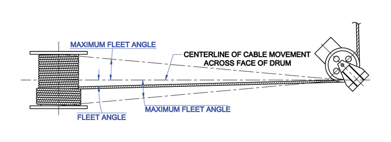
The fleet angle is defined as the largest angle of the rope between the first sheave and the drum flange, relative to the centre line of the drum. With all types of drum, the rope is subject to a fleet angle which directly influences its behaviour and impacts on its service life. If the fleet angle is too big, the wire will tend to pull away from the flange as the layer changes. It will want to spool towards the centre and so leave gaps. Gaps mean ragged spooling, which means (at best) excessive rope wear, or (at worst) snagging, catastrophic system failure and physical danger to all those around.
If the fleet angle is too small, the rope may not pull away from the flange soon enough. It will pile up on the flange for, perhaps, two or three wraps and then bang down with considerable force, damaging the rope and the equipment. Again, catastrophic failure and personal injury is a real threat.
Ideally, the fleet angle should be between 0.25 and 1.25 degrees. This is not an absolute rule of physics; it depends on the rope construction. Nor has it been calculated mathematically. Rather, it has been learned from years of experience. While some wire rope experts may cite slightly different numbers, this is the range that Lebus recommends, and we believe we have at least as much experience as anyone when it comes to multi-layer spooling since inventing the original Lebus counterbalanced spooling system in the 1950s.
The fleet angle can be varied by moving the first sheave closer to or further away from the drum. If the sheave is too close to the drum, the fleet angle will be calculated at greater than 1.25 degrees; if it is too far away, the fleet angle will be less than 0.25 degrees.
In general the distance between sheave and drum should be at least 20 times the width of the drum. Ideally a ratio of 23:1 works very well, we have found. Thus, the larger the drum, the further away the sheave needs to be to keep the fleet angle between 0.25 and 1.25 degrees.
It is not always possible, however, to achieve the optimum fleet angle. For example, there are massive winching systems at the top of mountain cable car systems, often housed in compact machinery sheds. There is often no space to rig a sheave the requisite distance from the drum, and so an alternative for how to reduce the fleet angle must implemented.
For just such cases two additional spooling devices are available. One is a fleet angle compensator, which is driven automatically by the rope tension. The other is a level winder that is mechanically driven. Both offer a solution to guide the cable along the drum between flanges, but each has its advantages and disadvantages.
The fleet angle compensator (FAC) is driven by the movement of the wire rope as it goes through the crossover sections of the drum. As the rope winds or unwinds, the FAC shaft slowly oscillates, allowing its sheave to slide back and forth across the shaft to maintain an optimum fleet angle and guide the rope smoothly onto the drum.
Certain operating conditions are necessary for the Lebus fleet angle compensator to function properly. The rope must go from the drum over the compensator sheave with a minimum contact angle of 60 degrees to a fixed point such as a fairlead or fixed sheave. To avoid excessive angles of the rope on the sheaves, the minimum distance between the fairlead (fixed sheave) and the compensator sheave must be at least six times the drum width. If spooling in multiple layers, the drum must have Lebus-style parallel grooving. For a single layer, helical (screw thread) grooving will also work. As always, there must be sufficient tension on the cable during the spooling operation. We recommend that minimum tension should be 1-2% of the wire rope’s breaking load.
There are three primary advantages of the Lebus fleet angle compensator. First, there is no mechanical connection between the drum and the compensator. Second, installation is easy and quick. And third, it is completely automatic and, after initial adjustments when the rope is first spooled onto the drum, only a minimum of maintenance is necessary.
A mechanical level winder comprises a main shaft (the lead screw) with helical screw grooving along which the rope feeder travels. The rope feeder housing includes two vertical roller bars and one horizontal roller or, alternatively, a wire rope sheave. The lateral movement of the housing is generated by a chain drive sprocket ratio between drum and lead screw, as shown in the image. The automatic level winder fitted is designed and engineered to be compatible with the grooving on the drum. Perfect, controlled spooling is guaranteed regardless the number of layers and slight changes in wire rope size.
The level winder unit – also sometimes called level wind pay-on gear – must be installed in front of the drum in line with the first fixed sheave when using the vertical rollers to guide the wire rope.
The level winder is engineered to be compatible with the parallel grooving on the drum. It is adjusted for the specific rope diameter, and the gear ratio is fixed (using a standard sprocket-chain connection) to match the ratio between coils of wire on the drum to the pitches on the lead screw. The result is perfect and controlled spooling, regardless of the number of layers or slight changes in wire rope size.
As before, certain operating conditions are required for the level winder to function properly. The rope must go from the drum through the vertical rollers or the level-wind sheave to a fixed point such as a fairlead or fixed sheave. To avoid excessive angles of the rope on the sheaves, the minimum distance to the fairlead or fixed sheave must be at least seven times the drum width. There must be a minimum tension of 1 to 2% of the wire rope’s breaking load when spooling more than one layer.
The advantages of level winders are that they keep the rope spooling properly even if there is slack in the line. As with the fleet angle compensator, once it is set up no more adjustment is necessary and very little maintenance is required. In case of damage to a mechanical level winder, parts are easy to replace and there is nothing electrical or hydraulic to worry about.
Oceanographic installations that spool rope up to 46 layers have demonstrated that level winders give synchronised and totally controlled spooling in the very harshest, most testing conditions.
The disadvantages of level winders is that they do require a little more space than fleet angle compensators and they are sensitive to high axial forces and shock loads.
If the fleet angle is just a bit too small, there is a really rather simple solution. A flat iron plate, which we call a kicker plate, is welded or bolted onto a specific point on the flange of the winch drum. This kicker costs no more than two dollars. Since the Lebus parallel grooving pattern on the drum controls the movement and spacing of the wire rope between the flanges, and from layer to layer, it is easy to identify the location on the drum circumference where the rope must return (kick back) from the flange to regain the proper position to assure proper spooling for each repeated layer.
This is where the kicker is placed. Once installed near the centre line of the groove crossover sections, the rope is given a kick after each complete wrap to take its proper position on the patterned drum.
A final option for adjusting the fleet angle, if it is not possible to move the fixed sheave, is simply to reduce the width between the flanges. The parallel grooving of the drum will continue to act effectively to provide smooth multi-layer spooling with a narrower drum, even if – as is likely – the number of layers on the drum needs to increase as a consequence of narrowing the width.

Multi-layer drum systems should use strand- or swage compacted Python® rope constructions having a steel core. The higher fill factor of such rope constructions will offer a greater resistance to crushing and flattening than conventional rope types. This is particularly important for boom hoist ropes on lattice boom cranes at the cross over point from one rope winding to the next.
Cranes equipped with multi-layer drum systems which require rotation-resistant or non-rotating rope are best served with Python Compac® 18 and Compac® 35. To further reduce drum crushing have the rope layers wound onto the drum with about 5-10% of the WLL and avoid that the first layer unspools and re-spools without tension. This would cause a ‘soft’ bottom layer which will flatten the rope.
This one is about Fleet Angles on Wire Rope. An important topic in any wire rope reeving system, this article looks at fleet angles both at the drum and at the sheave.
Fleet Angle is usually defined as the included angle between two lines, one which extends from a fixed sheave to the flange of a drum and the other which extends from the same fixed sheave to the drum in a line perpendicular to the axis of the drum.
When spooling wire rope onto a smooth/plain drum it is generally recommended that the fleet angle is limited to between 0.5 and 2 degrees. If the fleet angle is too small, ie less than 0.5 degrees, the rope will tend to pile up at the drum flange and fail to return across the drum. In this situation, the problem may be alleviated by increasing the fleet angle through the introduction of a sheave or spooling mechanism.
If the rope is allowed to pile up it will eventually roll away from the flange, creating a shock load in both the rope and the drum assembly, thus creating an undesirable and unsafe operating condition.
Excessively high fleet angles will return the rope across the drum prematurely, creating gaps between wraps of rope close to the flanges as well as increasing the pressure on the rope at the cross-over positions.
Where drum grooving is provided, large fleet angles will result in wear taking place to the drum grooving which may then result in the rope miss-spooling on the drum. When spooling onto a grooved drum, it is recommended that the fleet angle is limited to between 0.5 and 4 degrees for 6&8 stranded single layer construction wire ropes and between 0.5 and 2 degrees for rotational resistant and parallel laid construction wire ropes. Note, for high speed spooling of wire rope in excess of 8m per second it may be necessary to reduce the fleet angle to 0.5 to 1.5 degrees especially at high D/d ratios.
Level winding/spooling mechanisms can be positioned in front of a wire rope winch drum to guide the rope across the face of the drum to provide superior spooling utilising fleet angles between 0.25 and 1.5 degrees
When a fleet angle exists as the rope enters a sheave, it initially makes contact with the sheave flange. As the rope continues to pass through and around the sheave it moves down the flange until it sits in the bottom of the groove. In doing so, even when under tension, the rope will actually roll as well as slide. As a result of the rolling action the rope is twisted where turn is induced into or out of the rope. This either shortens or lengthens the lay length of the outer strands which can damage the rope and cause ‘birdcages’ or similar distortions within the rope. A s the fleet angel increases so does the amount of twist
The fleet angle within the reeving system should be limited to 4 degrees for 6 & 8 stranded single layer construction wire ropes and 2 degrees for rotational resistant and parallel laid construction wire ropes. It is recognised that it is not always possible to comply with these general recommendations. This may be the case in applications such as overhead hoists. In which case the rope life can be affected.
Please do not hesitate to contact the team at Crane Ropes Australia or give us a call at LiftQuip on 7089 8335 if you would like more clarification or would like to work through some technical issues you may be having with your wire rope.

It’s a good piece of information to have in your back pocket when you are adjusting or inspecting your rigging, or if you have the opportunity to buy a new rigging system. If you notice an excessive fleet angle, it could be a clue that something is wrong with your mounting or machinery.
In a properly installed manual lineset, the cable comes out as parallel to the groove of the block as possible. It can form an angle of 1.5 degrees into or out of the block, but no more—if the angle is greater, the cable will rub against the sheave. This can cause the cable to fray and eventually break, which can bring scenery or stage weights down on someone’s head.
Chances are you’ve seen the term zero fleet angle in articles or advertising for motorized rigging equipment. A hoist with zero fleet angle has a non-moving set of blocks above the drum. As the drum turns, it actually moves, so the cable piles on and off of the drum with no change in the angle between the drum and the cable.
Zero fleet angle hoists can be installed in greater density than other drum or line shaft hoists—allowing for more sets on stage. These hoists are particularly useful in renovations of historic theatres, where there may be minimal loft space.
The primary purpose of the LeBus Spooling System is to spool wire rope or cable onto hoisting drums in a true and correct manner. In most spooling operations, you never encounter severe spooling problems when spooling only one layer of cable on your drum. In all other cases, your trouble will begin when you start the second layer and from there on up through your last layer.
The LeBus System is the only system on the market that can eliminate the 360o continuous cross winding of the cable as found on smooth drums. The LeBus System cuts down the cross winding to approximately 20% of the circumference of the drum while 80% of the wraps are parallel with the flanges. In view of this pattern, each layer of wire rope then becomes the groove pattern for each succeeding layer.
The LeBus pattern puts the same number of coils on each layer thereby eliminating the "cutting-in" of the cable. This severe scrubbing action can cause the wire rope to fail prematurely. The LeBus System is the only known method that can accomplish this feat. Therefore it creates a much safer environment. Another benefit is increased wire rope life. Since the wire is not "cutting in" and scrubbing on itself, the true pyramid stacking pattern promotes long rope life.

The name LeBus has been around the oil field industry since it was just a blacksmith shop in 1900. LeBus started out by manufacturing speciality tools for the booming west Texas oil fields. Tool pushers and/or owners would see a specific need for a new tool and LeBus would forge the new tools on demand. Soon LeBus was into the manufacturing and selling of fishing tools, drill collars, tool joints and rotary bits. LeBus manufactured the "Eureka Pipe Wrench" and the "Slip Socket Overshot". The common element in each case was the hoisting machinery, specifically the drum and wire rope, which was the main "workhorse" of the drilling rig. LeBus noticed that the wire rope would not lay in a consistent pattern on the drum. This caused undue wear and scrubbing of the wire rope. Something better was on the horizon.

The achievement of even winding on a smooth faced drum is closely related to the magnitude of the D/d ratio, the speed of rotation, load on the rope, and the fleet angle. Of all these factors, the one that exerts perhaps the greatest influence on winding characteristics is the fleet angle.
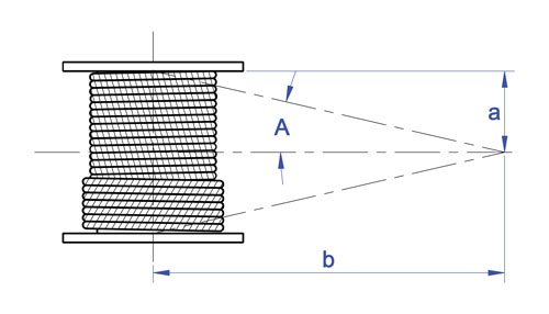
The schematic drawing (Fig. 39) shows an installation where the wire rope runs from a fixed sheave, over a floating sheave, and then on to the surface of a smooth drum. The fleet angle (Fig. 39) may be defined as the included angle between two lines; one line drawn through the middle of the fixed sheave and the drum – and perpendicular to the axis of the drum and a second line drawn from the flange of the drum to the base of the groove in the sheave. (The drum flange represents the farthest position to which the rope can travel across the drum.) There are left and right fleet angles, measured to the left or right of the center line of the sheave, respectively.
It is necessary to restrict the fleet angle on installations where wire rope passes over the lead or fixed sheave and onto a drum. For optimum efficiency and service characteristics, the angle here should not exceed 1 1/2º for a smooth drum, or 2º for a grooved drum. Fleet angles larger than these suggested limits can cause such problems as bad winding on smooth drums, and the rope rubbing against the flanges of the sheave grooves. Larger angles also create situations where there is excessive crushing and abrasion of the rope on the drum. Conversely, small fleet angles – less than 1/2º – should also be avoided since too small an angle will cause the rope to pile up.

The fleet angle Ø, as displayed in FIGURE 2, governs the position of the lead sheave with respect to the drum. When the rope is at one end of the drum, against the drum flange, this fleet angle may not exceed one and a half degrees (1.5˚) for plain drums to two degrees (2˚) for grooved drums left or right from the centre line passing through the centre of the sheave groove and the midpoint of the drum.
Fleet angles larger than these suggested parameters can cause bad rope winding on drums and the rope can rub against the flanges of the sheave groove.
PREFORMING: A manufacturing process wherein the strands and their wires are permanently formed, during fabrication, the helical shape that they will ultimately assume in the finished wire rope. Proper preforming prevents the strand and wire from unlaying during normal use. The vast majority of wire ripe sold today is preformed.
FINISH: Wire rope is either sold as “bright” (or “black”), meaning uncoated, or galvanized for better corrosion resistance. “Drawn Galvanized” wire has the same strength as bright wire, but wire, “galvanized at finished size” is usually 10% lower in strength. Plastic coated wire rope is also available, usually galvanized or stainless steel cable. The most common plastic coverings are vinyl or nylon in either clear or white, although other materials and colors are available. These coating do not add strength to the wire rope itself.
LUBRICATION: During fabrication, wire ropes receive lubrication. The kind and amount depends on the rope’s size, type a use, if known. This in-process treatment will provide the finished wire rope with ample protection for a reasonable time if it is stored under proper conditions. But, when the wire rope is put into service, the initial lubrication will normally be less than needed for the full useful life of the wire rope. Because of this, periodic applications of a suitable wire rope lubricant are necessary.
ORDERING WIRE ROPE: Construction, lay, core, finish and other factors mentioned above impart greatly differing characteristics to different wire ropes. They must be understood and considered when selecting wire rope. There is no perfect wire rope for all applications; usually some less desirable properties are traded off for other, more desirable one. Refer to the Wire Rope Users Manual by the Wire Rope Technical Board for a better understanding of wire rope properties and consult professional help when in doubt.
If a supplier receives an order for 6 x 19 wire rope he may assume this to be a class reference and is, therefore, legally identified in furnishing any construction within this category.

A fleet angle is the angle between the rope leaving the sheave and the centerline of the sheave groove. The fleet angle is important when winding a wire rope on a drum. As the rope is being wound on a drum, it wanders from one side of the drum to the other. Make sure the sheave groove is aligned with the center of the drum to minimize the maximum fleet angle. The maximum fleet angle determines the uniformity of the rope wound on the drum. If the fleet angle is small enough, the rope will wind on uniformly. If the fleet angle is too large, it will leave gaps between wraps. These gaps encourage the rope to cut into the underlayers resulting in crushing and pinching of the rope during winching operations. This situation is aggravated by the use of softer synthetic fiber lines. Large fleet angles can also cause excessive abrasion of the rope against the inner surface of the sheave groove and cause the rope to rotate forming hackles and kinks. A levelwind device may be required to ensure uniform winding if a small fleet angle cannot be achieved. This device is usually sold as an option of a deck winch. It consists of a moving sheave mounted on a shaft with diamond-shaped grooves. The shaft rotation is synchronized with the drum rotation such that the diamond grooves push the sheave to align with the wraps on the drum to achieve uniform winding. When using a deck winch with a levelwind, the sheave fleet angle is restricted only by the abrasion and rotation problems mentioned above.
Where space limitations are unrestricted such as on mine hoists, the fleet angle is sometimes as small as 1/2 of 1 degree. This is equivalent to a distance of 115 feet between the drum and the first fixed sheave for each foot of drum width. It represents the minimum below which the rope will not properly wind back from the drum flange after completing one layer.
Most installations do not permit this much distance between the drum and sheave and for average conditions it is considered good practice to keep the fleet angle within 2 degrees for a grooved drum and 1-1/2 degrees for a drum with a smooth face. Two degrees is equivalent to a distance of 29 feet and 1-1/2 degrees is equivalent to 38 feet for each foot of drum width either side of centerline of sheave as illustrated.


 8613371530291