
wire rope fleet angle pricelist

For optimum spooling, the fleet angle should be between 0.25° and 1.5°, depending on the application, load situation, line speed and the rope construction itself. However, it is not always possible to achieve this. In such circumstances, an additional spooling device such as a fleet angle compensator (automatic driven by the rope tension) or a LEBUS diamond screw levelwinder (mechanically driven) must be installed in order to properly guide the cable along the drum between flanges.
The LEBUS fleet angle compensator consists of an ordinary fleeting sheave that is free to rotate and slide on a shaft, which in turn is free to oscillate between eccentric centers. The movement of the sheave along the shaft is entirely driven by the wire rope spooling onto the drum. As the rope winds or unwinds, the shaft slowly oscillates, allowing the fleeting sheave to slide back and forth across the shaft to maintain an optimum fleet angle and guide the rope smoothly onto the drum.
The achievement of even winding on a smooth faced drum is closely related to the magnitude of the D/d ratio, the speed of rotation, load on the rope, and the fleet angle. Of all these factors, the one that exerts perhaps the greatest influence on winding characteristics is the fleet angle.
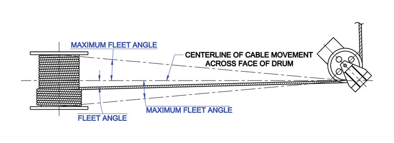
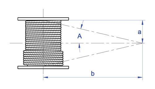
The schematic drawing (Fig. 39) shows an installation where the wire rope runs from a fixed sheave, over a floating sheave, and then on to the surface of a smooth drum. The fleet angle (Fig. 39) may be defined as the included angle between two lines; one line drawn through the middle of the fixed sheave and the drum – and perpendicular to the axis of the drum and a second line drawn from the flange of the drum to the base of the groove in the sheave. (The drum flange represents the farthest position to which the rope can travel across the drum.) There are left and right fleet angles, measured to the left or right of the center line of the sheave, respectively.
It is necessary to restrict the fleet angle on installations where wire rope passes over the lead or fixed sheave and onto a drum. For optimum efficiency and service characteristics, the angle here should not exceed 1 1/2º for a smooth drum, or 2º for a grooved drum. Fleet angles larger than these suggested limits can cause such problems as bad winding on smooth drums, and the rope rubbing against the flanges of the sheave grooves. Larger angles also create situations where there is excessive crushing and abrasion of the rope on the drum. Conversely, small fleet angles – less than 1/2º – should also be avoided since too small an angle will cause the rope to pile up.

In order to insure proper wrapping on the drum and no undue wear of the wire rope, the fleet angle should be kept as small as practical. This is important to consider during the planning of a winch installation. Sheaves and drums should be placed so that the fleet angle will be equal on each side of the centerline of rope travel.
For a smooth drum a maximum fleet angle of 1-1/2 degrees is recommended. When the drum is grooved to suit the wire rope, the fleet angle should not exceed 2 degrees.
*Spliced strength. **ISO strength specifications are for unspliced rope. All other strength specifications are for spliced rope. ADDITIONAL SIZES AVAILABLE UPON REQUEST


 8613371530291