
workover rig base beam brands
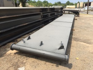
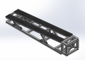
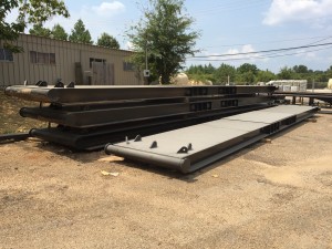
A Base Beam is used on a workover rig for stabilization. They are used in place of ground anchors. Guice Base Beams set the standard for internal guying solutions. They are designed to meet requirements of API RP 4G 14.3. Our beams are proven to decrease rig up and rig down times and will endure the rigorous stresses of the oilfield. We manufacture in-house at GEI Welding. Each beam comes with an assigned serial number to prove it’s a Guice Base Beam.
Guice Base Beams come in 3 standard widths, 2 different variations and can be customized and painted to your specific needs. Base Beam certification is free when manufactured by GEI Welding!

A Base Beam is used on a workover rig for stabilization. They are used in place of ground anchors. Guice Base Beams set the standard for internal guying solutions. They are designed to meet requirements of API RP 4G 14.3. They are proven to decrease rig up and rig down times and can endure the rigorous stresses of the oilfield. Guice Base Beams come in three standard widths: 4, 5, and 6 feet but can also be designed to meet your specific needs. We manufacture in-house at GEI Welding. Each beam also comes with an assigned serial number to prove it’s a Guice Base Beam.
The President of Guice Oilfield: Dr. Lee Guice, PE invented the Guice SRL arm, a Fall Protection arm found on nearly all workover rigs in tight locations.
Our fall protection arm provides extra protection for your employees on the rig. With our staff of experienced licensed Professional Engineers (P.E.) we developed the Guice fall protection systems that meet OSHA, ANSI, ASME conformance.Guice Engineering is always innovating oilfield products with your safety in mind.
The Guice “Razor Ramp” is a short working area lift / ramp combo that ships in one single load. It raises workover rigs 4-8 ft, dependent on design, allowing use of your existing short rigs on most wellheads. With a net lifting load / capacity rated at 130K, the “Razor Ramp” allows 98′-104′ drilling rig to work on deeper holes with higher well head or BOP stacks.
The Guice Engineering cam design provides you multiple heights for multiple jobs. Easy rig up and rig down is achieved with the moving of a single pin. The Hydraulic Catwalk is a self-contained, hydraulic pipe assist machine. The lifting mechanism is designed to create opportunities where big hydraulic operations would otherwise be needed. The Hydraulic Catwalk picks up and lays down pipe rapidly, efficiently, and safely. It reduces personnel time and operation time on site and averts high-risk situations. The Hydraulic Catwalk eliminates costly man hours and strenuous effort by allowing employees to remain and work at a safe distance and avoiding the threat of “falling pipe” and personal harm. The Hydraulic Catwalk provides a safer way to handle pipe in high-risk situations, reducing insurance claims and saving your company money!
The 844 TD-HD Workover Rig by Franks has a 3/4″ Tubing Line, Air Clutches and is powered by a Detroit Diesel 6V71 Motor & Allison CLT 4460 transmission. The 844 TD-HD Workover Rig is in excellent working condition, has a current OK Tag and clean Title.
Performance proven main drum draw works assemblies are modular construction for versatile rig assembly. Designed to allow maximum parts interchangeability and easy add-on features to customize this for your specific operation.
This unit is mounted on a Cabot Explorer carrier designed specifically for oilfield equipment. Rugged walking beam suspension, double reduction rear tandem with Bendix powered air brakes.
This website is using a security service to protect itself from online attacks. The action you just performed triggered the security solution. There are several actions that could trigger this block including submitting a certain word or phrase, a SQL command or malformed data.
WILSON WELL SERVICE RIG (Ref#3000Ta) 103’ x 248,000# derrick, Out of service since 2017, lot of rust, will start and run and/or drive down the road POR
Refurbished, 700 hp, Double drum 2042 drawwroks with Parmac 202 brake assist, (2) Caterpillar 3406 Engines, (2) rebuilt Allison 750 6 speed auto transmission with reverse. 112" x 300,000 # hook load capacity on 8 lines, clear height 97 feet, leg spread 7" 6-1/2", racking board, oil bath chain case, elevated rotary drive, all raising lines and guidelines. The Draw-works, hydro-mantic break, and crown assembly have been rebuilt. Heavy duty Draw works drive propeller shaft through right angle gear box, rotary drive propeller shaft, heavy duty reverse gear box and oil bath roller chain, and a self-locking handling winch. Mounted on triple front axle mechanical 6 axle carrier with 134,000# capacity designed to meet highway safety standards with necessary toughness for off road operations. Price: $265,000
Derrick fell onto rig when being raised, derrick would need to be replaced or repaired. Built 1981, double drum, 42 x 12, 42 x 8, swab drum removed from jack shaft, 5-axle back in carrier, 250,000# derrick with double racking board and triple rod basket, Cat 3408, CLT 5860 transmission, Cooper right angle box, 4 hydraulic leveling jacks, air rod transfer in derrick, hydraulic winch, Kerr 6 cyd 10000 psi Mustang pump powered from jack shaft, Kerr 3-valve release 10,000 psi, tong carrier f/Foster, steel work platform, Parmac 22 SR hydromatic brake. Extra rebuilt 3408 Cat engine. Price as is: $112,500
Manufactured 1981, mounted on 5 axle carrier, double triple service rig, 96’ x 250,000# derrick, Detroit Series 60 12.7 diesel engine, Allison transmission, 9/16” sandline, 1” drill line, hydraulic jacks, hydraulic catwalk, travelling block, tubing bard, rod basket and all necessary lines. Tooling not included. Price: $115,000
Manufactured 1983, double drum, 96’ x 180,000# derrick, mounted on 5 axle carrier with 92T engine, Allison transmission Price rig only: $300,000 Price with tooling:$340,000
WILSON 42 WELL SERVICE RIG(Ref#7562Ta) Manufactured 1975, 180,000# Pemco double/triple derrick, mounted on Wilson carrier with Detroit 8V71 engine, 4 hydraulic leveling jacks, ready to work Price rig only: $74,500 Price with tooling: $94,500
Manufactured 1983, 70" x 120,000# non telescoping stiff mast, double drum 26 x 8, Detroit 6V71 diesel engine, 740 Allison transmission with Spicer power divider, mounted on 4 axle carrier. Rig runs and truck drives, stacked for several years, good condition Price: $93,500 USD
FRANKS 500 WORKOVER RIG(Ref#7615Tc) Built 1980, refurbished 2018, 102’ derrick, 150 ton blocks, 15,000’ sandline, new engine and transmission, ready to work Price: $430,000
FRANKS 400 WORKOVER RIG(Ref#7615Ta) Built 1979, refurbished 2017, 102’ x 215,000# derrick, 100 ton blocks, 15,000’ sandline, 4 lines Price: $390,000
FRANKS 300 SERVICE RIG(Ref#1169Ta) 4-legged derrick, Series 60 Detroit engine, 6850 Allison transmission, blocks, Foster tongs, mounted on 4 axle carrier, working condition Price: $37,500
WILSON MOGUEL 42 WELL SERVICE RIG(Ref#3177Tb) Two available, 96" x 280,000# mast, Detroit Series 60 engine, 5860 Allison transmission, mounted on 5 axle Wilson carrier, handling tools Price: $315,000
WILSON SUPER 38(Ref#3307R) Double drum drawworks, friction clutches, Foster makeup and breakout catheads, Cummins 250 disel engine, Spicer 4 speed transmission, 70’ cantilever mast, 4-sheave crown block, racking board, mounted on 8’W x 22’L tandem axle trailer with folding walkways, mast base, 4 manual jacks, Budd wheels, National Ideal 75 ton 3-sheave block with hook, Price: $45,000
Workover rig with 83’ telescoping derrick, 10’ crown extension, 200,000# lift capacity, 100,000# snubbing capacity. Catwalk with 42’ reach, forward and revere motion, hydraulic pipe slide, six portable pipe racks, powered by workover rig. 5000 ft/lb hydraulic rotary, 15k psi working pressure capability kelly hose, 300 ton mast with 5 x 5 heavy wall box tubing and 2 x 2 heavy wall cross sections, (2) mast raising cylinders, 9-1/8 x 25’ telescoping cylinders/crown sheaves with cable guides, (2) winch sheaves/snubbing sheaves, SRS fall protection, retractable flow tube design, non-swivel boom pole on curb side winch, (2) mast supports, 1” lifting cables, mounted on 5 axle Crane Carrier (3rd axle drop), with 375k Volvo Penta engine, 150 gal fuel capacity, hydraulic self-leveling components, 6 speed Allison transmission, 1:1 gear box, (2) 65 gpm pumps, (2) 30 gpm pumps, (1) 28 gpm Commercial shearing pump, 40 gal accumulator storage, single man cab, hydraulic leveling jacks Price on Request
Manufactured 1960’s, double drum, single rig mast, 64’ x 250,000# (tubing and rod racks), 70 ton blocks, 2 lines, Detroit diesel 60 gpm @ 2000 psi, hydraulic system, air clutch. Rig was refurbished 2013/2014 at a cost of $130,000: repairs included used 65’ derrick installed, new 1” main line, repairs to air system, hydraulic system upgrade, leveling jacks, derrick ljghting, tires, 70 ton blocks installed. But the rig has been sitting since 2015 and now needs rebuilding. It doesn’t run. Price as is: $19,500
Manufactured 1980, completely refurbished 2004, 5 axle double drum well service unit, double 15 Parmac brake on main drum, 96" x 180,000# hydraulic raised mast, mast lighting, Detroit 60 Sereis engine, 5860 Allison 6 speed transmission, 4 hydraulic leveling jacks, dual manual outriggers, PD12 Braden utility winch, McKissick 100 ton tubing block 21-31 diving, 1000" of 1" tubing line, 13000" of 9/16" sandline Price: $225,000
CARDWELL KB200B SERVICE RIG(Ref#11674Ta) 72’ x 140,000# stiff mast, 40 x 10 double drum drawworks, 2 aux deck winches, tubing board, rod board, cat walks, railing, stairs, floor BOP controls and accumulator bottles, McKissick 75 ton tubing block and hook, mounted on 5 axle carrier, Detroit 8V71 diesel engine, Alliston CLBT4460 auto transmission PRICE: $127,500
Rig manufacture 1980, mounted on 1980 GMC Brigadier with Cat 3208 engine, includes elevators & misc tools, also includes 1996 1-ton Super Duty tool truck, tandem axle, Cat 3208 diesel, sitting 1-1/2 years Price: $92,500
1980, 475 hp, single drum (new), reworked, 96" x 205,000# hydraulically raised mast, 6 lines, crown block: 3 new sheaves blocks and bearings, racking board, guide wires, (2) hydraulic hoist, weight indicator, block, elevator links, fall safety device, work platform, mounted on 4 axle carrier with Detroit Series 60 diesel engine, Allison transmission, rig in excellent condition and has been well maintained, ready for use PRICE: $115,000
SKYTOP BREWSTER RR400(Ref#13190T) Mounted on 4 axle carrier, single drum drawworks, 8x7 disc assisted brakes, tubing board, Cat3406B engine, Allison 860DB transmission, 100 ton McKissick block, Foster 58-92R tongs, misc hand tools, approx 36" base beam for rig, ready to work Price: $110,000
Refurbished 2017, 4 lines, 96’ x 205,000# mast, 8V71 Detroit engine, mounted on CCC, 75 ton McKissick blocks, tubing board, rod basket, work platform, rigged up and working in field Price: $295,000
Manufactured 1977, 72’ x 125,000# derrick, 8V71 Detroit engine (rebuilt), Allison 750 transmission, 6500’ of new 5/8” sand line, tubing line new, drum brakes new, new style McKissick blocks, working daily Price rig only: $157,500
Double drum drawworks with hydromatic brake, 10" brakes, 96" x 180,000# derrick, mounted on 4-axle PEMCO carrier with hydraulic support legs, 8V71 Detroit, 4460 Allison transmission, Spicer 784 split shaft gearbox, 250 hp right angle drive, 650" of 7/8" tubing line, 8000" of 9/16" swab line, 100 ton Sowa block, hydraulic winch, hydraulic weight indicator, 84" links, 2-3/8" and 2-7/8" tubing elevators, BJ tubing slips, Foster 5893R power tongs with lift in derrick, rod hook, rod stripper, rod elevators, wrenches, transfers, rod fishing tools, misc hand tools and connections Price: $140,000
Manufactured 1974, double drum drawworks, double triple 96" x 180,000# derrick with a hydromatic. The rig has working line with heavy traveling block and approx. 12,000" 9/16 sand line. Mounted on Skytop carrier with tandem steering and rear ends 4 axles W/ tag axle, 4 leveling jacks, powered by an 8V-71 with a Allison 4460 transmission, (note transmission was overhauled in early 2000"s) and the engine has a new head on right bank. The rig has two leveling jacks on the rear and two leveling jacks on the front which are located right behind the steering axels. Tooled out with hydraulic rod and hydraulic tubing tongs, air slips, rod and tubing elevators, hand tools and misc over items. PRICE REDUCED: $115,000
10 x 13 pole, double Drum, Franks 33” air over grease, brakes in good shape, 7/8” tubing line, tubing blocks, tong pressure adjustment, hi/low on tubing, air slips control, master kill on drawworks, Foster 36 with 8’ lift ram, air backup, swing around tong rack, mounted on 2001 Freightliner F80 truck, Cat C12 Series 3125, Fuller 9-speed transmission, PTO, winch for pole scope Tulsa 48, blocks raise pole, dual fuel tank, dual battery, 50 gal hyd tank, toolboxes, hydraulic outriggers, BJ rod tongs, ¾” and 7/8” heads, tools, swabs, extra tongs, orbits, drilling head Price: $242,500
Double drum (second drum is removed, rig is running as single drum), hyd pole and down riggers, mounted on 1990 Crane Carrier, 9 sp Eaton Fuller transmission, 100,000 miles, 8 x 10 telescoping poles, 3/4” cable, no tooling Price: $52,500
10 x 13” pole, single drum, mounted on 1980 Brigadier 9500 Series truck with 671 inline Detroit, drop box, travelling blocks, tubing lines, hyd jacks, no tooling, sitting since 2000 PRICE: $49,500
Cable Tool Drilling and Completion Rig, 60" double poles rated to 150,000#, 5000" drill capacity, 10,000" pull capacity, propane Waukesha 145 engine, 500 gal propane tank, trailer moutned with International 4300 truck, last drilled 2012, 2300" drill line on drum, 3500" on spool casing drum, heavy block sandline drum, cat heads each side, tooling, spare engine Price: $72,500
400’ of 7/8” block line, 9/16” sandline drum (no cable), 2000’ of ¾” drilling drum, 3 McKissick sheaves, air clutches and controls, mounted on 1961 Mack truck with 250 hp Cummins engine, older rig but runs good. Includes elevators, oil saver pump, no BJ tongs, currently working. Price: $87,500 - Pennsylvania
Triple drum, friction clutch, cathead (sandline holds 2400’ of 5/8” line), mounted on tandem axle Chevy truck with 427 gasoline engine, 8-5/8” x 45’ single pole, new tires, power steering, wireline unit, good usable rig for shallow oil/gas lease, drills, workover, swab capabilities, no tools Price: $112,500 - Oklahoma
Dragon manufactures a full line of 300 to 1,000 HP Cooper ™ Rigs at our state-of-the-art U.S. facility and our rig team is one of the most seasoned in the industry. Whether you need a used well servicing rig, a workover rig, a drilling rig, mud pumps and systems or parts and service, Dragon has you covered.
Our expansive inventory of parts and accessories includes mud systems, mud hoppers and mud guns, agitators, pipe racks, draw works, API 4F, 4th Edition certified masts, break blocks, McKissick tubing and drilling blocks and refurbished gear boxes for most brands of well servicing units. Our rig masts have a clearance height range of 71-124′ and capacities of 150,000 lbs too 500,000 lbs.
Like all Dragon equipment our used Cooper Workover Rigs are severed duty engineered. We also have hands-on experience building to severe, cold weather specs and in compliance with the state of California’s requirements. When you buy a Cooper™ Rig from Dragon you get a custom, easy to operate, safe rig at a competitive price. Whatever mobile rig solution you need, Dragon will build it, deliver it and back it with the highest level of service and support in the industry.
Manufacturer of standard & mobile rigs & carriers for oilfield applications. Includes well servicing from 14,000 ft. to 22,000 ft., workovers from 10,000 ft. to 16,000 ft. & drilling from 6000 ft. to 10,000 ft. Specifications include brakes range from 28 in. dia. x 8 in. wide to 42 in. dia. x 12 in. wide, barrels from 12 3/4 in. x 38 in. to 18 in. x 43 in., chains from 1 1/4 in. to 1 3/4 in., clutches of 24 in. with single & 2 plate air friction outboards, shafts of 5 in. dia. to 6 1/2 in. dia. & gross weights from 63,200 lbs. to 115,000 lbs. Also includes forged steel, demountable options, mufflers with spark arrestors, dry type air cleaners, transmissions with torque converters, water splash brake cooling & up to 6 axles.
To ensure our website performs well for all users, the SEC monitors the frequency of requests for SEC.gov content to ensure automated searches do not impact the ability of others to access SEC.gov content. We reserve the right to block IP addresses that submit excessive requests. Current guidelines limit users to a total of no more than 10 requests per second, regardless of the number of machines used to submit requests.
We have a great team that provides Work Over Rigs. The rigs are 2012 Cooper 550"s. Derrick 104" with 250,000 hook and load capacity on 8 lines. Derrick 116" with 250,000 hook and load capacity on 8 lines with 10k pump package. 500HP series 60 with Allison Transmission. 440 Triplex mud pumps with 500HP, full 5 valve manifold with 6000psi valves supplied with choke and inserts.

SCOPE: To provide a representative basis for determining the availability, capability, dependability, reliability of Stability Systems on Land Based Work-Over Rigs and the recommended practices and procedures for their safe use.
The rig location area may grade away from the well bore along centerline II at a maximum drop of 1:20. The cross grades, parallel to centerline I, should be level. The area shall provide a minimum bearing capacity of 6000 psf.
The flat plate anchor is stamped from metal plate then folded into a reduced profile for insertion into the ground. The flukes are expanded into undisturbed soil, again by tamping or impact, to provide the holding power for this type of anchor. A base plate supports the extended flukes providing added strength and stability.
The "Well Head" is located at the center of the Chart. This will be considered the base reference point for positioning of the guy anchors. The holding capacity of the anchors will then be determined by the zone in which they are located. ie: A, B, C, or D.
The near parallel baseline of Zone "D" to the cross lines NS and EW is 25 feet. (see Northwest and Southeast Quadrants). The far baseline of Zone "D" to the cross lines is 35 feet. (see Northwest and Southeast Quadrants). The vertical distance from the cross lines to the end of the base line is 60 feet and 85 feet to the end of the far line. The area located within this geometrically angled rectangle, within each quadrant, is the area comprising Zone "D".
Using the chart: An anchor in Zone "A" located a horizontal distance of 70 feet from the "Well Head" would require an anchor of what minimum holding capacity? On the chart move along the horizontal legend from left to right until you reach 70 feet. At this juncture proceed vertical until you intersect the curved line for Zone "A", now follow the intersecting horizontal line, left toward the vertical legend. We have now determined that the minimum holding capacity for the anchor, at this precise location, is 20,000 pounds.
Standing at the "Well Head", with the well bore immediately to your back, proceed North (in direction monkey board is facing) 24 paces. (The pace length is not as important as the numerical relationship of the units and the consistency of the unit length. The method will work with any unit of length as long as the same unit is used throughout.) Place a stake or other marker at this location (Bench Reference). Turn West 90 degrees and proceed forward 10 paces. At this location turn your body so that the front portion of your anatomy is approximately parallel to the radial of the guy anchor. If the northwest guy anchor is forward of your right shoulder and the southeast guy anchor is aft to the rear of your left shoulder, it can then be presumed that the radial angles are within acceptable parameters. Repeat the procedure from the bench reference, this time to the east, proceed ten paces. In this orientation the northeast anchor should be forward of the left shoulder and the southwest anchor should be aft of the right shoulder.
In keeping with the concept, which embraces the acceptance of new and innovative approaches, that are based on sound engineering principals, the following alternative, recommended installation guideline, is presented.
A survey of 13 drilling contractors operation 193 drilling rigs in northern Canada and Alaska indicated that there is a wide range of experience and operating practices under extremely low temperature conditions. While there is very little precise information available, there have been a sizeable number of failures in portable masts while in the lowering or raising process in winter. Thus the exposure to low temperature failures focuses on mast lowering and raising operations. Based on reports, however, this operation has been accomplished successfully in temperatures as low as -50 degrees F. While the risk may be considerably greater because of the change in physical characteristics of steel at low temperatures, operators may carry on "normal" operations even at extremely low temperatures. This may be accomplished by a program of closely controlled inspection procedures and careful handling and operation. This should reduce damage and impact loading during raising and lowering operations. At the present, there seems to be no widely accepted or soundly supported basis for establishing a critical temperature for limiting the use of these oilfield structures. Experience in the operation of trucks and other heavy equipment exposed to impact forces indicates that -40 degrees F may be the threshold of the temperature range at which the risk of structural failure may increase rapidly. Precautionary measures should be more rigidly practiced at this point. The following recommended practices are included for reference:
* Make use of any practical, available means to warm sections of the mast, such as using high pressure steam to heat the points of attachment between the mast and its base; also timber bonfires, and the like.
If maintained to these tolerances the sags will indicate a pretension of 1000 pounds for crown to ground guywires and 500 pounds for tubing board guywires. this is based on the use of 5/8 inch, 6x19, or 6x37 class, regular lay, ips, IWRC wire rope, installed according to the rigging guidelines set forth in chart depicted in Figure 5-5
The drawing on the following page, Figure 5-4, (SAME AS FIGURE 4-4) is another illustration of the continuing evolution of Rig Stability System engineering and design. It represents the latest API thinking relative to planing and preparing a Rig Stability System.
CAUTION: SOLE EMPHASIS SHOULD NOT BE PLACED ON PULL TESTING OR ALTERNATIVES TO PULL TESTING AS THIS MEASURES ONLY ONE COMPONENT OF THE RIG STABILITY SYSTEM.
The rig contractor should be responsible for the following: a. Insuring that anchor capacities are verified and that anchor spacing and capacity is suitable for the mast guying pattern and anticipated loading.
b. Records of pull testing or records of other methods used to verify temporary anchor capacity should be retained by the rig contractor until the job is complete and the guy wires have been removed from the anchors. The records should indicate the capacity of each anchor, the date of verification, name and phone number of the party responsible for verification, and the soil condition at the time of verification.
OUT OF AN ABUNDANCE OF CAUTION IT IS EXTREMELY IMPORTANT TO POINT OUT THAT THE PREVENTION OF RIG UPSET IS DIRECTLY DEPENDENT ON THE TOTAL INTEGRITY OF THE RIG STABILIZATION SYSTEM. THE SYSTEM INCLUDES ALL OF ITS COMPONENTS AND IS ONLY AS SOUND AS ITS WEAKEST MEMBER.
Our research has concluded, that the latest State-of-the-Art in RIG STABILIZATION is to be found in the pending American Petroleum Institute, Recommended Practice for MAINTENANCE and USE of DRILLING and WELL SERVICING STRUCTURES.
Inserting and pulling up pipe tubing from oil wells is a precise and challenging job that not every rig is up for. That’s why you need a mobile workover rig from Dragon to get it done right every time. Our workover rigs are state-of-the-art and ready to tackle even the harshest conditions. A workover rig is perfect for site preparation while a standard mobile oil rig can handle a variety of piping tasks. Need workover rig parts, or service on another mobile rig? Dragon has that covered with our parts selection, too. View all of our workover rigs and other drilling rigs today.

E21B7/023—Drilling rigs characterized by means for land transport with their own drive, e.g. skid mounting or wheel mounting the mast being foldable or telescopically retractable
Improvements to base beams and self-propelled derrick rigs are described. The base beam can have two or more stabilizer arms which can be deployed. The base beam is also designed to support the derrick rig. An optional counterweight assembly can be connected to the front of the rig. The self-propelled derrick rig can be easily and quickly mounted to the base beam, and when mounted, the assembly will be able to withstand high hook loads and wind loading without the danger of the rig coming off of its wheels or falling over.
This disclosure relates to apparatus and methods of stably supporting self-propelled derrick rigs such as workover rigs, drilling rigs, cranes and the like, using a portable base beam. BACKGROUND
A completion or workover rig is used to do repair work on a well, such as tubing or pump replacement. When a workover rig is used to do repair work on a well, the rig must be able to pull weights near the rated capacity of the derrick of the rig, withstand high wind gusts, and otherwise be stably supported. Further, a workover rig should operate to its design capacity on a high frequency basis, and be highly mobile and self-contained.
A trend in workover rigs to maintain mobility and higher load capacities has been to use guy wires to stabilize the rig. The use of guys can significantly increase the rated capacity of the rig without changing the basic design.
However, there are drawbacks to a guy system. For example, guy wires need to be in specific locations for the stability and safe operation of the rig, and setup time is longer with a guy setup due to the specific locations. In addition, workover rigs typically tie off to permanent anchors set in the ground in a rectangular pattern around the well head. However, with the growing utilization of multi-well pads, it is nearly impossible to guy the workover rig to the anchors that were originally set in the ground when the well was drilled.
Solutions have been sought to solve the problem of a workover rig not being able to be supported by permanent anchors. One solution has been to utilize one or more base beams that are heavy, portable structures placed on the ground and to which the workover rig is guyed. Existing base beams have a relatively small footprint as well as set locations with which to attach guy wires, which makes set-up easier and faster. SUMMARY
Improvements to base beams and self-propelled derrick rigs are described. A self-propelled derrick rig as used herein is intended to encompass any type of self-propelled vehicle that has a derrick structure mounted on it which can be moved to a raised position during use, a driver"s cab and an engine for propelling the vehicle. Examples of self-propelled derrick rigs include, but are not limited to, workover rigs, drilling rigs, cranes and the like.
When the self-propelled derrick rig is mounted to the base beam, the assembly will be able to withstand high hook loads and wind loading without the danger of the rig coming off of its wheels or falling over. The self-propelled derrick rig can be easily and quickly mounted to the base beam. The assembly also allows support equipment, for example a portable pipe handling machine in the case of a workover rig, to work alongside it. In addition, the base beam can be transported as a single load on a vehicle, for example on a flatbed truck.
The base beam includes stabilizer arms that are attached, for example pivotally attached, to the base beam to help stabilize the base beam and the rig itself. A height adjustable stabilizer pad can be connected to each stabilizer arm to help level the stabilizer arms and the base beam on the ground.
In addition, to the base beam, a unique counterweight assembly is described that in use is connected to the front of the rig to help stabilize the rig and prevent the front of the rig from coming off of the ground.
In one embodiment, a base beam that is used to support a self-propelled derrick rig includes a longitudinally extending metal main beam having first and second opposite ends, a front side, a back side, a top and a bottom, where the bottom is substantially planar. The main beam includes a central section approximately midway between the first and second ends thereof on which the derrick structure of the rig will be supported. The central section can reinforced between the top and the bottom, and the top of the central section is substantially planar. First and second stabilizer arms are attached, for example pivotally attached or non-pivotally attached, to the main beam. when pivotally attached, the stabilizer arms are pivotable relative to the main beam between a refracted or transport position where the first and second stabilizer arms are generally parallel to the main beam and a fully extended or deployed position where the first and second stabilizer arms are not parallel to the main beam. In addition, at least one guy attachment point is provided on each of the first and second stabilizer arms to allow guys to attach between the derrick structure and the stabilizer arms.
In still another embodiment, an assembly is provided that includes a base beam and a self-propelled derrick rig. The base beam can include a longitudinally extending metal main beam having first and second opposite ends, a front side, a back side, a top and a bottom, and a central section. First and second stabilizer arms can be attached, for example pivotally attached or non-pivotally attached, to the main beam. When pivotally attached, the stabilizer arms are pivotable relative to the main beam between a retracted position where the first and second stabilizer arms are generally parallel to the main beam and a fully extended position where the first and second stabilizer arms are not parallel to the main beam. The self-propelled derrick rig can include a derrick structure adjacent a first end of the rig that is disposed in a raised position, a driver"s cab, and an engine that provides power for propelling the rig. A base of the derrick structure can be supported on the central section of the main beam on the top thereof. In addition, a plurality of guys extend between the derrick structure and the rig, and a plurality of guys extend between the derrick structure and the base beam.
In yet another embodiment, the counterweight assembly includes a sled that has a mechanism to connect the sled to the self-propelled derrick rig. The connection can be the sled simply resting on the front of the rig to weigh down the front end, or the sled can be removably attached to the rig. A plurality of weights are removably disposed on the sled. Each weight is individually separable from the other weights and each weight is individually removable from the sled.
In another embodiment, a method of supporting a derrick structure of a self-propelled derrick rig is provided, where the derrick structure is disposed adjacent to a first end of the rig and is movable between a raised position and a lowered position. In the method, a base beam is arranged on the ground, and stabilizer arms that are pivotally or non-pivotally connected to the base beam are deployed from a retracted position to a fully deployed position. The self-propelled derrick rig is arranged adjacent to the base beam, and the derrick structure of the self-propelled derrick rig is raised to the raised position. A base end of the derrick structure is attached to the base beam. In addition, a plurality of guys are attached between the derrick structure and the remainder of the rig and a plurality of guys are attached between the derrick structure and the base beam.
In another embodiment of a method, a base beam is arranged on the ground, and the self-propelled derrick rig is arranged adjacent to the base beam. The derrick structure of the self-propelled derrick rig is raised to the raised position, and a base end of the derrick structure is attached to the base beam. A plurality of guys are attached between the derrick structure and the remainder of the rig and a plurality of guys are attached between the derrick structure and the base beam. A counterweight assembly is also connected to the rig at a second end thereof opposite the first end and the derrick structure to weigh down the front of the rig. DRAWINGS
As described in further detail below, an improved base beam is described that is used to support a self-propelled derrick rig. A self-propelled derrick rig as used herein is intended to encompass any type of self-propelled vehicle that has a derrick structure mounted on it which can be moved to a raised position during use, a driver"s cab and an engine for propelling the vehicle. Examples of self-propelled derrick rigs include, but are not limited to, workover rigs, drilling rigs, cranes and the like. The self-propelled derrick rig will be described below as, and is illustrated in the drawings as, a workover rig. However, the derrick rig can be any other type of rig that can benefit from being supported using a base beam(s) as described herein.
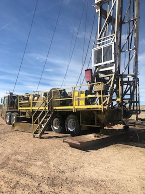
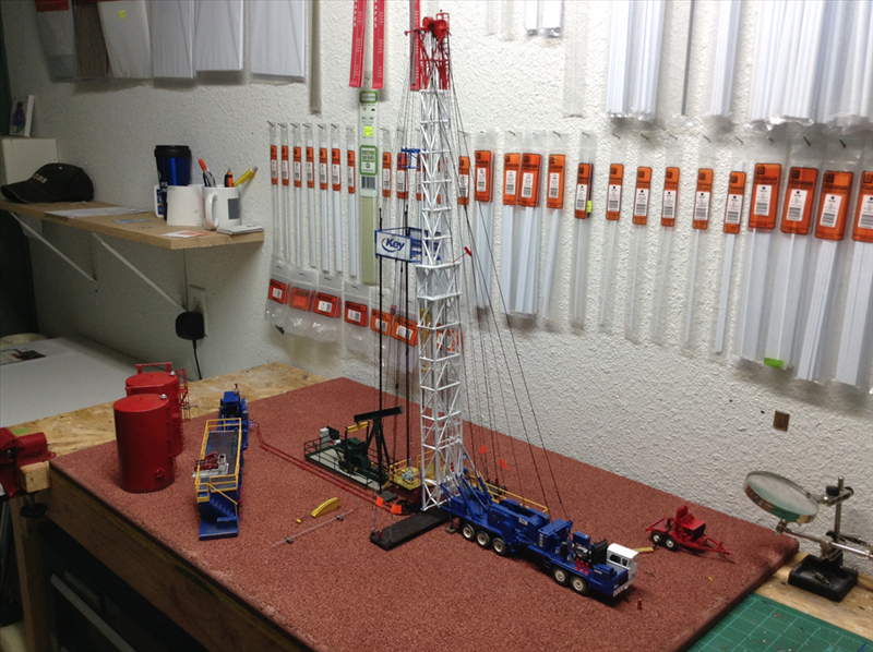
With reference initially to FIG. 1, an assembly 10 is illustrated that includes a base beam 12 that is shown together with a self-propelled derrick rig 14 in the form of a workover rig. The base beam 12 is disposed adjacent to a well head 16, with the rig 14 being used to perform a service function on the well.
The rig 14 includes a derrick structure 18 disposed adjacent to a first or rear end of the rig, where the derrick structure includes a raised position (shown in FIG. 1) and a lowered position (shown in FIG. 4). The rig 14 also includes a platform 20, a driver"s cab 22 disposed on the platform adjacent to a second or front end of the rig, wheels 24 mounted on the platform 20, and an engine 26 adjacent to the front of the rig that provides power for propelling the rig during driving of the rig.
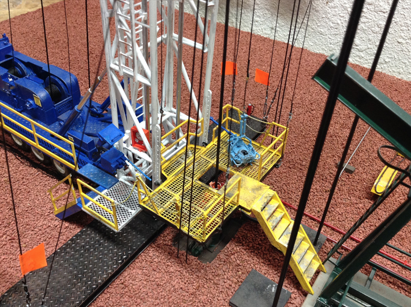
In the raised position of the derrick structure 18 shown in FIG. 1, a base of the derrick structure 18 is supported on the base beam 12. In addition, a plurality of guys 28 extend between the derrick structure 18 and different points on the remainder of the rig 14, and a plurality of guys 30 extend between the derrick structure 18 and the base beam 12.
With reference to FIGS. 2 and 3, the base beam 12 includes a main beam 40 that extends along a longitudinal axis A-A from a first end 42 ato a second, opposite end 42 b.The main beam 40 further includes a front side 44, a back side 46, a top 48 and a bottom (not visible in FIGS. 2-3). The bottom is substantially planar to allow the main beam 40 to lay flat on the ground. In the illustrated example, the main beam 40 is generally rectangular in shape, although other shapes could be used.
The main beam 40 further includes a substantially planar central section 50 approximately midway between the first and second ends 42 a, 42 bthereof. As discussed further below with respect to FIGS. 4-5, in use the central section 50 supports the base of the derrick structure 18. Therefore, if considered necessary to support the derrick structure, the central section 50 of the main beam can be reinforced between the top 48 and the bottom, for example by employing internal reinforcing members disposed within the main beam 40 at the central section 50.
Further, first and second swing or stabilizer arms 52 a, 52 bare pivotally attached to the main beam 40. In the embodiment illustrated in FIGS. 2 and 3, the swing arms 52 a, 52 bare pivotally attached to the main beam adjacent to the first and second ends 42 a, 42 b,respectively. The swing arms are pivotable relative to the main beam 40 between a retracted position (shown in FIG. 2) where the first and second swing arms are generally parallel to the main beam and a fully extended or deployed position (shown in FIG. 3) where the first and second swing arms are not parallel to the main beam.
In an alternative embodiment, the stabilizer arms can be initially separate from the main beam 40 and then attached to the main beam in the extended or deployed position for use. In this embodiment, the stabilizer arms need not be pivotally attached since the arms are attached for use and detached (or not detached) during transport.
In the illustrated embodiment, when fully deployed, the swing arms 52 a, 52 bextend from the front side 44 of the main beam and are disposed at generally right angles to the longitudinal axis A-A. As shown in FIG. 2, each of the first and second swing arms has a length L, and the combined length of the first and second swing arms 52 a, 52 bcan be less than the longitudinal length of the main beam to permit the swing arms to completely fold to the retracted position parallel to the axis A-A. However, as discussed further below, other configurations of the swing arms are possible.
Each swing arm 52 a, 52 bincludes a first swing arm end 54 that is pivotally attached to the main beam, and a second swing arm end 56. A stabilizer pad 58 is connected to the second swing arm end 56 of each swing arm. Each stabilizer pad 58 is adjustable in height to allow leveling of the swing arms and the base beam on uneven ground.
The base beam 12 is constructed primarily of a metal material such as steel. The main beam 40 between the top 48 and bottom is generally hollow. However, if additional weight for the base beam 12 is required, weights that are initially separate from the main beam can be disposed on the main beam adjacent to each of the ends 42 a, 42 b.In one embodiment, concrete can be poured into the hollow interior of the main beam adjacent to the ends 42 a, 42 bto increase the weight of the base beam. In another embodiment, removable weights can be placed on top of the main beam adjacent to the ends thereof. However, any technique for adding weight to the base beam 12 to increase the weight of the beam can be used.
The base beam 12 further includes a plurality of guy attachment points to permit attachment to the guys 30. The guy attachment points can be provided at locations that one determines to be suitable for adequately guying the derrick structure 18. In the embodiment illustrated in FIGS. 2 and 3, there is at least one guy attachment point 60 on each of the first and second swing arms, for example adjacent to the second ends 56. In addition, there can be a plurality of guy attachment points 62 on the main beam 40, for example adjacent to the ends 42 a, 42 b.The guy attachment points 60, 62 can be, for example, flanges that are attached to the base beam 12 and that include a hole to permit attachment of one end of the guys. The guys 30 (as well as the guys 28) can be wires or any structure suitable for use as guys.
Other configurations of the base beam are possible. For example, FIG. 10 illustrates a base beam 212 with a main beam 240 and a pair of swing arms 252 a, 252 bpivotally attached to the main beam 240 for pivoting movement between a retracted position (not shown) where the first and second swing arms are generally parallel to the main beam and a fully extended or deployed position (shown in FIG. 10) where the first and second swing arms are not parallel to the main beam. In this embodiment, the swing arms are pivotally attached to the main beam 240 so that the first and second arms 252 a, 252 bextend from a back side of the main beam when in the fully extended position in a direction generally toward the front end of the rig 14 and parallel to the rig.
FIG. 11 illustrates a base beam 312 with a main beam 340 and two pairs of swing arms 352 a, 352 b, 352 c, 352 dpivotally attached to the main beam 340 for pivoting movement between a retracted position (not shown) where the swing arms are generally parallel to the main beam and a fully extended or deployed position (shown in FIG. 11) where the swing arms are not parallel to the main beam. In this embodiment, the swing arms are pivotally attached to the main beam 340 so that the swing arms 352 a, 352 bextend from a front side of the main beam similar to FIGS. 2-3, while the swings arms 352 c, 352 dextend from the back side of the main beam similar to FIG. 10.
FIGS. 12A and 12B illustrate a base beam 412 with a main beam 440 and two pairs of swing arms 452 a, 452 b, 452 c, 452 dpivotally attached to the main beam 440 for pivoting movement between a retracted position (shown in FIG. 12B) where the swing arms are generally parallel to the main beam and a fully extended or deployed position (shown in FIG. 12A) where the swing arms are not parallel to the main beam. In this embodiment, the swing arms are pivotally attached to the main beam 440 so they extend from the front and back sides of the main beam similar to FIG. 11. In addition, each of the swing arms 452 a, 452 bincludes a first section 454 that is pivotally attached to the main beam and a second section 456 that is pivotally attached to the first section. Constructing the arms 452 a, 452 bwith two sections allows the two sections 454, 456 to fold together, for example one above the other as shown in FIG. 12B, which allows the length of the arms to be increased, while allowing the arm sections 454, 456 to fold to the retracted position.
FIG. 14 illustrate a base beam 512 with a main beam 540 and a pair of swing arms 552 a, 552 bpivotally attached to the main beam 540 for pivoting movement between a retracted position (not shown) where the swing arms are generally parallel to the main beam and a fully extended or deployed position (shown in FIG. 14) where the swing arms are not parallel to the main beam. In this embodiment, the swing arms 552 a, 552 bare pivotally attached to the main beam 540 away from the ends of the beam 540 and more toward the center of the main beam. In addition, the swing arms do not extend at right angles to the main beam as in the other embodiments. Instead, the swing arms 552 a, 552 bare disposed at acute angles a relative to the longitudinal axis of the main beam.
Returning now to FIGS. 1-3 together with FIGS. 4-5, in use, the base beam is transported to a position adjacent to the well head 16 and arranged on the ground. The swing arms are then deployed from the retracted position, which is used during transport of the base beam, to the fully deployed position. If necessary, the stabilizer pads 58 are adjusted in height to level the swing arms and the main beam. The self-propelled derrick rig 14 is then backed up to a position adjacent to the base beam as shown in FIG. 4. During this time, the derrick structure 18 is likely at its lowered or transport position as shown in FIG. 4, although in some circumstances the derrick structure could already be raised or partially raised. If the derrick structure is not raised, the derrick structure is raised to the raised position shown in FIG. 1.
With reference to FIG. 5, once the derrick structure 18 is raised, a base end 70 of the derrick structure is attached to the base beam 12. In particular, one side of the base end 70 is pivotally connected to the rig platform 20 by pivots 72. The other side of the base end is provided with a pair of height adjustable stabilizer pads 74. Metal plates 76 are laid on the top 48 of the main beam at the central section 50, and the pads 74 rest on the plates 74. The base end 70 is fixed to the main beam by one or more fixation members 78. In one embodiment, four fixation members 78 can be used, each of which attaches at one end to the base end 70 of the derrick structure 18 and attach at opposite ends thereof to mounting fixtures 80 that are disposed adjacent to the front side and the back side respectively of the main beam adjacent to, and on opposite sides of, the central section 50. In the illustrated embodiment, the fixation members 78 comprise shackles, although any type of fixation members that can adequately attach the base end of the derrick structure to the main beam can be used.
In addition, as shown in FIG. 1, the guys 28 are then attached between the derrick structure and the remainder of the rig, and the guys 30 are attached between the derrick structure and the base beam. FIG. 1 illustrates the derrick structure 18 as including a rig floor 82 and a tubing or racking board 84 both of which are conventional structures on workover rigs. The guys 28 are illustrated as generally extending from the top of the derrick structure to other points on the rig. Some of the guys 30 extend from the base beam to the top of the derrick structure, while some of the guys 30 extend from the base beam to the tubing board 84 and from the tubing board to the top of the derrick structure. However, the exact arrangement and number of the guys 28, 30 can vary based on a number of factors, such as the expected loading conditions on the derrick structure and the rig. Therefore, the guy arrangement illustrated in FIG. 1 is exemplary only and can vary from the illustrated arrangement both in the number of guys 28, 30 used and their locations.
Under some loading conditions, for example when the derrick structure is pulling at or near capacity, the front end of the rig 14 may want to come off the ground. To prevent such an occurrence, an optional counterweight assembly 90 can be used that is connected to the front end of the rig 14 to weigh down the front of the rig. The assembly 90 can simply connect to the front of the rig by resting on some portion of the front. Alternatively, the assembly 90 can be connected to the rig by removably attaching the assembly to the rig, for example by pinning or bolting the assembly to the rig. Any form of connection can be used as long as the assembly 90 increases the weight of the front of the rig.
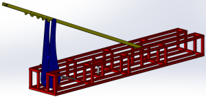
With reference to FIGS. 6-8, the counterweight assembly 90 can include a sled 92 that is designed to connect to the rig 14 and carry separate weights 94 that can be added and removed from the sled 92 to alter the amount of weight carried by the sled.
The sled 92 is a generally rectangular structure that includes a base 96, reinforcing members 98 at each side end of the base, a front side 100 and a rear side 102. The rear side 102 of the sled 92 includes a plurality of vertical beams 104 connected at base ends thereof to the base 96 and at upper ends thereof to a horizontal beam 106. As best seen in FIG. 8, the horizontal beam 106 and/or the beams 104 can be connected to a block, for example of wood, that rests on a ledge at the front of the rig. Thus, the assembly 90 weights down the front end of the rig.
If there is concern that the assembly could move, the assembly could be removably attached to the rig. For example, with reference to FIG. 16, the attachment mechanism can comprise flanges 116 that are fixed to the beam 106 and/or the beams 104, with corresponding flanges 118 on the front of the rig that align with the flanges on the sled. Pins or bolts 119 can then extend through holes in the aligned flanges to attach the sled to the rig.
Each weight 94 is individually separable from the other weights 94 and each weight is individually removable from the sled 92. The weights 94 are generally rectangular in shape and resemble plates. The sled can be designed to hold any number of weights, based in part on how much counterweight one may need.
To aid in mounting, removal and transport of the sled 92, at least two forklift pockets 110 are formed in the base 96. The forklift pockets 110 permit a forklift to lift and transport the sled 92. Similarly, each of the weights 94 includes at least two forklift pockets 112 formed therein. The forklift pockets 112 permit a forklift to lift and transport each of the individual weights 94. Instead of forklift pockets, any structure that performs a function similar to the forklift pockets can be used.
With reference to FIG. 9, the shape of the sled 92 is such that the sled 92 together with any weights held thereon can be disposed on the base beam 12 during transport of the base beam and the counterweight assembly. This minimizes the space taken up during transport.
With reference to FIG. 13, an embodiment is illustrated that uses two base beams. One base beam 120 is substantially similar to the base beam 12. Alternatively, the base beam 120 could be similar to the base beams 212, 312, 412, or 512. A second base beam 122 is disposed underneath the rig 14, for example underneath jacks or outriggers that are provided on the rig 14. The construction and use of jacks or outriggers on rigs is well known in the art. In this embodiment, guys 124 extend from the derrick structure 18 and are connected to the ends of the second base beam 122 to help support the derrick structure.
FIG. 15 shows another embodiment that uses two base beams, including one base beam 130 that is substantially similar to the base beam 12. In this embodiment, a second base beam 132 is disposed underneath the rig 14 at a location that is further forward than the second base beam 122 in FIG. 13. For example, the second base beam 132 can be disposed underneath jacks disposed under the driver"s cab 22, and guys 134 extend from the derrick structure 18 and are connected to the ends of the base beam 132 to help support the derrick structure.
The second base beams 122, 132 illustrated in FIGS. 13-15 are depicted as not including swing arms. However, the second base beams 122, 132 could be configured to have swing arms similar to those discussed above.
a longitudinally extending metal main beam having first and second opposite ends, a front side, a back side, a top and a bottom, the bottom is substantially planar;
the main beam includes a central section approximately midway between the first and second ends thereof, the central section is reinforced between the top and the bottom, and the top of the central section is substantially planar;
first and second swing arms pivotally attached to the main beam, the swing arms are pivotable relative to the main beam between a retracted position where the first and second swing arms are generally parallel to the main beam and a fully extended position where the first and second swing arms are not parallel to the main beam; and
3. A base beam as recited in claim 1, each of the first and second swing arms includes a first swing arm end that is pivotally attached to the main beam, and a second swing arm end; and the guy wire attachment point of each of the first and second swing arms is located adjacent to the second swing arm end.
4. A base beam as recited in claim 1, further comprising weights, separate from the material forming the main beam, disposed on the main beam adjacent to each of the first and second opposite ends.
5. A base beam as recited in claim 3, further comprising a stabilizer pad connected to each swing arm adjacent to the second swing arm end; each stabilizer pad is adjustable in height.
7. A base beam as recited in claim 1, wherein the first and second swing arms are pivotally attached to the main beam so that the first and second arms extend from the front side of the main beam when in the fully extended position.
8. A base beam as recited in claim 1, wherein the first and second swing arms are pivotally attached to the main beam so that the first and second arms extend from the back side of the main beam when in the fully extended position.
9. A base beam as recited in claim 7, further comprising third and fourth swing arms pivotally attached to the main beam, the third and fourth swing arms are pivotable relative to the main beam between a retracted position where the third and fourth swing arms are generally parallel to the main beam and a fully extended position where the third and fourth swing arms are not parallel to the main beam, and the third and fourth swing arms extend from the back side of the main beam when in the fully extended position.
10. A base beam as recited in claim 1, wherein each of the first and second swing arms includes a first section that is pivotally attached to the main beam and a second section that is pivotally attached to the first section.
11. A base beam as recited in claim 1, further comprising first and second mounting fixtures disposed adjacent to the front side and the back side respectively of the main beam adjacent to, and on opposite sides of, the central section.
12. A base beam as recited in claim 1, wherein each of the first and second swing arms has a length, and the combined length of the first and second swing arms is less than the longitudinal length of the main beam.
a longitudinally extending metal main beam having first and second opposite ends, a front side, a back side, a top and a bottom, the bottom is substantially planar; the main beam includes a central section approximately midway between the first and second ends thereof, the central section is reinforced between the top and the bottom, and the top of the central section is substantially planar;
first and second stabilizer arms attached to the main beam, the stabilizer arms extend from the main beam at an angle to a longitudinal axis of the main beam; and
15. A base beam as recited in claim 13, each of the first and second stabilizer arms includes a first stabilizer arm end that is attached to the main beam, and a second stabilizer arm end; and the guy wire attachment point of each of the first and second stabilizer arms is located adjacent to the second stabilizer arm end.
16. A base beam as recited in claim 13, further comprising weights, separate from the material forming the main beam, disposed on the main beam adjacent to each of the first and second opposite ends.
19. A base beam as recited in claim 17, further comprising third and fourth stabilizer arms attached to the main beam, and the third and fourth stabilizer arms extend from the back side of the main beam.
Support arrangement including base support means and elevatable support means to transport a drawworks and drilling mast supported thereon and for positioning at a drilling location

This website is using a security service to protect itself from online attacks. The action you just performed triggered the security solution. There are several actions that could trigger this block including submitting a certain word or phrase, a SQL command or malformed data.
Providing the right equipment and delivering the highest quality, customized services is our priority. Meeting customer needs with efficiency & safety is our aim. We are available 24/7 to provide installation, service and repair to your equipment. At Liberty Lift, we know that when the oil stops flowing, your company stops profiting. Let us help you continue to work quickly, safely and with maximum uptime.Contact Liberty Liftin Midland, Texas, today.
Artificial lift systems are our passion. Oil does not flow naturally from drilled wells, and artificial lift equipment is a key solution to that problem. Efficient and reliable artificial lift operations require the right equipment and servicing. At Liberty Lift, we offer field-proven equipment that has been designed by thoughtful, experienced engineers in the oil and gas industry. We manufacture and offer beam pumping units, hydraulic jet pumps, long stroke pumping units, and gas lift systems that can either be leased or purchased.
To support oil and gas operations, we always have an inventory of necessary equipment so that we can respond in a timely manner. Our inventory includes such things as new and reconditioned beam pumping units, gas lift mandrels and valves, prime movers, concrete bases, Liberty Lift electric motors, arrow gas motors, hydraulic jet pump units, and hydraulic jet pump parts and rental skids. Our cost-effective services would not be complete without the availability of certain equipment, including crane capabilities up to 90 tons, extended reach bucket trucks, and haul trucks (drop deck and float), all of which help our servicing initiatives to be conducted and completed timely and effectively.
With 30 years of experience in designing, manufacturing and testing our beam pumping units, we offer several options to meet most requirements. Our High Efficiency (HE) and Enhanced Geometry (EG) beam pumping units offer the following:
Among other benefits specific to HE and EG beam pumping units, our units also feature gear reducers, equalizer bearing assembly, saddle bearing assembly, wrist pin assembly, brake assembly, and counterweight calibration capability. You can checkour site to learn more about the specifics of each HE and EG beam pumping unitsand review the specifications accordingly.
If you are in the business of gas or oil production and conduct drillings, have an oil rig, need parts or repairs, among other many tasks and operations, we havethe equipment you needto get the job done right.
Our XL Long Stroke pumping unit solves problems. Due to fewer cycles, problems with rods, tubing and workover frequency are reduced. Among other benefits, this unit features top sprockets, a counterweight box, gear reducers, top drum supported by two self-aligning double-row spherical roller bearings, and unit sentry operational safety monitoring, in addition to all the standard features of a long stroke pumping unit. Learn more about ourXL Long Stroke pumping units.


 8613371530291