
workover rig base beam free sample
A Base Beam is used on a workover rig for stabilization. They are used in place of ground anchors. Guice Base Beams set the standard for internal guying solutions. They are designed to meet requirements of API RP 4G 14.3. Our beams are proven to decrease rig up and rig down times and will endure the rigorous stresses of the oilfield. We manufacture in-house at GEI Welding. Each beam comes with an assigned serial number to prove it’s a Guice Base Beam.
Guice Base Beams come in 3 standard widths, 2 different variations and can be customized and painted to your specific needs. Base Beam certification is free when manufactured by GEI Welding!
E21B7/023—Drilling rigs characterized by means for land transport with their own drive, e.g. skid mounting or wheel mounting the mast being foldable or telescopically retractable
Improvements to base beams and self-propelled derrick rigs are described. The base beam can have two or more stabilizer arms which can be deployed. The base beam is also designed to support the derrick rig. An optional counterweight assembly can be connected to the front of the rig. The self-propelled derrick rig can be easily and quickly mounted to the base beam, and when mounted, the assembly will be able to withstand high hook loads and wind loading without the danger of the rig coming off of its wheels or falling over.
This disclosure relates to apparatus and methods of stably supporting self-propelled derrick rigs such as workover rigs, drilling rigs, cranes and the like, using a portable base beam. BACKGROUND
A completion or workover rig is used to do repair work on a well, such as tubing or pump replacement. When a workover rig is used to do repair work on a well, the rig must be able to pull weights near the rated capacity of the derrick of the rig, withstand high wind gusts, and otherwise be stably supported. Further, a workover rig should operate to its design capacity on a high frequency basis, and be highly mobile and self-contained.
A trend in workover rigs to maintain mobility and higher load capacities has been to use guy wires to stabilize the rig. The use of guys can significantly increase the rated capacity of the rig without changing the basic design.
However, there are drawbacks to a guy system. For example, guy wires need to be in specific locations for the stability and safe operation of the rig, and setup time is longer with a guy setup due to the specific locations. In addition, workover rigs typically tie off to permanent anchors set in the ground in a rectangular pattern around the well head. However, with the growing utilization of multi-well pads, it is nearly impossible to guy the workover rig to the anchors that were originally set in the ground when the well was drilled.
Solutions have been sought to solve the problem of a workover rig not being able to be supported by permanent anchors. One solution has been to utilize one or more base beams that are heavy, portable structures placed on the ground and to which the workover rig is guyed. Existing base beams have a relatively small footprint as well as set locations with which to attach guy wires, which makes set-up easier and faster. SUMMARY
Improvements to base beams and self-propelled derrick rigs are described. A self-propelled derrick rig as used herein is intended to encompass any type of self-propelled vehicle that has a derrick structure mounted on it which can be moved to a raised position during use, a driver"s cab and an engine for propelling the vehicle. Examples of self-propelled derrick rigs include, but are not limited to, workover rigs, drilling rigs, cranes and the like.
When the self-propelled derrick rig is mounted to the base beam, the assembly will be able to withstand high hook loads and wind loading without the danger of the rig coming off of its wheels or falling over. The self-propelled derrick rig can be easily and quickly mounted to the base beam. The assembly also allows support equipment, for example a portable pipe handling machine in the case of a workover rig, to work alongside it. In addition, the base beam can be transported as a single load on a vehicle, for example on a flatbed truck.
The base beam includes stabilizer arms that are attached, for example pivotally attached, to the base beam to help stabilize the base beam and the rig itself. A height adjustable stabilizer pad can be connected to each stabilizer arm to help level the stabilizer arms and the base beam on the ground.
In addition, to the base beam, a unique counterweight assembly is described that in use is connected to the front of the rig to help stabilize the rig and prevent the front of the rig from coming off of the ground.
In one embodiment, a base beam that is used to support a self-propelled derrick rig includes a longitudinally extending metal main beam having first and second opposite ends, a front side, a back side, a top and a bottom, where the bottom is substantially planar. The main beam includes a central section approximately midway between the first and second ends thereof on which the derrick structure of the rig will be supported. The central section can reinforced between the top and the bottom, and the top of the central section is substantially planar. First and second stabilizer arms are attached, for example pivotally attached or non-pivotally attached, to the main beam. when pivotally attached, the stabilizer arms are pivotable relative to the main beam between a refracted or transport position where the first and second stabilizer arms are generally parallel to the main beam and a fully extended or deployed position where the first and second stabilizer arms are not parallel to the main beam. In addition, at least one guy attachment point is provided on each of the first and second stabilizer arms to allow guys to attach between the derrick structure and the stabilizer arms.
In still another embodiment, an assembly is provided that includes a base beam and a self-propelled derrick rig. The base beam can include a longitudinally extending metal main beam having first and second opposite ends, a front side, a back side, a top and a bottom, and a central section. First and second stabilizer arms can be attached, for example pivotally attached or non-pivotally attached, to the main beam. When pivotally attached, the stabilizer arms are pivotable relative to the main beam between a retracted position where the first and second stabilizer arms are generally parallel to the main beam and a fully extended position where the first and second stabilizer arms are not parallel to the main beam. The self-propelled derrick rig can include a derrick structure adjacent a first end of the rig that is disposed in a raised position, a driver"s cab, and an engine that provides power for propelling the rig. A base of the derrick structure can be supported on the central section of the main beam on the top thereof. In addition, a plurality of guys extend between the derrick structure and the rig, and a plurality of guys extend between the derrick structure and the base beam.
In yet another embodiment, the counterweight assembly includes a sled that has a mechanism to connect the sled to the self-propelled derrick rig. The connection can be the sled simply resting on the front of the rig to weigh down the front end, or the sled can be removably attached to the rig. A plurality of weights are removably disposed on the sled. Each weight is individually separable from the other weights and each weight is individually removable from the sled.
In another embodiment, a method of supporting a derrick structure of a self-propelled derrick rig is provided, where the derrick structure is disposed adjacent to a first end of the rig and is movable between a raised position and a lowered position. In the method, a base beam is arranged on the ground, and stabilizer arms that are pivotally or non-pivotally connected to the base beam are deployed from a retracted position to a fully deployed position. The self-propelled derrick rig is arranged adjacent to the base beam, and the derrick structure of the self-propelled derrick rig is raised to the raised position. A base end of the derrick structure is attached to the base beam. In addition, a plurality of guys are attached between the derrick structure and the remainder of the rig and a plurality of guys are attached between the derrick structure and the base beam.
In another embodiment of a method, a base beam is arranged on the ground, and the self-propelled derrick rig is arranged adjacent to the base beam. The derrick structure of the self-propelled derrick rig is raised to the raised position, and a base end of the derrick structure is attached to the base beam. A plurality of guys are attached between the derrick structure and the remainder of the rig and a plurality of guys are attached between the derrick structure and the base beam. A counterweight assembly is also connected to the rig at a second end thereof opposite the first end and the derrick structure to weigh down the front of the rig. DRAWINGS
As described in further detail below, an improved base beam is described that is used to support a self-propelled derrick rig. A self-propelled derrick rig as used herein is intended to encompass any type of self-propelled vehicle that has a derrick structure mounted on it which can be moved to a raised position during use, a driver"s cab and an engine for propelling the vehicle. Examples of self-propelled derrick rigs include, but are not limited to, workover rigs, drilling rigs, cranes and the like. The self-propelled derrick rig will be described below as, and is illustrated in the drawings as, a workover rig. However, the derrick rig can be any other type of rig that can benefit from being supported using a base beam(s) as described herein.
With reference initially to FIG. 1, an assembly 10 is illustrated that includes a base beam 12 that is shown together with a self-propelled derrick rig 14 in the form of a workover rig. The base beam 12 is disposed adjacent to a well head 16, with the rig 14 being used to perform a service function on the well.
The rig 14 includes a derrick structure 18 disposed adjacent to a first or rear end of the rig, where the derrick structure includes a raised position (shown in FIG. 1) and a lowered position (shown in FIG. 4). The rig 14 also includes a platform 20, a driver"s cab 22 disposed on the platform adjacent to a second or front end of the rig, wheels 24 mounted on the platform 20, and an engine 26 adjacent to the front of the rig that provides power for propelling the rig during driving of the rig.
In the raised position of the derrick structure 18 shown in FIG. 1, a base of the derrick structure 18 is supported on the base beam 12. In addition, a plurality of guys 28 extend between the derrick structure 18 and different points on the remainder of the rig 14, and a plurality of guys 30 extend between the derrick structure 18 and the base beam 12.
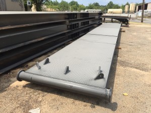
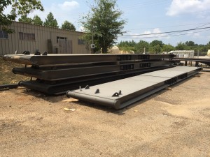
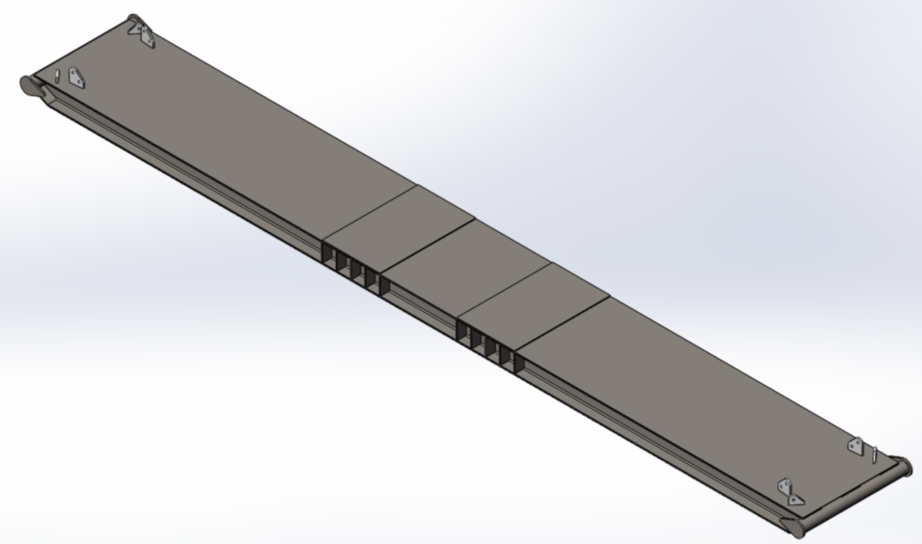
With reference to FIGS. 2 and 3, the base beam 12 includes a main beam 40 that extends along a longitudinal axis A-A from a first end 42 ato a second, opposite end 42 b.The main beam 40 further includes a front side 44, a back side 46, a top 48 and a bottom (not visible in FIGS. 2-3). The bottom is substantially planar to allow the main beam 40 to lay flat on the ground. In the illustrated example, the main beam 40 is generally rectangular in shape, although other shapes could be used.
The main beam 40 further includes a substantially planar central section 50 approximately midway between the first and second ends 42 a, 42 bthereof. As discussed further below with respect to FIGS. 4-5, in use the central section 50 supports the base of the derrick structure 18. Therefore, if considered necessary to support the derrick structure, the central section 50 of the main beam can be reinforced between the top 48 and the bottom, for example by employing internal reinforcing members disposed within the main beam 40 at the central section 50.
Further, first and second swing or stabilizer arms 52 a, 52 bare pivotally attached to the main beam 40. In the embodiment illustrated in FIGS. 2 and 3, the swing arms 52 a, 52 bare pivotally attached to the main beam adjacent to the first and second ends 42 a, 42 b,respectively. The swing arms are pivotable relative to the main beam 40 between a retracted position (shown in FIG. 2) where the first and second swing arms are generally parallel to the main beam and a fully extended or deployed position (shown in FIG. 3) where the first and second swing arms are not parallel to the main beam.
In an alternative embodiment, the stabilizer arms can be initially separate from the main beam 40 and then attached to the main beam in the extended or deployed position for use. In this embodiment, the stabilizer arms need not be pivotally attached since the arms are attached for use and detached (or not detached) during transport.
In the illustrated embodiment, when fully deployed, the swing arms 52 a, 52 bextend from the front side 44 of the main beam and are disposed at generally right angles to the longitudinal axis A-A. As shown in FIG. 2, each of the first and second swing arms has a length L, and the combined length of the first and second swing arms 52 a, 52 bcan be less than the longitudinal length of the main beam to permit the swing arms to completely fold to the retracted position parallel to the axis A-A. However, as discussed further below, other configurations of the swing arms are possible.
Each swing arm 52 a, 52 bincludes a first swing arm end 54 that is pivotally attached to the main beam, and a second swing arm end 56. A stabilizer pad 58 is connected to the second swing arm end 56 of each swing arm. Each stabilizer pad 58 is adjustable in height to allow leveling of the swing arms and the base beam on uneven ground.
The base beam 12 is constructed primarily of a metal material such as steel. The main beam 40 between the top 48 and bottom is generally hollow. However, if additional weight for the base beam 12 is required, weights that are initially separate from the main beam can be disposed on the main beam adjacent to each of the ends 42 a, 42 b.In one embodiment, concrete can be poured into the hollow interior of the main beam adjacent to the ends 42 a, 42 bto increase the weight of the base beam. In another embodiment, removable weights can be placed on top of the main beam adjacent to the ends thereof. However, any technique for adding weight to the base beam 12 to increase the weight of the beam can be used.
The base beam 12 further includes a plurality of guy attachment points to permit attachment to the guys 30. The guy attachment points can be provided at locations that one determines to be suitable for adequately guying the derrick structure 18. In the embodiment illustrated in FIGS. 2 and 3, there is at least one guy attachment point 60 on each of the first and second swing arms, for example adjacent to the second ends 56. In addition, there can be a plurality of guy attachment points 62 on the main beam 40, for example adjacent to the ends 42 a, 42 b.The guy attachment points 60, 62 can be, for example, flanges that are attached to the base beam 12 and that include a hole to permit attachment of one end of the guys. The guys 30 (as well as the guys 28) can be wires or any structure suitable for use as guys.
Other configurations of the base beam are possible. For example, FIG. 10 illustrates a base beam 212 with a main beam 240 and a pair of swing arms 252 a, 252 bpivotally attached to the main beam 240 for pivoting movement between a retracted position (not shown) where the first and second swing arms are generally parallel to the main beam and a fully extended or deployed position (shown in FIG. 10) where the first and second swing arms are not parallel to the main beam. In this embodiment, the swing arms are pivotally attached to the main beam 240 so that the first and second arms 252 a, 252 bextend from a back side of the main beam when in the fully extended position in a direction generally toward the front end of the rig 14 and parallel to the rig.
FIG. 11 illustrates a base beam 312 with a main beam 340 and two pairs of swing arms 352 a, 352 b, 352 c, 352 dpivotally attached to the main beam 340 for pivoting movement between a retracted position (not shown) where the swing arms are generally parallel to the main beam and a fully extended or deployed position (shown in FIG. 11) where the swing arms are not parallel to the main beam. In this embodiment, the swing arms are pivotally attached to the main beam 340 so that the swing arms 352 a, 352 bextend from a front side of the main beam similar to FIGS. 2-3, while the swings arms 352 c, 352 dextend from the back side of the main beam similar to FIG. 10.
FIGS. 12A and 12B illustrate a base beam 412 with a main beam 440 and two pairs of swing arms 452 a, 452 b, 452 c, 452 dpivotally attached to the main beam 440 for pivoting movement between a retracted position (shown in FIG. 12B) where the swing arms are generally parallel to the main beam and a fully extended or deployed position (shown in FIG. 12A) where the swing arms are not parallel to the main beam. In this embodiment, the swing arms are pivotally attached to the main beam 440 so they extend from the front and back sides of the main beam similar to FIG. 11. In addition, each of the swing arms 452 a, 452 bincludes a first section 454 that is pivotally attached to the main beam and a second section 456 that is pivotally attached to the first section. Constructing the arms 452 a, 452 bwith two sections allows the two sections 454, 456 to fold together, for example one above the other as shown in FIG. 12B, which allows the length of the arms to be increased, while allowing the arm sections 454, 456 to fold to the retracted position.
FIG. 14 illustrate a base beam 512 with a main beam 540 and a pair of swing arms 552 a, 552 bpivotally attached to the main beam 540 for pivoting movement between a retracted position (not shown) where the swing arms are generally parallel to the main beam and a fully extended or deployed position (shown in FIG. 14) where the swing arms are not parallel to the main beam. In this embodiment, the swing arms 552 a, 552 bare pivotally attached to the main beam 540 away from the ends of the beam 540 and more toward the center of the main beam. In addition, the swing arms do not extend at right angles to the main beam as in the other embodiments. Instead, the swing arms 552 a, 552 bare disposed at acute angles a relative to the longitudinal axis of the main beam.
Returning now to FIGS. 1-3 together with FIGS. 4-5, in use, the base beam is transported to a position adjacent to the well head 16 and arranged on the ground. The swing arms are then deployed from the retracted position, which is used during transport of the base beam, to the fully deployed position. If necessary, the stabilizer pads 58 are adjusted in height to level the swing arms and the main beam. The self-propelled derrick rig 14 is then backed up to a position adjacent to the base beam as shown in FIG. 4. During this time, the derrick structure 18 is likely at its lowered or transport position as shown in FIG. 4, although in some circumstances the derrick structure could already be raised or partially raised. If the derrick structure is not raised, the derrick structure is raised to the raised position shown in FIG. 1.
With reference to FIG. 5, once the derrick structure 18 is raised, a base end 70 of the derrick structure is attached to the base beam 12. In particular, one side of the base end 70 is pivotally connected to the rig platform 20 by pivots 72. The other side of the base end is provided with a pair of height adjustable stabilizer pads 74. Metal plates 76 are laid on the top 48 of the main beam at the central section 50, and the pads 74 rest on the plates 74. The base end 70 is fixed to the main beam by one or more fixation members 78. In one embodiment, four fixation members 78 can be used, each of which attaches at one end to the base end 70 of the derrick structure 18 and attach at opposite ends thereof to mounting fixtures 80 that are disposed adjacent to the front side and the back side respectively of the main beam adjacent to, and on opposite sides of, the central section 50. In the illustrated embodiment, the fixation members 78 comprise shackles, although any type of fixation members that can adequately attach the base end of the derrick structure to the main beam can be used.
In addition, as shown in FIG. 1, the guys 28 are then attached between the derrick structure and the remainder of the rig, and the guys 30 are attached between the derrick structure and the base beam. FIG. 1 illustrates the derrick structure 18 as including a rig floor 82 and a tubing or racking board 84 both of which are conventional structures on workover rigs. The guys 28 are illustrated as generally extending from the top of the derrick structure to other points on the rig. Some of the guys 30 extend from the base beam to the top of the derrick structure, while some of the guys 30 extend from the base beam to the tubing board 84 and from the tubing board to the top of the derrick structure. However, the exact arrangement and number of the guys 28, 30 can vary based on a number of factors, such as the expected loading conditions on the derrick structure and the rig. Therefore, the guy arrangement illustrated in FIG. 1 is exemplary only and can vary from the illustrated arrangement both in the number of guys 28, 30 used and their locations.
Under some loading conditions, for example when the derrick structure is pulling at or near capacity, the front end of the rig 14 may want to come off the ground. To prevent such an occurrence, an optional counterweight assembly 90 can be used that is connected to the front end of the rig 14 to weigh down the front of the rig. The assembly 90 can simply connect to the front of the rig by resting on some portion of the front. Alternatively, the assembly 90 can be connected to the rig by removably attaching the assembly to the rig, for example by pinning or bolting the assembly to the rig. Any form of connection can be used as long as the assembly 90 increases the weight of the front of the rig.
With reference to FIGS. 6-8, the counterweight assembly 90 can include a sled 92 that is designed to connect to the rig 14 and carry separate weights 94 that can be added and removed from the sled 92 to alter the amount of weight carried by the sled.
The sled 92 is a generally rectangular structure that includes a base 96, reinforcing members 98 at each side end of the base, a front side 100 and a rear side 102. The rear side 102 of the sled 92 includes a plurality of vertical beams 104 connected at base ends thereof to the base 96 and at upper ends thereof to a horizontal beam 106. As best seen in FIG. 8, the horizontal beam 106 and/or the beams 104 can be connected to a block, for example of wood, that rests on a ledge at the front of the rig. Thus, the assembly 90 weights down the front end of the rig.
If there is concern that the assembly could move, the assembly could be removably attached to the rig. For example, with reference to FIG. 16, the attachment mechanism can comprise flanges 116 that are fixed to the beam 106 and/or the beams 104, with corresponding flanges 118 on the front of the rig that align with the flanges on the sled. Pins or bolts 119 can then extend through holes in the aligned flanges to attach the sled to the rig.
Each weight 94 is individually separable from the other weights 94 and each weight is individually removable from the sled 92. The weights 94 are generally rectangular in shape and resemble plates. The sled can be designed to hold any number of weights, based in part on how much counterweight one may need.
To aid in mounting, removal and transport of the sled 92, at least two forklift pockets 110 are formed in the base 96. The forklift pockets 110 permit a forklift to lift and transport the sled 92. Similarly, each of the weights 94 includes at least two forklift pockets 112 formed therein. The forklift pockets 112 permit a forklift to lift and transport each of the individual weights 94. Instead of forklift pockets, any structure that performs a function similar to the forklift pockets can be used.
With reference to FIG. 9, the shape of the sled 92 is such that the sled 92 together with any weights held thereon can be disposed on the base beam 12 during transport of the base beam and the counterweight assembly. This minimizes the space taken up during transport.
With reference to FIG. 13, an embodiment is illustrated that uses two base beams. One base beam 120 is substantially similar to the base beam 12. Alternatively, the base beam 120 could be similar to the base beams 212, 312, 412, or 512. A second base beam 122 is disposed underneath the rig 14, for example underneath jacks or outriggers that are provided on the rig 14. The construction and use of jacks or outriggers on rigs is well known in the art. In this embodiment, guys 124 extend from the derrick structure 18 and are connected to the ends of the second base beam 122 to help support the derrick structure.
FIG. 15 shows another embodiment that uses two base beams, including one base beam 130 that is substantially similar to the base beam 12. In this embodiment, a second base beam 132 is disposed underneath the rig 14 at a location that is further forward than the second base beam 122 in FIG. 13. For example, the second base beam 132 can be disposed underneath jacks disposed under the driver"s cab 22, and guys 134 extend from the derrick structure 18 and are connected to the ends of the base beam 132 to help support the derrick structure.
The second base beams 122, 132 illustrated in FIGS. 13-15 are depicted as not including swing arms. However, the second base beams 122, 132 could be configured to have swing arms similar to those discussed above.
a longitudinally extending metal main beam having first and second opposite ends, a front side, a back side, a top and a bottom, the bottom is substantially planar;
the main beam includes a central section approximately midway between the first and second ends thereof, the central section is reinforced between the top and the bottom, and the top of the central section is substantially planar;
first and second swing arms pivotally attached to the main beam, the swing arms are pivotable relative to the main beam between a retracted position where the first and second swing arms are generally parallel to the main beam and a fully extended position where the first and second swing arms are not parallel to the main beam; and
3. A base beam as recited in claim 1, each of the first and second swing arms includes a first swing arm end that is pivotally attached to the main beam, and a second swing arm end; and the guy wire attachment point of each of the first and second swing arms is located adjacent to the second swing arm end.
4. A base beam as recited in claim 1, further comprising weights, separate from the material forming the main beam, disposed on the main beam adjacent to each of the first and second opposite ends.
5. A base beam as recited in claim 3, further comprising a stabilizer pad connected to each swing arm adjacent to the second swing arm end; each stabilizer pad is adjustable in height.
7. A base beam as recited in claim 1, wherein the first and second swing arms are pivotally attached to the main beam so that the first and second arms extend from the front side of the main beam when in the fully extended position.
8. A base beam as recited in claim 1, wherein the first and second swing arms are pivotally attached to the main beam so that the first and second arms extend from the back side of the main beam when in the fully extended position.
9. A base beam as recited in claim 7, further comprising third and fourth swing arms pivotally attached to the main beam, the third and fourth swing arms are pivotable relative to the main beam between a retracted position where the third and fourth swing arms are generally parallel to the main beam and a fully extended position where the third and fourth swing arms are not parallel to the main beam, and the third and fourth swing arms extend from the back side of the main beam when in the fully extended position.
10. A base beam as recited in claim 1, wherein each of the first and second swing arms includes a first section that is pivotally attached to the main beam and a second section that is pivotally attached to the first section.
11. A base beam as recited in claim 1, further comprising first and second mounting fixtures disposed adjacent to the front side and the back side respectively of the main beam adjacent to, and on opposite sides of, the central section.
12. A base beam as recited in claim 1, wherein each of the first and second swing arms has a length, and the combined length of the first and second swing arms is less than the longitudinal length of the main beam.
a longitudinally extending metal main beam having first and second opposite ends, a front side, a back side, a top and a bottom, the bottom is substantially planar; the main beam includes a central section approximately midway between the first and second ends thereof, the central section is reinforced between the top and the bottom, and the top of the central section is substantially planar;
first and second stabilizer arms attached to the main beam, the stabilizer arms extend from the main beam at an angle to a longitudinal axis of the main beam; and
15. A base beam as recited in claim 13, each of the first and second stabilizer arms includes a first stabilizer arm end that is attached to the main beam, and a second stabilizer arm end; and the guy wire attachment point of each of the first and second stabilizer arms is located adjacent to the second stabilizer arm end.
16. A base beam as recited in claim 13, further comprising weights, separate from the material forming the main beam, disposed on the main beam adjacent to each of the first and second opposite ends.
19. A base beam as recited in claim 17, further comprising third and fourth stabilizer arms attached to the main beam, and the third and fourth stabilizer arms extend from the back side of the main beam.
Support arrangement including base support means and elevatable support means to transport a drawworks and drilling mast supported thereon and for positioning at a drilling location
This website is using a security service to protect itself from online attacks. The action you just performed triggered the security solution. There are several actions that could trigger this block including submitting a certain word or phrase, a SQL command or malformed data.
SCOPE: To provide a representative basis for determining the availability, capability, dependability, reliability of Stability Systems on Land Based Work-Over Rigs and the recommended practices and procedures for their safe use.
The rig location area may grade away from the well bore along centerline II at a maximum drop of 1:20. The cross grades, parallel to centerline I, should be level. The area shall provide a minimum bearing capacity of 6000 psf.
The flat plate anchor is stamped from metal plate then folded into a reduced profile for insertion into the ground. The flukes are expanded into undisturbed soil, again by tamping or impact, to provide the holding power for this type of anchor. A base plate supports the extended flukes providing added strength and stability.
The "Well Head" is located at the center of the Chart. This will be considered the base reference point for positioning of the guy anchors. The holding capacity of the anchors will then be determined by the zone in which they are located. ie: A, B, C, or D.
The near parallel baseline of Zone "D" to the cross lines NS and EW is 25 feet. (see Northwest and Southeast Quadrants). The far baseline of Zone "D" to the cross lines is 35 feet. (see Northwest and Southeast Quadrants). The vertical distance from the cross lines to the end of the base line is 60 feet and 85 feet to the end of the far line. The area located within this geometrically angled rectangle, within each quadrant, is the area comprising Zone "D".
Using the chart: An anchor in Zone "A" located a horizontal distance of 70 feet from the "Well Head" would require an anchor of what minimum holding capacity? On the chart move along the horizontal legend from left to right until you reach 70 feet. At this juncture proceed vertical until you intersect the curved line for Zone "A", now follow the intersecting horizontal line, left toward the vertical legend. We have now determined that the minimum holding capacity for the anchor, at this precise location, is 20,000 pounds.
Standing at the "Well Head", with the well bore immediately to your back, proceed North (in direction monkey board is facing) 24 paces. (The pace length is not as important as the numerical relationship of the units and the consistency of the unit length. The method will work with any unit of length as long as the same unit is used throughout.) Place a stake or other marker at this location (Bench Reference). Turn West 90 degrees and proceed forward 10 paces. At this location turn your body so that the front portion of your anatomy is approximately parallel to the radial of the guy anchor. If the northwest guy anchor is forward of your right shoulder and the southeast guy anchor is aft to the rear of your left shoulder, it can then be presumed that the radial angles are within acceptable parameters. Repeat the procedure from the bench reference, this time to the east, proceed ten paces. In this orientation the northeast anchor should be forward of the left shoulder and the southwest anchor should be aft of the right shoulder.
In keeping with the concept, which embraces the acceptance of new and innovative approaches, that are based on sound engineering principals, the following alternative, recommended installation guideline, is presented.
A survey of 13 drilling contractors operation 193 drilling rigs in northern Canada and Alaska indicated that there is a wide range of experience and operating practices under extremely low temperature conditions. While there is very little precise information available, there have been a sizeable number of failures in portable masts while in the lowering or raising process in winter. Thus the exposure to low temperature failures focuses on mast lowering and raising operations. Based on reports, however, this operation has been accomplished successfully in temperatures as low as -50 degrees F. While the risk may be considerably greater because of the change in physical characteristics of steel at low temperatures, operators may carry on "normal" operations even at extremely low temperatures. This may be accomplished by a program of closely controlled inspection procedures and careful handling and operation. This should reduce damage and impact loading during raising and lowering operations. At the present, there seems to be no widely accepted or soundly supported basis for establishing a critical temperature for limiting the use of these oilfield structures. Experience in the operation of trucks and other heavy equipment exposed to impact forces indicates that -40 degrees F may be the threshold of the temperature range at which the risk of structural failure may increase rapidly. Precautionary measures should be more rigidly practiced at this point. The following recommended practices are included for reference:
* Make use of any practical, available means to warm sections of the mast, such as using high pressure steam to heat the points of attachment between the mast and its base; also timber bonfires, and the like.
If maintained to these tolerances the sags will indicate a pretension of 1000 pounds for crown to ground guywires and 500 pounds for tubing board guywires. this is based on the use of 5/8 inch, 6x19, or 6x37 class, regular lay, ips, IWRC wire rope, installed according to the rigging guidelines set forth in chart depicted in Figure 5-5
The drawing on the following page, Figure 5-4, (SAME AS FIGURE 4-4) is another illustration of the continuing evolution of Rig Stability System engineering and design. It represents the latest API thinking relative to planing and preparing a Rig Stability System.
CAUTION: SOLE EMPHASIS SHOULD NOT BE PLACED ON PULL TESTING OR ALTERNATIVES TO PULL TESTING AS THIS MEASURES ONLY ONE COMPONENT OF THE RIG STABILITY SYSTEM.
The rig contractor should be responsible for the following: a. Insuring that anchor capacities are verified and that anchor spacing and capacity is suitable for the mast guying pattern and anticipated loading.
b. Records of pull testing or records of other methods used to verify temporary anchor capacity should be retained by the rig contractor until the job is complete and the guy wires have been removed from the anchors. The records should indicate the capacity of each anchor, the date of verification, name and phone number of the party responsible for verification, and the soil condition at the time of verification.
OUT OF AN ABUNDANCE OF CAUTION IT IS EXTREMELY IMPORTANT TO POINT OUT THAT THE PREVENTION OF RIG UPSET IS DIRECTLY DEPENDENT ON THE TOTAL INTEGRITY OF THE RIG STABILIZATION SYSTEM. THE SYSTEM INCLUDES ALL OF ITS COMPONENTS AND IS ONLY AS SOUND AS ITS WEAKEST MEMBER.
Our research has concluded, that the latest State-of-the-Art in RIG STABILIZATION is to be found in the pending American Petroleum Institute, Recommended Practice for MAINTENANCE and USE of DRILLING and WELL SERVICING STRUCTURES.

The claimed invention relates generally to well drilling and servicing equipment, and more specifically to portable rigs for handling pipe strings when making up and disconnecting long strings of pipe used in a bore hole during operations that are carried out in the exploration and production of petroleum and other fluids and minerals from substantial depths below the earth"s surface.
When such service operations become necessary, a portable installation called a workover rig is brought to the well site and set up. Generally, these rigs consist of a derrick or mast which supports pulleys or block and tackle arrangements that are operable to pull the pipe string from the well. These prior art workover rigs are usually heavy and difficult to erect and further often have the limited operational capability of only being able to hoist or pull pipe from a well without the capability of snubbing or pushing pipe back into the well. Since these conventional workover rigs cannot develop a downward force to push a string of pipe into the well, in such operations the well must necessarily always be under control or "dead", as is known in the art. This may require a preparatory operation of injecting a suitable substance such as mud or "kill" fluid into the well to maintain sufficient column weight of fluid to resist the pressure within the well which is tending to force the tubing out. However, it is usually desirable to carry out the workover operations without resorting to the injection of "kill" fluid into the well since the well may be lost if the formation is damaged because of the presence of the workover "kill" fluid. In such "killing" workover operations, there is a very high risk that the productivity of the subsurface formation may decline so severely after killing the well that the well must be abandoned.
An overriding concern in the construction of workover rigs is to get the necessary equipment into and out of the well as rapidly and safely as is economically possible. This concern has led to the development of a portable well service rig having a transportable mast or derrick. Before the invention of the first portable well service unit, it was necessary to leave the drilling derrick in place over the well for use in future well service operations. The portable well service rig eliminated the need for a permanent derrick and thus materially reduced overall well service costs. The early portable rigs, however, were unloaded in a heap and later sorted out, and then assembled without any definite plans therefore consuming a substantial amount of time in rigging up. Even when unitized and transported on pallets, a significant amount of time was required for transporting, rigging up and dismantling the palletized equipment. In the palletized approach, the field assembly and erection of the mast, mast support structure and reeving of the hoist cable caused expensive but unavoidable delays. Therefore recent improvements to conventional portable workover rigs have focused on changes which simplify the operations of transporting, rigging up and dismantling.
One of the problems associated with the development of the portable workover rig is that of providing sufficient working space below the mast floor while limiting the mast and its supporting base to dimensions which permit its transportation across public highways. A working space must be provided below the mast floor in order that the mast can be supported vertically above and engage well head equipment which may extend as much as eight to ten feet above the elevation of the rig platform deck. The minimum height of the mast is determined primarily by the length of the sections of pipe string added to or removed from the pipe already in the well bore. However, if the mast is so high that its length and height clearance when in a horizontal position on the workover rig exceeds the limits allowed by the state, the mast must be at least partially disassembled or must be telescoped. Most wells have tubing sections which are in the range of thirty-six to forty feet long, so that the construction of a transportable mast assembly having a stroke for accomodating the removal or insertion of such tubing sections poses no problem insofar as complying with state highway regulations.
As mentioned above, the conventional practice has been to provide a mast having telescoping sections or having sections which must be separately assembled and erected on site. To provide ample clearance for the well head equipment, the mast floor has been elevated above the ground level by placing it on a mast substructure carried by the rig base platform. This substructure is normally fabricated of heavy structural steel in a massive weldment which must be separately transported. The loads it must bear are greater than those born by the mast, since the substructure must support not only the weight of the derrick with its pipe string load, but other loads, such as the rotary table and draw works as well. However, the length and height of the separate mast support base when combined with the reclining mast may in some cases exceed highway limits, so that separate transportation, field assembly and erection are required. Most conventional rigs provide separate support base and mast sections which may be unbolted and separately transported to provide the short lengths allowed for highway travel. However, additional rigging up and tear down time is required for such arrangements.
Other important considerations involved in the construction of portable workover rigs are the strength and stability of the mast. The mast must be constructed to safely carry all loads which will ever be used in the well over which it is placed. This is the collapse resistance caused by vertical loading, or the dead load capacity of the mast. The largest dead load which will be imposed on the derrick will normally be the heaviest string of production tubing run in the well. However, this heaviest string of tubing will not be the greatest strain placed on the mast. The maximum vertical load which will ever be imposed on the mast will probably be the result of pulling on equipment, such as drill pipe or casing, that has become stuck in the hole. Therefore it must be considered that, sometime during the useful life of the mast, severe vertical strain will be placed on it because the equipment has become stuck in the hole. Therefore the mast and its intermediate support platform must be constructed to withstand and react loads which will exceed the capacity of the hoist line which will be used on the rig.
The mast must be also designed to withstand the maximum wind loads to which it will be subjected. The horizontal force of the wind acting on the mast and production tubing is usually counteracted by using from one to three guy wires along each leg of the mast which are attached to "dead man" anchors located some distance from the mast. A "dead man" anchor is made from a short length of large pipe, a concrete block, or a short section of timber, which is buried in the ground to provide an anchor for the guy wire. A substantial amount of time and labor is expended in setting up the "dead man" support lines. Additionally, when carrying out workover operations off shore, there is no practical way to anchor the guy lines. A suitable structural alternative for the guy wire supports is necessary for reacting the wind loads, and the snubbing forces must also be reacted in order to drive production tubing into an offshore well against the downhole pressures which may be encountered. Therefore there is a continuing interest in improving the design of support substructure for free-standing masts which do not require guy wires for support.
As a result of the many improvements to portable workover rigs, such vehicles now transport practically all the necessary servicing equipment directly to the field locations and when servicing has been completed, remove the necessary equipment to another well in need of service in the same field or in a different field miles away. Thus the equipment necessary to service a number of wells each having different service requirements has been greatly reduced, and consequently the labor and cost, as well as the amount of equipment has correspondingly dropped. However, there still remains considerable interest in the provision of more efficient and simplified machines in order that the job of well servicing in general may be carried out efficiently and at reasonable cost.
It is, therefore, the principal object of the present invention to provide an improved general purpose workover rig having a unitized configuration which is transportable across public highways and which can be easily rigged up and dismantled in the field.
An important object of the invention is the provision of a mast assembly which is transportable on a base platform having a mast and a mast support substructure which can be separately collapsed for transport in a low profile, reclining position over the base platform to comply with the length and height limitations established for public highways, and which are erectable to an elevated operating position overlying well head equipment.
Yet another object of the invention is the provision of a transportable mast assembly having a base support substructure for supporting the mast in freestanding relation for withstanding wind loading without the use of dead man anchor lines.
Still another object of the invention is the provision of a workover rig having a mast, a mast support substructure, and draw works in which the static load of the draw works is supported by a portable base platform member rather than by being supported by the intermediate mast support substructure.
Another object of the invention is the provision of an erectable mast support substructure which cooperates with a portable base platform for stabilizing a free-standing mast erected on the support substructure and reacting vertically directed snubbing forces without the use of dead man anchor lines.
Yet another object of the invention is the provision of a workover rig having draw works carried by a portable platform and a mast and mast support substructure which are separately movable from a reclining transport position to an erect operating position wherein erection and retraction of the mast and mast support assembly can be carried out without disturbing cable reeving on the mast or on the draw works.
An important object of the present invention is the provision of draw works for a workover rig which can be carried in a reclining position on a portable rig platform and which is operably connected to develop driving forces required for either hoisting or snubbing operations.
Still another object of the invention is the provision of a portable workover rig having a mast and mast support substructure which are separately movable from a reclining transport position over a portable base platform to an erect workover position overlying well head equipment lying either above or below the elevation of the portable base platform.
A further object of the invention is the provision of a carriage assembly for a cantilever mast support substructure for maintaining the cantilever mast support substructure in parallel alignment with the base platform throughout the range of movement from a reclining transport position to an erect operating position.
Yet another object of the invention is the provision of a base support substructure for an erectable mast and a carriage assembly for moving the base support substructure from a reclining transport position over a portable base platform to an erect workover position, the carriage assembly cooperatively coupled to the base platform for stabilizing the erectable mast in free-standing relation on the mast support substructure and for transmitting mast load reaction forces through the portable base platform.
Another object of the invention is the provision of a workover rig having an erectable mast supported on a cantilever support substructure which is movable from a reclining transport position overlying a portable base platform to an elevated position of use wherein the cantilever support base is extended beyond the portable base platform for carrying out workover operations.
Still another object of the invention is the provision of a vertically adjustable stack assembly for accomodating the varying elevations of existing well head flange connections and which further serves to transfer the weight of a mast from an intermediate support structure to the well casing and for simultaneously anchoring a portable base platform to the well head casing, thereby further stabilizing the mast support substructure.
The foregoing objects are achieved by a workover rig which is mounted on a portable base platform such as a skid or the bed of a trailer vehicle, and which features a collapsible mast assembly which is movable from a reclining transport position to an erect elevated position of use. The mast assembly is supported for freestanding operation by a carriage assembly including a cantilever substructure support base mounted on the rig support platform for pivotable movement from the reclining transport position to an elevated position of use. The carriage assembly includes lift arms coupled in parallel relation intermediate the cantilever support structure and the rig support platform, thereby defining a parallelogram throughout the range of movement of the mast support assembly for maintaining the cantilever support base in parallel alignment with the base platform. According to this arrangement, the mast and the carriage assembly are separately collapsible for transport in a low profile, reclining position over the base platform to comply with the length and height limitations established for public highways. The mast and the carriage assembly are separately erectable to an elevated operating position overlying well head equipment which may be disposed at an elevation either above or below the elevation of the portable base platform. The mast is connected in hinged engagement with the carriage assembly, and both the carriage assembly and the mast are separately driven from the transport position to the erect operating position by linear hydraulic actuators. The linear hydraulic actuators in combination with the carriage assembly serve to stabilize the mast for free-standing operation and transmit mast load reaction forces through the portable base platform. An important feature of this arrangement is the cantilever support substructure which is extended to an elevated operating position beyond the portable base platform for carrying out workover operations adjacent elevated well head equipment. A further advantage of this arrangement is that the mast, mast support substructure, and draw works can be carried in a collapsed, low profile transport position and both erection and retraction of the mast and mast support assembly can be carried out without disturbing the cable reeving on the mast and draw works.
According to an important aspect of the invention, the workover rig is provided with a mast, a mast support substructure, and draw works in which the static load of the draw works is supported by a portable base platform member rather than being supported by the intermediate mast support substructure. In this arrangement, the draw works includes a linear hydraulic actuator having rod and housing elements in which one of the elements is anchored to the base platform with the other element being mounted for movement along the base platform through a stroke pathway which extends transversely with respect to the mast. The traveling sheaves are cooperatively reeved with hoist and snub cables for developing driving forces required for either hoisting or snubbing operations. The advantage of this arrangement is that the intermediate mast support substructure must support only the mast in an erect operating position with the substantial weight of the draw works being supported by the portable base platform. This arrangement permits the mast support substructure to be easily movable from the reclining, low profile transport position to the elevated workover position without the burden of the draw works. Hoisting and snubbing operations are carried out by the draw works which includes a linear hydraulic actuator carried on the base platform, a load engaging traveling block supported for vertical movement along the mast by hoist and snub cables, and by traveling sheaves carried by the actuator through a stroke pathway which is oriented transversely with respect to the mast. In this arrangement the load engaging traveling block is driven upwardly or downwardly along the mast in response to extension and retraction of the rod and housing elements of the hydraulic actuator.
In yet another important embodiment of the invention, a vertically adjustable stack assembly is provided for accomodating the existing elevation of well head flange connections. The vertically adjustable stack assembly includes an adjustable support column assembly anchoring the rig platform to the well head casing, and an adjustable support column assembly interposed between the well head casing and the mast for transferring the weight of the mast from the intermediate mast support structure to the well casing. The vertically adjustable stack assembly simultaneously anchors the portable base platform to the well head casing, thereby stabilizing the mast support substructure, while relieving the burden of the mast from the intermediate mast support substructure. This arrangement helps stabilize the mast for free-standing operation on the mast support substructure and for transmitting mast load reaction forces through the portable base platform, thereby eliminating the need of dead man anchor lines which would otherwise be required for stabilizing the mast and for reacting dynamic mast loads.
Finally, the portable workover rig of the invention is adapted to perform drilling operations by the combination of a vertically yieldable stab assembly which interconnects a powered drill sub with a traveling block for permitting vertical displacement of the powered drill sub during make-up and break-out operations while simultaneously reacting torque forces which arise in response to rotary forces applied to the drill string. The vertically yieldable stab assembly includes upstanding stab receptacles anchored to the top side of the traveling block and stab elements downwardly depending from the under side of the powered drill assembly for engagement with the stab receptacles. Each stab element is supported for vertical reciprocal movement between retracted and extended positions, and each stab element is yieldably biased to the fully extended position, thereby permitting vertical displacement of the power sub relative to the traveling block during the make-up and break-out operations while reacting torque forces which are produced by operation of the powered drill sub.
FIG. 3 is a top plan view of the workover rig of FIG. 1 with the mast and carriage assembly removed which illustrates the layout of the draw works and related equipment on the deck of a portable rig support platform;
FIG. 7 is a side elevational view of a skid mounted workover rig having draw works and an erectable mast constructed according to the teachings of the present invention;
FIG. 10 is a perspective view which illustrates the arrangement of sheaves and reeving of cables for conducting snubbing operations on the workover rig shown in FIG. 1;
FIG. 11 is a perspective view which illustrates the arrangement of sheaves and reeving of cables for conducting hoist operations on the workover rig shown in FIG. 1;
FIG. 16 is a front elevation view of the completed vertically adjustable stack assembly shown interconnecting the mast support substructure and the rig support platform with the flanged connector of a well head assembly;
Referring now to the drawings, and more particularly to FIGS. 1-4, a workover rig 10 is shown having a transportable mast assembly 12 and draw works 14 supported on a portable trailer platform 16. The trailer platform 16 includes the usual longitudinal side frame rails 18, 20 which supports forward and rear decks 22, 24, respectively. The side rails 18, 20 are interconnected by the usual structural members, including a tailboard 26. The trailer platform 16 includes a fifth wheel connection 28 for attachment to a tractor, and rear wheels 30 supported by shock assemblies and leaf springs in the usual manner. Outrigger jacks or props 32 support the side frame rails 18, 20 to prevent tilting or overturning of the rig during operation and also for maintaining the orientation of the trailer platform 16 once it has been set up. The jacks 32 are preferably hydraulically actuated and are controlled from a central station so that the trailer platform 16 can be aligned in parallel with the ground or inclined in a tilted position for workover of slant wells. Each jack 32 is equipped with a stabilizer pad 34 for engaging a mud sill (not shown) so that the trailer load can be more evenly distributed. Slung underneath the side frame rails 18, 20 are tool boxes 36 and a spare tire 38. Anchored top side on the forward deck 22 is power unit 40 which develops the main hydraulic power for the draw works 14 and includes hydraulic pumps driven by a diesel engine. The power unit is coupled to a hydraulic reservoir 42 so that as the required pressure in the system exceeds predetermined levels, one or another pump automatically unloads into the reservoir 42 and all engine horse power is then diverted for driving the alternate pump(s). Immediately forward of the power unit 40 are a pair of fuel tanks 44, and overlying the fifth wheel connection 28 is a hose basket 46. Overlying the fuel tanks is an upstanding stop bar 47 for engaging the mast assembly and supporting it in spaced relation with the forward deck overlying the power unit and fuel tanks when the transportable mast assembly 12 is disposed in its reclining transport position, as illustrated in FIGS. 1 and 2. Also anchored to the trailer platform 16 intermediate the forward and rear decks is a guide tube 48 which is straddled by the hydraulic reservoir 42 for receiving the movable actuator element of the draw works 14 as will be discussed in greater detail below.
Referring again to FIGS. 1-4, the transportable mast assembly 12 comprises generally an elongated mast 50 pivotally mounted on a mast support substructure 52 which is in turn pivotally mounted on a mast carriage assembly 54 which is mounted for pivotal movement from a transport position shown in FIG. 2 to an elevated position of use shown in FIG. 1. The mast 50 is formed by two upstanding mast sections 50A, 50B which are laterally spaced to define a vertical load transport zone 56 through which a traveling block 58 is transported during pipe running operations. The upper ends of the mast sections 50A, 50B are structurally interconnected by a crown block 60 which improves the mechanical stability of the mast and which also serves to support crown block sheaves in a manner to be disclosed hereinafter. Each mast section 50A, 50B is defined by four leg members 62A, 62B, 62C and 62D, and 64A-D, respectively. The leg members are generally arranged at the corners of a square with the forward leg portions terminating in a clevis which receives a hinge pin 66 which pivotally secures the forward legs to the mast support substructure 52. Each mast section 50A, 50B is provided with girt members 68 and brace members 70 which are structurally interconnected with the leg members to insure rigidity of each mast section. A clevis 72 is anchored on opposite sides of the mast support substructure 52 for anchoring the rear legs 62B, 64B of the mast when it has been erected to the upright position.
The mast support substructure is characterized by a cantilever support base 74 which is pivotally coupled to the mast carriage assembly 54. The cantilever support base 74 serves as an intermediate mast support substructure for supporting the upstanding mast 50 in an elevated position beyond the tailboard 26 and above well head equipment. The cantilever support base 74 assumes the form of a rectangular frame having a forward section 74A for pivotal engagement with the mast carriage assembly 74 and a rear portion 74B which forms the substructure support for the mast 50. A slip assembly 54 is anchored onto the cantilever support base for assisting the traveling block 58 during pipe gripping operations.
The mast carriage assembly 54 includes forward and a rear lift arms 76A, 76B, respectively, pivotally coupled in clevis connections intermediate the cantilever support base 74A and the rear deck 24 on laterally opposite sides of the draw works 14. The lift arms are all the same length and are spaced in parallel with each other whereby the combination of each pair of lift arms with the cantilever support base and the rear deck defines a parallelogram for maintaining the mast support substructure 52 in parallel alignment with the trailer platform 16 throughout the range of movement of the mast support substructure 52 from the reclining transport position to the elevated position of use. The mast support substructure 52 is extended and retracted between the reclining transport position and the elevated position of use by a pair of double acting, telescoping hydraulic actuators 78 having housing and rod elements pivotally coupled to clevis connections carried on the forward cantilever support base portion 74A and the rear deck 24 on laterally opposite sides of the draw works 14. The mast 50 is similarly erected by hydraulic lift cylinders 80 which are coupled for pivotal movement intermediate the forward cantilever support base portion 74A and the forward legs 62A, 64C of the mast sections 50A, 50B, respectively.
The mast support substructure 52 is further stabilized by struts 82, 84 which are pivotally connected on one en


 8613371530291