
workover rig blocks free sample

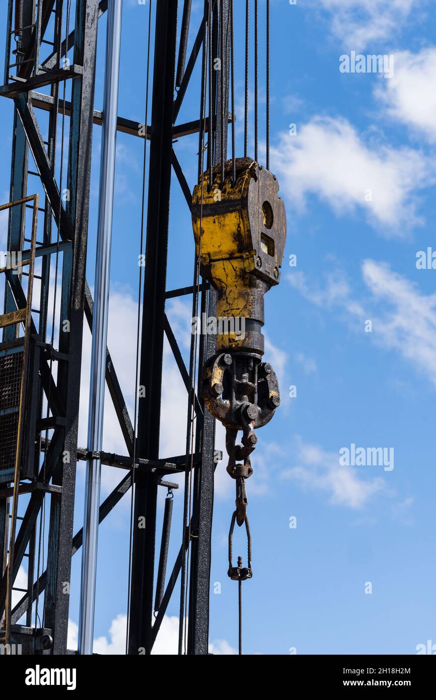
Cameron provides traveling blocks from 275- to 1,250-tonUS. Precise weighting of our traveling blocks ensures fast free-fall, while their streamlined, compact design eliminates interference with mast or derrick components. Their long service life is enhanced through quality fabrication and the advanced metallurgy of sheaves, beckets, and components. Cameron traveling blocks feature low-inertia sheaves for high performance and reliability.

This website is using a security service to protect itself from online attacks. The action you just performed triggered the security solution. There are several actions that could trigger this block including submitting a certain word or phrase, a SQL command or malformed data.
After an oil drilling rig drills a well and installs the well casing, the rig is dismantled and removed from the site. From that point on, a mobile repair unit, or workover rig, is typically used to service the well. Servicing includes, for example, installing and removing inner tubing strings, sucker rods, and pumps. This is generally done with a cable hoist system that includes a traveling block that raises and lowers the aforementioned tubing strings, sucker rods, and pumps. [0001]
U.S. Pat. No. 4,334,217 describes a system for monitoring the movement of a travelling block on a drilling rig. As described in the "217 patent, the traveling block can be raised or lowered beyond a safe limit. This is called “crown out” if the traveling block reaches its upper most safe position, and “floor out” if it reaches its lower most safe position. Crown out/floor out can result in equipment damage and/or present a hazard to personnel working on the equipment. Because it is often not possible for the operator of the cable hoist system to see the position of the traveling block, or because the operator can be otherwise distracted from the position of the traveling block, the operator can inadvertently exceed safe positions of the traveling block. [0002]
Although the "217 patent set out to solve the problem of unsafe hoist operation in an oil drilling rig, many drawbacks still remain when applying the "217 patent technology to a workover rig. For instance, hoist systems of workover rigs are much faster than those in oil drilling rigs, and the "217 system is not responsive enough to prevent the faster moving traveling block from crowning out or flooring out. Furthermore, the automatic switch-off system of the "217 patent provides for an abrupt stopping of the hoist system and traveling block. Abrupt stopping can cause an unsafe condition during workover operations and can possibly cause equipment damage, as the traveling block often supports a large amount of weight, often in excess of 100,000 pounds. [0004] SUMMARY OF THE INVENTION
The present invention improves on the "217 patent technology by providing a system that is both safer and more useful on workover rigs. The technology disclosed herein provides a system that calculates traveling block position, speed, weight, and momentum before applying a braking system to slow down and eventually stop the traveling block. The system takes these parameters into consideration when slowing and/or stopping the traveling block when it reaches a crown out or floor out position. The result is much safer operation of the traveling block on a workover rig, as well as on an oil drilling rig.[0005]
Referring to FIG. 1, a retractable, self-contained workover rig [0018] 20 is shown to include a truck frame 22 supported on wheels 24, an engine 26, a hydraulic pump 28, an air compressor 30, a first transmission 32, a second transmission 34, a variable speed hoist 36, a block 38, an extendible derrick 40, a first hydraulic cylinder 42, a second hydraulic cylinder 44, a monitor 48, and retractable feet 50. Engine 26 selectively couples to wheels 24 and hoist 36 by way of transmissions 34 and 32, respectively. Engine 26 also drives hydraulic pump 28 via line 29 and air compressor 30 via line 31. Compressor 30 powers a pneumatic slip (not shown), and pump 28 powers a set of hydraulic tongs (not shown). Pump 28 also powers cylinders 42 and 44 that respectively extend and pivot derrick 40 to selectively place derrick 40 in a working position (FIG. 1) and in a retracted position (FIG. 2). In the working position, derrick 40 is pointed upward; but its longitudinal centerline 54 is angularly offset from vertical as indicated by angle 56. This angular offset 56 provides block 38 access to a well bore 58 without interferences from the derrick framework and allows for rapid installation and removal of inner pipe segments, such as inner pipe strings 62 and/or sucker rods (FIG. 3).
Once the weight, speed and position of the traveling block is known, the traveling blocks can be safely slowed and smoothly stopped by a braking system that takes into account these variables before applying the brakes to the traveling blocks. When seeking to prevent crown out, the system first senses the velocity and vertical position of the traveling blocks. Depending on which region (position) the blocks are in (FIG. 4), the processor compares the actual velocity to the maximum allowed velocity for that region. If the velocity is below the maximum allowed value, for example 2 feet per second in region [0024] 108 or maybe 4 feet per second in center region 112, then nothing happens. If on the other hand, the block velocity exceeds the desired maximum velocity for that particular region, the system can either alarm the operator he is going to fast, take away the operator"s throttle authority thus slowing the blocks down, throttle the engine down to a point where the speed is reduced to an acceptable level, or any combination of or all of the above. This methodology allows the crew to operate at full horsepower pulling heavy loads at full RPM at any point along the axis of 104-106 so long as a safe operating speed limit is maintained. Each zone of travel, 108, 112, and 110, will have a maximum traveling block speed, with the middle zone 112 having a maximum speed that is greater than that of the slowing down zones 108 and 110.
On the other hand, if the ascending velocity is greater than the predetermined value, than the system automatically signals the throttle controller to slow the speed of upwards travel, regardless of the set-point provided to the throttle controller by the workover rig operator. Slowing the engine blocks down as the blocks enter into region [0025] 108 inhibits over travel as the blocks are moving slow enough to be stopped before reaching the predetermined upper limit, thereby avoiding crown out. The system can provide for an obligatory slowing down zone (region 108) in which the maximum block velocity in this region is slower than that of region 112 and is limited to a velocity which allows and accounts for intrinsic delays created by the processing time, brake action time, and on the stopping distance between the entry of the block into region 108 and the crown. In other words, there is a time factor inherent in the system for the system to sense the speed of the traveling blocks, process the data, start the braking action, and then for the drum to actually apply the brakes. In some embodiments, this time is about one half of a second, but it is within the skill of those in the art to determine what this lag time is for each individual system. The end result is that the system is allowed adequate time to slow and stop the blocks before they reach the crown out or floor out positions. Regardless of the block velocity, when the block reaches a predetermined upper limit as shown in FIG. 4 as upper point 104 (Upper Travel Limit), the system will automatically stop the traveling block"s upward movement, by reducing the engine to an idle, releasing the drum clutch, and setting the drum parking brake.
A further embodiment of the present invention as it pertains to preventing crown out is a “failsafe” omni reading metal detector located near the crown of the rig. In one embodiment, this detector is a Banner S [0026] 18M. When this metal detector is properly wired to the rig, which is within the skill of one familiar with such detectors, it provides an auxiliary means of stopping traveling block travel when it nears a crown out position. When placed in series with the clutch, engine throttle, and brake actuators, for example, if the detector senses metal (the traveling block), it opens the clutch, throttle, and brake circuits, thereby stopping the upward movement of said blocks. Therefore, if the processor or encoder fails during normal operation, the detector becomes a final safety device for stopping the traveling block. The detector should be set and calibrated so it will not to trip when the blocks are traveling in the normal derrick operating region, but will trip, and therefore open the circuits, when the blocks get too close to the crown, regardless of whether the encoder or processor are active or are operating normally. Thus, in the event of a processor failure, a total electrical failure, an encoder failure or other type of system failure, the metal detector will still prevent the traveling blocks from running into the crown:
When the block is traveling downwardly through region [0027] 108 and 112, if the velocity is below a predetermined or calculated maximum regional value, for example 8 feet per second, nothing happens. When the blocks travel into lower region 110 which is near the lower stopping point 106, the maximum allowable velocity is reduced, but again, as long as the measured velocity in that region is below the set limits, nothing happens. The maximum downward velocity in regions 104 and 108 can be input into the control system as a predetermined value, or alternatively can be calculated by a simple algebraic equation. This type of equation can take on many forms, but in one simple form this equation takes into account the weight and momentum of the traveling block. Since weight can be measured at (92), we can compute the maximum allowed velocity based on the hookload dividing the maximum allowed momentum figure by the weight, as shown below: Velocity max=Momentum(max)/Traveling Block Weight
Referring now to FIG. 4, a workover rig is shown with the block supporting a string of tubing. The blocks total travel is between the crown of the hoist [0032] 55 and the floor at the well head 58. A point before crown out is the upper limit of travel 104 where the traveling block will be completely stopped by the system. A point before floor out is the lower limit of travel 106 where the traveling block will also be completely stopped by the system. A range below the upper limit is the upper protected travel range 108. As described above, in this range if the velocity exceeds a predetermined value, a signal is sent to the engine governor to slow down the velocity of the traveling block so that when it reaches its upper limit of travel 104 it can be safely stopped. Similarly, a range above the lower limit is the lower protected travel range 110. As described above, in this range the velocity and weight (if desired) is measured, and if the velocity or momentum of the traveling block exceeds a predetermined value, a signal is sent to the brake to begin slowing down the traveling block so that when it reaches its lower limit 106 it can be safely stopped.
Referring now to FIGS. [0034] 5-9, a further embodiment of the present invention is shown in graphical form. When the block is traveling down, as shown in FIG. 5, the momentum of the block could be calculated by multiplying the weight on the block by the speed, or velocity, of the block. The distance needed to bring the load to a full stop will increase as the momentum increases. Therefore, a stopping distance “SD” is calculated by multiplying the momentum of the block times a “K” value, which is simply an input in the control system that is breaking the block. The rig mounted control system calculates the stopping distance based on this equation. The stopping distance is defined herein as the distance above the lower stop limit of the block. The lower stop limit is the lowest point at which the block is allowed to travel, and will usually be set in the control system by the rig operator.
Referring first to FIG. 5, the block is shown to be moving down at a speed of 20 feet per second. If the hookload is, for example, 100,000 pounds and a K value of 0.00001 s/lb is used by the computer, the stopping distance SD would be calculated to be 20 feet above the lower stop limit. When the block reaches the calculated stopping distance point, the control system would then send a variable electric signal via a PID loop to the breaking device on the rig. In one embodiment, the electric signal would be sent an electro-pneumatic transducer or proportional valve whose function is to take the electrical signal and output an air pressure proportional to the electrical signal. The output air from is then piped to an actuating air cylinder on the brake, thereby starting the braking action on the block. In one embodiment, a PID controller (proportional integral derivative) is used to slow the block between the stopping distance point to the lower stop limit. A PID controller would simply monitor the velocity or the momentum of the block and send a signal to the aforementioned electro-pneumatic transducer or proportional valve to add or reduce air pressure as needed to stay on the desired deceleration curve, as shown in FIG. 5. [0035]
A further embodiment of the present invention involves a momentum governor for the rig. This momentum governor is not only useful to protect crown out and floor out of the traveling block, but also is useful for protecting the rig and crew members from over-stressing the tubulars and the derrick while the rig is running tubulars into the hole. In standard operation, when running into the whole, it is desirable that the traveling block be allowed to fall freely through regions [0038] 108 and 112 if lightly loaded, slowing it down or regulating its speed if it is heavily loaded. FIG. 12 illustrates one example of this concept. For instance, if the weight on the traveling blocks is less than 20,000 pounds, they are allowed to travel at speeds up to 20 feet per second. As the hook load gets heavier, the maximum allowed velocity is lowered so as to maintain the momentum of the traveling block within a save envelope. For instance, according to this chart, at 40,000 pounds on the block the maximum downward velocity may be 11 feet per second. Finally, at hook loads above 75,000 pounds, the maximum downward velocity would be around 4 feet per second. This momentum governor would only apply to regions 108 and 112 of FIG. 4, and would have no application in the aforementioned floor out control portion of the crown out/floor out apparatus. Of course, the weights and speeds listed herein are used for example purposes only. The actual values used will differ from rig to rig and will need to be determined by the rig operator before using this momentum governor. The actual values will depend on a number of factors, including type of rig, operating parameters of the rig operator, and the safety level the operator wishes to operate under.
In one example of this system in application, assume that the operator is running a heavy string of tubing into the hole and exceeds the maximum allowed velocity. If the bottom of the tubing were to stack out on a scale ledge, if only for a moment, if the blocks are descending too rapidly, it will overrun the tubing after the tubing has stopped its downward movement. If the tubing breaks loose, it can fall and cause a sudden impact on the traveling block. This is actually a common occurrence in the field. The force of the free falling tubing, sometimes in excess of 100,000 pounds, can cause significant damage to the rig and tubing, causing an unsafe situation for the operator. Using this system, if the maximum velocity is exceeded, the traveling block is automatically slowed, thereby significantly reducing the chances of this type of catastrophic event by allowing the operator to catch the blocks before they are allowed to overrun the tubing. [0041]
In another embodiment of this invention, all near crown or near floor incidents are captured in a data logger. For example, whenever the rig control system takes control of the blocks and stops them because they are too near the stop points, it is captured as an event and stored on a computer resident with the service rig. This event can then be transmitted to a central computer system, making it available to the management of the well service company. Since it is recorded, the well service company will be able to tell if the operator ran the rig dangerously or running it too close to the limits of the rig. [0042]
While the apparatuses and methods of the present invention have been described in terms of preferred embodiments, it will be apparent to those of skill in the art that variations may be applied to what has been described herein without departing from the concept and scope of the invention. All such similar substitutes and modifications apparent to those skilled in the art are deemed to be within the scope and concept of the invention as it is set out in the following claims. For instance, many of the embodiments were described as being useful on well service rigs, however each embodiment is equally useful on standard drilling rigs and other types of oil rigs. [0043]
One common piece of heavy equipment used to produce hydrocarbons from the earth is referred to as: a workover rig, a completion rig, or a pulling unit. Such a thing can do many tasks, but it is primarily used to hoist damaged tubing from a well and lower undamaged tubing into a well so that oil and gas can flow more freely. A workover rig can also be used to “complete,” repair, or swab a well to maximize its rate of fluid production.
A workover rig comprises a truck carrying a telescoping mast and a winch. In use, the truck is backed up to a well, the mast is raised, and the lifting of tubing is initiated using the winch. A typical, workover rig is used only during daylight hours. A workover rig cannot drill into the earth unless equipped with a special “power swivel” that moves up and down while turning drill pipe extending into the well.
Thousands of men in the United States work upon workover rigs and are interested in workover rigs. It is believed that many would like to own a functioning model of such a rig. Duplicating every feature of a workover rig in a mass-produced model, however, is not practical since many features would be tiny and especially costly to make. Changes are necessary in the various apparatus that: pivots the mast to its substantially perpendicular, upright orientation, telescopes the mast to its full length, and hoists tubing.
In light of the problems associated with replicating a full-size workover rig at a small scale, it is a principal object of the invention to provide a toy workover rig with means for pivoting, telescoping, and hoisting that are lifelike in operation if not exact in appearance.
It is another object of the invention to provide a toy workover rig of the type described that is radio controlled. A person with minimal experience can operate the toy workover rig without resort to prolonged training, study aids, or additional tools. An oil and gas operator can even employ my toy workover rig during a new hire"s orientation session to provide a familiarity with a rig"s working parts and function.
It is an object of the invention to provide improved elements and arrangements thereof in a toy workover rig for the purposes described which is lightweight in construction, inexpensive to make, and fully dependable in use.
The toy workover rig in accordance with this invention achieves the intended objects by featuring an extensible mast that is pivotally fastened to a wheeled truck. A remotely-controlled pivoting assembly is connected to the truck for selectively moving the mast from a horizontal, traveling position to a vertical, operating position. A remotely-controlled telescoping assembly is connected to the truck for selectively extending the mast from a retracted position to an extended position. A remotely-controlled hoisting assembly is connected to the truck for lifted selected objects within the mast.
The foregoing and other objects, features and advantages of my toy workover rig will become readily apparent upon further review of the following detailed description of the preferred embodiment illustrated in the accompanying drawings.
Referring now to the FIGS., a toy workover rig in accordance with the present invention is shown at 10. Workover rig 10 includes a truck 12 that carries an extensible mast 14 at its rear. Mast 14 can be selectively moved from a horizontal, traveling position to a substantially perpendicular, vertical, operating position by a pivoting assembly 16. A telescoping assembly 18 is employed to selectively extend mast 14 to its full height. A hoisting assembly 20 selectively lifts a joint of tubing 22 within mast 14. Assemblies 16, 18 and 20 of the rig 10 are operated by remote control.
Truck 12 includes an elongated body 24 that is supported above the ground by a number of rotatable wheels 26. A cab 28 is affixed to the front of body 24. A pair of upright braces 30 is affixed to the rear of body 24 for pivotally securing mast 14 thereto. Each of braces 30 has a diagonal member 32 and a vertical member 34 being connected together so as to form an inverted V-shape. The tops of braces 30 are positioned at a height that is somewhat greater than that of cab 28 and carry hinges 36 to which mast 14 is pivotally connected. A mast support 38 is affixed to body 24 behind cab 28 for holding mast 14 above cab 28 when mast 14 is pivoted downward for safe movement of workover rig 10 from place to place. A dummy motor 40 is affixed to body 24 adjacent support 38.
Body 24 is provided with a number of ground-engaging stabilizers 42 and 44 to prevent it from tipping when mast 14 is pivoted substantially perpendicular upright and telescoped. A pair of center stabilizers 42 is provided at the midpoint of body 24 with one being located on each side of body 24. Each of stabilizers 42 has a guide sleeve 46 in the bottom of body 24 and an arm 48 that fits snugly, yet slidably, within sleeve 46. Each sleeve 46 is configured such that, when a moderate pushing or pulling force is applied to the associated arm 48, arm 48 is moved within sleeve 46 along an axis that extends downwardly and outwardly from body 24. When fully extended, each arm 48 contacts the ground at a point that is not beneath body 24 thereby preventing body 24 from tipping sideways. Additionally, a pair of rear stabilizers 44 is provided at the rear of body 24 with one being located on each side of body 24. Each stabilizer 44 has a vertically oriented, guide sleeve 50 in the bottom of body 24 that is internally, helically threaded. A helically threaded rod 52 is screwed into each sleeve 50. When screwed outwardly, each rod 52 is brought into contact with the ground beneath body 24 preventing body 24 from tipping rearwardly.
Housing 54 carries several joints of tubing 22 for lifting by rig 10. Two columns of hooks (not shown) are affixed to one of side walls 60 so that the hooks of each column have horizontally positioned counterparts in the other column. The columns are set at a distance apart that is somewhat less than the length of a joint of tubing 22. Removably positioned on each pair of horizontally spaced hooks is a joint of tubing 22.
A ladder 76 is affixed to, and extends along, truss 68 l. Beneath ladder 76, an operator"s platform 78 is pivotally fastened to truss 68 l. Platform 78 has a pair of pegs 80 that carry a detachable handrail 82. Handrail 82 has a pair of pins 84 at its bottom that can be inserted into a pair of tight-fitting sockets (not shown) in the outer edge of platform 78. When mast 14 is pivoted substantially perpendicular upright, platform 78 is manually pivoted to a horizontal orientation and pins 84 are inserted into the sockets to hold the handrail 82 in a vertical orientation.
A work floor 86 is pivotally connected to bottom section 14 b. Work floor 86 comprises a U-shaped plate 88 having a pair of ground engaging legs 90 hingedly fastened thereto. One of a pair of hinges 92 pivotally connect the front of plate 88 to the bottom of lateral truss 681 and the other of hinges 92 pivotally connects the front of plate 88 to the bottom of lateral truss 68 r. A cutout (not shown) in the front of plate 88 between hinges 92 provides additional ground access for traveling block 94 and items carried thereby. When mast 14 is pivoted substantially perpendicular upright, plate 88 is manually pivoted to a horizontal orientation to the rear of mast 14 and legs 90 are pivoted downwardly to a vertical orientation to engage the ground and retain plate 88 in a horizontal orientation.
Tubing board 128 is pivotally connected to top section 14 tand extends rearwardly from it. Tubing board 128 has a U-shaped retainer 132 that is pivotally connected at its front to tubing board braces 102. Affixed to the rear of retainer 132 are a number of forwardly facing tines 134 that define spaces therebetween for racking pieces of tubing 22 lifted by traveling block 94. One of a pair of handrails 136 is rigidly affixed to each of the opposite sides of retainer 132. For compact storage when mast 14 is pivoted downwardly onto mast support 38, another handrail 138 is pivotally secured at its bottom to the rear of retainer 132.
Rod basket 130 is pivotally connected to top section 14 tand extends rearwardly from it. Rod basket 130 has a U-shaped retainer 140 from which a basket member 142 is suspended by its U-shaped top rail 144. For compact storage, retainer 140 is pivotally connected at its front to rod basket braces 106 and the rear of top rail 144 is pivotally connected to the rear of retainer 140. (The front of retainer 140 is open and configured in a manner that prevents retainer 140 from pivoting to a position more than a few degrees beyond horizontal when mast 14 is pivoted to an upright, substantially perpendicular position.) Extending sideways from the front of top rail 144 is a pair of retaining pins 146 that abut the top of retainer 140 and maintain basket member 142 in an upright, substantially perpendicular position when the mast 14 is pivoted substantially perpendicular upright.
Pivoting assembly 16 operates to swing mast 14 substantially perpendicular upright on hinges 36. Pivoting assembly 16 includes an electric motor 148 mounted atop truck body 24 between braces 30. Motor 148 drives a gearbox 150 that effectively increases torque. Gearbox 150 has a horizontal driveshaft 152 that is rotated by motor 148.
Telescoping assembly 18 operates to lift top section 14 tabove bottom section 14 bwhen mast 14 is swung to an upright orientation by pivoting assembly 16. Telescoping assembly 18 includes an electric motor 168 affixed to the bottom of bottom section 14 bbetween lateral trusses 68 rand 68 l. Motor 168 drives a gearbox 170, also affixed to the bottom of bottom section 14 b, having two meshing gears for transmitting power from the motor 168 to a driveshaft 172 extending upwardly from the gearbox 170.
A user of workover rig 10 can easily distinguish when top section 14 thas reached the upper limit of its travel. The first and easiest way to make such a determination is to see that the top portions of trusses 66, 68 rand 68 land the bottom portions of trusses 96, 100 rand 1001 line up horizontally. Another way involves an examination of tubing board 128 and rod basket 130. Their principle features should extend horizontally and vertically so that it is substantially perpendicular.
Pulleys 188 on opposite sides of workover rig 10 receive cords 184. As shown, cords 184 run under pulleys 124 and over pulleys 188. Pulleys 124 and 188 prevent cords 184 from binding and tangling while top section 14 tis being extended or retracted from bottom section 14 b.
A hook 226 is suspended from rod 216 between bells 218. Hook 226 can be employed to catch and suspend miscellaneous tools used with rig 10. Optionally, hook 226 may incorporate a swivel mechanism 228 to permit it to rotate in any direction relative to rod 216.
The operation of workover rig 10 is by three-channel, remote control. A transmitter 250 broadcasts electrical operations signals to a receiver 252 carried within truck body 24 to activate one of a number of servos 254, 256 and 258 also carried within truck body 24. Activating servos 254, 256 and 258 closes dual-throw switches 260, 262, or 264 to selectively operate motors 148, 168 and 248 to move mast 14 or traveling block 94.
When mast 14 is fully pivoted to an upright position, substantially perpendicular work floor 86 is manually pivoted away from bottom section 14 b. Then, with work floor 86 in a horizontal orientation, legs 78 are pivoted downwardly and engaged with the ground. Afterward, when play with rig 10 is complete, work floor 86 is returned to its original position against bottom section 14 band mast 14 is pivoted down upon support 38.
When play with rig 10 is complete, mast 14 can be returned to a compact state like that found on a real workover rig that is being driven over the road. Rig 10 is most easily stored in this condition. Others may prefer to keep mast 14 in an upright, substantially perpendicular and fully extended condition. In this manner, rig 10 makes a great display model and focal point wherever set up.
While workover rig 10 has been described above with a high degree of particularity, it will be appreciated by those skilled in making toys that modifications can be made to it. For example, wheels 26 beneath cab 28 can be made to turn via remote control to steer truck 12 and a remotely controlled motor (not shown) can be added to drive a set of wheels 26 and propel truck 12 over the ground. (Such things are, of course, commonly found in r/c cars.) Also, downwardly pivoting toolbox doors 274, sidewalks 276 and movable ladders 278 can provide added realism. So, it is to be understood that my invention is not limited solely to workover rig 10, but encompasses any and all workover rigs within the scope of the following claims.

The rig assist unit was installed on top of the rig’s Bops. A landing joint was lowered into the stack and screwed into the tubing hanger. The snubbing Bops were tested using the rig pump to 35mpa

This website is using a security service to protect itself from online attacks. The action you just performed triggered the security solution. There are several actions that could trigger this block including submitting a certain word or phrase, a SQL command or malformed data.

n: a record made each day of the operations on a working drilling rig and, traditionally, phoned, faxed, emailed, or radioed in to the office of the drilling company and possibly the operator every morning.
(pronounced "tower") n: in areas where three eight-hour tours are worked, the shift of duty on a drilling rig that starts at or about daylight. Compare evening tour, morning (graveyard) tour.
(pronounced "tower") n: in areas where two 12-hour tours are worked, a period of 12 hours, usually during daylight, worked by a drilling or workover crew when equipment is being run around the clock.
n: the crew member who handles the upper end of the drill string as it is being hoisted out of or lowered into the hole. On a drilling rig, he or she may be responsible for the circulating machinery and the conditioning of the drilling or workover fluid.
n: a high-compression, internal-combustion engine used extensively for powering drilling rigs. In a diesel engine, air is drawn into the cylinders and compressed to very high pressures; ignition occurs as fuel is injected into the compressed and heated air. Combustion takes place within the cylinder above the piston, and expansion of the combustion products imparts power to the piston.
n: the employee normally in charge of a specific (tour) drilling or workover crew. The driller’s main duty is operation of the drilling and hoisting equipment, but this person may also be responsible for downhole condition of the well, operation of downhole tools, and pipe measurements.
n: an internal-combustion engine used to power a drilling rig. These engines are used on a rotary rig and are usually fueled by diesel fuel, although liquefied petroleum gas, natural gas, and, very rarely, gasoline can also be used.
n: a type of portable service or workover rig that is self-propelled, using power from the hoisting engines. The driver"s cab and steering wheel are mounted on the same end as the mast support; thus the unit can be driven straight ahead to reach the wellhead.

A blowout preventer that uses rams to seal off pressure on a hole that is with or without pipe. It is also called a ram preventer. Ram-type preventers have interchangeable ram blocks to accommodate different O.D. drill pipe, casing, or tubing.†
A pit in the ground to provide additional height between the rig floor and the well head to accommodate the installation of blowout preventers, ratholes, mouseholes, and so forth. It also collects drainage water and other fluids for disposal.†
A small enclosure on the rig floor used as an office for the driller or as a storehouse for small objects. Also, any small building used as an office or for storage.†
The hoisting mechanism on a drilling rig. It is essentially a large winch that spools off or takes in the drilling line and thus raises or lowers the drill stem and bit.†
On diesel electric rigs, powerful diesel engines drive large electric generators. The generators produce electricity that flows through cables to electric switches and control equipment enclosed in a control cabinet or panel. Electricity is fed to electric motors via the panel.†
Shallow bores under the rig floor, usually lined with pipe, in which joints of drill pipe are temporarily suspended for later connection to the drill string.†
A diesel, Liquefied Petroleum Gas (LPG), natural gas, or gasoline engine, along with a mechanical transmission and generator for producing power for the drilling rig. Newer rigs use electric generators to power electric motors on the other parts of the rig.†
A hole in the rig floor 30 to 35 feet deep, lined with casing that projects above the floor. The kelly is placed in the rathole when hoisting operations are in progress.†
Shallow bores under the rig floor, usually lined with pipe, in which joints of drill pipe are temporarily suspended for later connection to the drill string.†
The hose on a rotary drilling rig that conducts the drilling fluid from the mud pump and standpipe to the swivel and kelly; also called the mud hose or the kelly hose.†
The top drive rotates the drill string end bit without the use of a kelly and rotary table. The top drive is operated from a control console on the rig floor.†
The claimed invention relates generally to well drilling and servicing equipment, and more specifically to portable rigs for handling pipe strings when making up and disconnecting long strings of pipe used in a bore hole during operations that are carried out in the exploration and production of petroleum and other fluids and minerals from substantial depths below the earth"s surface.
When such service operations become necessary, a portable installation called a workover rig is brought to the well site and set up. Generally, these rigs consist of a derrick or mast which supports pulleys or block and tackle arrangements that are operable to pull the pipe string from the well. These prior art workover rigs are usually heavy and difficult to erect and further often have the limited operational capability of only being able to hoist or pull pipe from a well without the capability of snubbing or pushing pipe back into the well. Since these conventional workover rigs cannot develop a downward force to push a string of pipe into the well, in such operations the well must necessarily always be under control or "dead", as is known in the art. This may require a preparatory operation of injecting a suitable substance such as mud or "kill" fluid into the well to maintain sufficient column weight of fluid to resist the pressure within the well which is tending to force the tubing out. However, it is usually desirable to carry out the workover operations without resorting to the injection of "kill" fluid into the well since the well may be lost if the formation is damaged because of the presence of the workover "kill" fluid. In such "killing" workover operations, there is a very high risk that the productivity of the subsurface formation may decline so severely after killing the well that the well must be abandoned.
An overriding concern in the construction of workover rigs is to get the necessary equipment into and out of the well as rapidly and safely as is economically possible. This concern has led to the development of a portable well service rig having a transportable mast or derrick. Before the invention of the first portable well service unit, it was necessary to leave the drilling derrick in place over the well for use in future well service operations. The portable well service rig eliminated the need for a permanent derrick and thus materially reduced overall well service costs. The early portable rigs, however, were unloaded in a heap and later sorted out, and then assembled without any definite plans therefore consuming a substantial amount of time in rigging up. Even when unitized and transported on pallets, a significant amount of time was required for transporting, rigging up and dismantling the palletized equipment. In the palletized approach, the field assembly and erection of the mast, mast support structure and reeving of the hoist cable caused expensive but unavoidable delays. Therefore recent improvements to conventional portable workover rigs have focused on changes which simplify the operations of transporting, rigging up and dismantling.
One of the problems associated with the development of the portable workover rig is that of providing sufficient working space below the mast floor while limiting the mast and its supporting base to dimensions which permit its transportation across public highways. A working space must be provided below the mast floor in order that the mast can be supported vertically above and engage well head equipment which may extend as much as eight to ten feet above the elevation of the rig platform deck. The minimum height of the mast is determined primarily by the length of the sections of pipe string added to or removed from the pipe already in the well bore. However, if the mast is so high that its length and height clearance when in a horizontal position on the workover rig exceeds the limits allowed by the state, the mast must be at least partially disassembled or must be telescoped. Most wells have tubing sections which are in the range of thirty-six to forty feet long, so that the construction of a transportable mast assembly having a stroke for accomodating the removal or insertion of such tubing sections poses no problem insofar as complying with state highway regulations.
As mentioned above, the conventional practice has been to provide a mast having telescoping sections or having sections which must be separately assembled and erected on site. To provide ample clearance for the well head equipment, the mast floor has been elevated above the ground level by placing it on a mast substructure carried by the rig base platform. This substructure is normally fabricated of heavy structural steel in a massive weldment which must be separately transported. The loads it must bear are greater than those born by the mast, since the substructure must support not only the weight of the derrick with its pipe string load, but other loads, such as the rotary table and draw works as well. However, the length and height of the separate mast support base when combined with the reclining mast may in some cases exceed highway limits, so that separate transportation, field assembly and erection are required. Most conventional rigs provide separate support base and mast sections which may be unbolted and separately transported to provide the short lengths allowed for highway travel. However, additional rigging up and tear down time is required for such arrangements.
Other important considerations involved in the construction of portable workover rigs are the strength and stability of the mast. The mast must be constructed to safely carry all loads which will ever be used in the well over which it is placed. This is the collapse resistance caused by vertical loading, or the dead load capacity of the mast. The largest dead load which will be imposed on the derrick will normally be the heaviest string of production tubing run in the well. However, this heaviest string of tubing will not be the greatest strain placed on the mast. The maximum vertical load which will ever be imposed on the mast will probably be the result of pulling on equipment, such as drill pipe or casing, that has become stuck in the hole. Therefore it must be considered that, sometime during the useful life of the mast, severe vertical strain will be placed on it because the equipment has become stuck in the hole. Therefore the mast and its intermediate support platform must be constructed to withstand and react loads which will exceed the capacity of the hoist line which will be used on the rig.
The mast must be also designed to withstand the maximum wind loads to which it will be subjected. The horizontal force of the wind acting on the mast and production tubing is usually counteracted by using from one to three guy wires along each leg of the mast which are attached to "dead man" anchors located some distance from the mast. A "dead man" anchor is made from a short length of large pipe, a concrete block, or a short section of timber, which is buried in the ground to provide an anchor for the guy wire. A substantial amount of time and labor is expended in setting up the "dead man" support lines. Additionally, when carrying out workover operations off shore, there is no practical way to anchor the guy lines. A suitable structural alternative for the guy wire supports is necessary for reacting the wind loads, and the snubbing forces must also be reacted in order to drive production tubing into an offshore well against the downhole pressures which may be encountered. Therefore there is a continuing interest in improving the design of support substructure for free-standing masts which do not require guy wires for support.
As a result of the many improvements to portable workover rigs, such vehicles now transport practically all the necessary servicing equipment directly to the field locations and when servicing has been completed, remove the necessary equipment to another well in need of service in the same field or in a different field miles away. Thus the equipment necessary to service a number of wells each having different service requirements has been greatly reduced, and consequently the labor and cost, as well as the amount of equipment has correspondingly dropped. However, there still remains considerable interest in the provision of more efficient and simplified machines in order that the job of well servicing in general may be carried out efficiently and at reasonable cost.
It is, therefore, the principal object of the present invention to provide an improved general purpose workover rig having a unitized configuration which is transportable across public highways and which can be easily rigged up and dismantled in the field.
Still another object of the invention is the provision of a workover rig having a mast, a mast support substructure, and draw works in which the static load of the draw works is supported by a portable base platform member rather than by being supported by the intermediate mast support substructure.
Yet another object of the invention is the provision of a workover rig having draw works carried by a portable platform and a mast and mast support substructure which are separately movable from a reclining transport position to an erect operating position wherein erection and retraction of the mast and mast support assembly can be carried out without disturbing cable reeving on the mast or on the draw works.
An important object of the present invention is the provision of draw works for a workover rig which can be carried in a reclining position on a portable rig platform and which is operably connected to develop driving forces required for either hoisting or snubbing operations.
Still another object of the invention is the provision of a portable workover rig having a mast and mast support substructure which are separately movable from a reclining transport position over a portable base platform to an erect workover position overlying well head equipment lying either above or below the elevation of the portable base platform.
Yet another object of the invention is the provision of a base support substructure for an erectable mast and a carriage assembly for moving the base support substructure from a reclining transport position over a portable base platform to an erect workover position, the carriage assembly cooperatively coupled to the base platform for stabilizing the erectable mast in free-standing relation on the mast support substructure and for transmitting mast load reaction forces through the portable base platform.
Another object of the invention is the provision of a workover rig having an erectable mast supported on a cantilever support substructure which is movable from a reclining transport position overlying a portable base platform to an elevated position of use wherein the cantilever support base is extended beyond the portable base platform for carrying out workover operations.
The foregoing objects are achieved by a workover rig which is mounted on a portable base platform such as a skid or the bed of a trailer vehicle, and which features a collapsible mast assembly which is movable from a reclining transport position to an erect elevated position of use. The mast assembly is supported for freestanding operation by a carriage assembly including a cantilever substructure support base mounted on the rig support platform for pivotable movement from the reclining transport position to an elevated position of use. The carriage assembly includes lift arms coupled in parallel relation intermediate the cantilever support structure and the rig support platform, thereby defining a parallelogram throughout the range of movement of the mast support assembly for maintaining the cantilever support base in parallel alignment with the base platform. According to this arrangement, the mast and the carriage assembly are separately collapsible for transport in a low profile, reclining position over the base platform to comply with the length and height limitations established for public highways. The mast and the carriage assembly are separately erectable to an elevated operating position overlying well head equipment which may be disposed at an elevation either above or below the elevation of the portable base platform. The mast is connected in hinged engagement with the carriage assembly, and both the carriage assembly and the mast are separately driven from the transport position to the erect operating position by linear hydraulic actuators. The linear hydraulic actuators in combination with the carriage assembly serve to stabilize the mast for free-standing operation and transmit mast load reaction forces through the portable base platform. An important feature of this arrangement is the cantilever support substructure which is extended to an elevated operating position beyond the portable base platform for carrying out workover operations adjacent elevated well head equipment. A further advantage of this arrangement is that the mast, mast support substructure, and draw works can be carried in a collapsed, low profile transport position and both erection and retraction of the mast and mast support assembly can be carried out without disturbing the cable reeving on the mast and draw works.
According to an important aspect of the invention, the workover rig is provided with a mast, a mast support substructure, and draw works in which the static load of the draw works is supported by a portable base platform member rather than being supported by the intermediate mast support substructure. In this arrangement, the draw works includes a linear hydraulic actuator having rod and housing elements in which one of the elements is anchored to the base platform with the other element being mounted for movement along the base platform through a stroke pathway which extends transversely with respect to the mast. The traveling sheaves are cooperatively reeved with hoist and snub cables for developing driving forces required for either hoisting or snubbing operations. The advantage of this arrangement is that the intermediate mast support substructure must support only the mast in an erect operating position with the substantial weight of the draw works being supported by the portable base platform. This arrangement permits the mast support substructure to be easily movable from the reclining, low profile transport position to the elevated workover position without the burden of the draw works. Hoisting and snubbing operations are carried out by the draw works which includes a linear hydraulic actuator carried on the base platform, a load engaging traveling block supported for vertical movement along the mast by hoist and snub cables, and by traveling sheaves carried by the actuator through a stroke pathway which is oriented transversely with respect to the mast. In this arrangement the load engaging traveling block is driven upwardly or downwardly along the mast in response to extension and retraction of the rod and housing elements of the hydraulic actuator.
In yet another important embodiment of the invention, a vertically adjustable stack assembly is provided for accomodating the existing elevation of well head flange connections. The vertically adjustable stack assembly includes an adjustable support column assembly anchoring the rig platform to the well head casing, and an adjustable support column assembly interposed between the well head casing and the mast for transferring the weight of the mast from the intermediate mast support structure to the well casing. The vertically adjustable stack assembly simultaneously anchors the portable base platform to the well head casing, thereby stabilizing the mast support substructure, while relieving the burden of the mast from the intermediate mast support substructure. This arrangement helps stabilize the mast for free-standing operation on the mast support substructure and for transmitting mast load reaction forces through the portable base platform, thereby eliminating the need of dead man anchor lines which would otherwise be required for stabilizing the mast and for reacting dynamic mast loads.
Finally, the portable workover rig of the invention is adapted to perform drilling operations by the combination of a vertically yieldable stab assembly which interconnects a powered drill sub with a traveling block for permitting vertical displacement of the powered drill sub during make-up and break-out operations while simultaneously reacting torque forces which arise in response to rotary forces applied to the drill string. The vertically yieldable stab assembly includes upstanding stab receptacles anchored to the top side of the traveling block and stab elements downwardly depending from the under side of the powered drill assembly for engagement with the stab receptacles. Each stab element is supported for vertical reciprocal movement between retracted and extended positions, and each stab element is yieldably biased to the fully extended position, thereby permitting vertical displacement of the power sub relative to the traveling block during the make-up and break-out operations while reacting torque forces which are produced by operation of the powered drill sub.
FIG. 3 is a top plan view of the workover rig of FIG. 1 with the mast and carriage assembly removed which illustrates the layout of the draw works and related equipment on the deck of a portable rig support platform;
FIG. 7 is a side elevational view of a skid mounted workover rig having draw works and an erectable mast constructed according to the teachings of the present invention;
FIG. 10 is a perspective view which illustrates the arrangement of sheaves and reeving of cables for conducting snubbing operations on the workover rig shown in FIG. 1;
FIG. 11 is a perspective view which illustrates the arrangement of sheaves and reeving of cables for conducting hoist operations on the workover rig shown in FIG. 1;
FIG. 16 is a front elevation view of the completed vertically adjustable stack assembly shown interconnecting the mast support substructure and the rig support platform with the flanged connector of a well head assembly;
Referring now to the drawings, and more particularly to FIGS. 1-4, a workover rig 10 is shown having a transportable mast assembly 12 and draw works 14 supported on a portable trailer platform 16. The trailer platform 16 includes the usual longitudinal side frame rails 18, 20 which supports forward and rear decks 22, 24, respectively. The side rails 18, 20 are interconnected by the usual structural members, including a tailboard 26. The trailer platform 16 includes a fifth wheel connection 28 for attachment to a tractor, and rear wheels 30 supported by shock assemblies and leaf springs in the usual manner. Outrigger jacks or props 32 support the side frame rails 18, 20 to prevent tilting or overturning of the rig during operation and also for maintaining the orientation of the trailer platform 16 once it has been set up. The jacks 32 are preferably hydraulically actuated and are controlled from a central station so that the trailer platform 16 can be aligned in parallel with the ground or inclined in a tilted position for workover of slant wells. Each jack 32 is equipped with a stabilizer pad 34 for engaging a mud sill (not shown) so that the trailer load can be more evenly distributed. Slung underneath the side frame rails 18, 20 are tool boxes 36 and a spare tire 38. Anchored top side on the forward deck 22 is power unit 40 which develops the main hydraulic power for the draw works 14 and includes hydraulic pumps driven by a diesel engine. The power unit is coupled to a hydraulic reservoir 42 so that as the required pressure in the system exceeds predetermined levels, one or another pump automatically unloads into the reservoir 42 and all engine horse power is then diverted for driving the alternate pump(s). Immediately forward of the power unit 40 are a pair of fuel tanks 44, and overlying the fifth wheel connection 28 is a hose basket 46. Overlying the fuel tanks is an upstanding stop bar 47 for engaging the mast assembly and supporting it in spaced relation with the forward deck overlying the power unit and fuel tanks when the transportable mast assembly 12 is disposed in its reclining transport position, as illustrated in FIGS. 1 and 2. Also anchored to the trailer platform 16 intermediate the forward and rear decks is a guide tube 48 which is straddled by the hydraulic reservoir 42 for receiving the movable actuator element of the draw works 14 as will be discussed in greater detail below.
Referring again to FIGS. 1-4, the transportable mast assembly 12 comprises generally an elongated mast 50 pivotally mounted on a mast support substructure 52 which is in turn pivotally mounted on a mast carriage assembly 54 which is mounted for pivotal movement from a transport position shown in FIG. 2 to an elevated position of use shown in FIG. 1. The mast 50 is formed by two upstanding mast sections 50A, 50B which are laterally spaced to define a vertical load transport zone 56 through which a traveling block 58 is transported during pipe running operations. The upper ends of the mast sections 50A, 50B are structurally interconnected by a crown block 60 which improves the mechanical stability of the mast and which also serves to support crown block sheaves in a manner to be disclosed hereinafter. Each mast section 50A, 50B is defined by four leg members 62A, 62B, 62C and 62D, and 64A-D, respectively. The leg members are generally arranged at the corners of a square with the forward leg portions terminating in a clevis which receives a hinge pin 66 which pivotally secures the forward legs to the mast support substructure 52. Each mast section 50A, 50B is provided with girt members 68 and brace members 70 which are structurally interconnected with the leg members to insure rigidity of each mast section. A clevis 72 is anchored on opposite sides of the mast support substructure 52 for anchoring the rear legs 62B, 64B of the mast when it has been erected to the upright position.
Erection of the mast 50 to the upstanding, elevated workover position is preferably carried out by rotating the mast support substructure 52 from its reclining transport position to its fully extended upright position while the mast 50 remains in its reclining position. After the mast support substructure has been fully stabilized in the upright position, the hydraulic lift cylinders 80 are actuated to cause the mast 50 to be pivoted to its upright standing position on the cantilever support base 74. The hydraulic lift cylinders 78, 80 are continuously pressurized in order to further stabilize the mast support substructure and transmit mast loads to the trailer platform 16. Retraction of the mast 50 is carried out in the reverse order by first uncoupling the rear leg portions at the clevis 72 and retracting the double acting hydraulic lift cylinders 80 until the mast 50 is substantially horizontal. Thereafter, the hydraulic lift cylinders 78 are retracted until the mast support substructure is resting in its reclining transport position with the upper end of the mast resting on the tie-down bar 47.
The traveling block 58 is guided for vertical displacement along the rear legs 62A, 64D, which serve as guides, as can best be seen in FIGS. 4 and 23. The traveling block 58 includes a main cross member 98 which extends horizontally between the legs 62D, 64D and is provided with guide rollers 100 rotatably mounted about shafts 102 at either end of the frame. The periphery of each roller is concave to conform to the shape of the tubular members 62D, 64D and vertically guide the traveling block as it is reciprocated along the mast 50. A rotary table 104 is carried by the main cross member 98 of the traveling block to facilitate workover or drilling operations.
Referring to FIGS. 3, 4, 10, 11 and 19-21, the linear hydraulic actuator 92 is carried on the rear deck 24 of the trailer platform 16 and includes rod and cylinder housing elements 128 and 130, respectively. The rod element 128 is rigidly attached at one end to an anchor weldment 132 whereby the actuator assembly 92 is supported in spaced, parallel relation with the rear deck 24 so that the cylinder housing 130 can move freely in extension and retraction. Reciprocal movement of the cylinder 130 is stabilized by the guide tube 48 which receives the freely projecting end of the cylinder housing 130. The anchor weldment 132 includes a socket for engaging a threaded shaft portion 134 of the rod element 128.
The linear hydraulic actuator 92 is double acting and includes a piston 136 slidably received within the cylinder housing 130 which partitions the interior of the cylinder housing into head and rod chambers 138 and 140, respectively. The rod element 128 comprises two concentric tubes 142, 144 for circulating hydraulic fluid into the head chamber 138 and rod chamber 140, respectively. The inner rod tube 142 has a bore 146 which connects the head chamber 138 in fluid communication with a stepped concentric blind bore 148 which communicates with a lateral hydraulic flow passage 150. Similarly, a lateral flow passage 152 communicates with an annular passage 154 which extends intermediate the inner rod tube and the outer rod tube. Hydraulic fluid discharged through the annular flow passage 154 circulates through discharge ports 156 which communicate with the rod chamber 140. Appropriate O-ring seals 158, 160 seal the pressure chambers against fluid leakage. An end cap 162 blocks off the end of the cylinder housing 130. It will be seen, therefore, that the piston rod element 128 remains fixed to the anchor weldment 132 so that pressurization of either the head or rod chamber of the cylinder housing 130 will cause the cylinder housing to extend or retract.
Extension and retraction of the cylinder housing 130 is controlled from the operator platform 126 which is horizontally supported from the aft legs of the mast at an elevation convenient for workover operations. The forward part of the platform (not shown) houses hydraulic valves that control the actuation of the various components as will be explained.
Referring now to FIG. 16, the workover rig 10 is set up adjacent a well site in which a well casing 230 is terminated by a lower well head flange 232 and is anchored by a concrete block 234 in the usual manner. As is conventional, a blow out preventer 236 is located above and connected to the lower well head flange 232. A slip 238 is located above and connected to the blow out preventer 236. Located above and connected to the slip is an energizable packer 240. The packer is coupled to an upper well head flange 242 disposed at an elevation above the trailer platform as indicated by the elevation reference line 244. The BOP slip and packer are all concentrically aligned with the well casing 230 so that a tubing string may be moved upwardly through the well casing along the bore axis 248 as the tubing string is run out of the well. Conversely, when running the tubing string 246 into the well, each section is moved downwardly through the packer, slip and blow out preventer into the well casing 230.
The blow out preventer 236 may be of any suitable type, but is preferably hydraulically energizable for engaging the tubing string 246 in a fluid sealing relation to prevent the well from blowing out. The slip 238 may also be of any suitable construction and is preferably double acting, i.e., is preferably capable of preventing both upward and downward movement of the production tubing string. The packer 240 may not be present on some well head installations, in which case the upper well head flange 242 is located at a different elevation. The precise elevation of the well head flange termination 242 varies from well to well depending upon the length of the well head equipment which is used for terminating the well. This variation in the elevation of the well head flange pre


 8613371530291