
power steering pump as hydraulic pump free sample
To many, steering pump is just some magical black box that supposedly somehow makes our driving trips much more enjoyable. But how does a power steering pump works exactly?
If you clicked into this article, I bet you want to know more than just the surface. We can help with that. Today, we’re going to dive deep into the world of mechanics, particularly on the inner workings of a steering pump.
In a hydraulic power steering system, we have the steering rack and the steering pump. These two components are like Batman and Robin, Thor and Mjolnir, peanut butter and jelly – basically inseparable. They work together to give us the ability to steer our car, and at the same time, making it easy to do so.
In formal terminology, power steering pump is a centrifugal vane type hydraulic pump that pressurizes steering fluid through high speed rotations in order to create a pressure differential that translates into “power assist” for your car’s steering system.
It’s essentially just a water pump, except with steering fluid. It spins like crazy, pressurizes steering fluid like crazy and then send them to the rest of the steering system so that we can steer like crazy.
Generally speaking, steering rack gives us the actual trajectory changes on our car tyres, meaning the ability to steer our car. On the other hand, steering pump is the one responsible for making the steering wheel feel “light” and easy to turn when we steer.
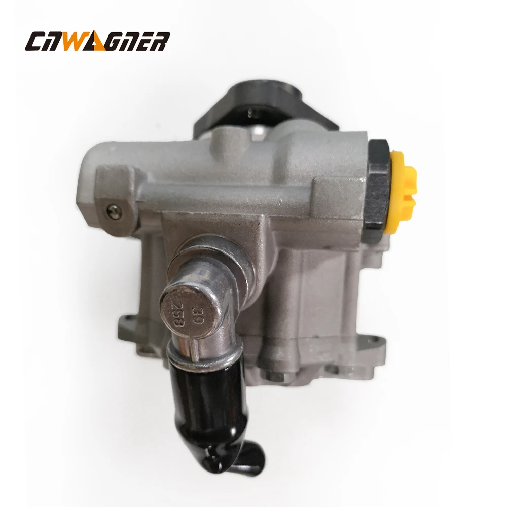
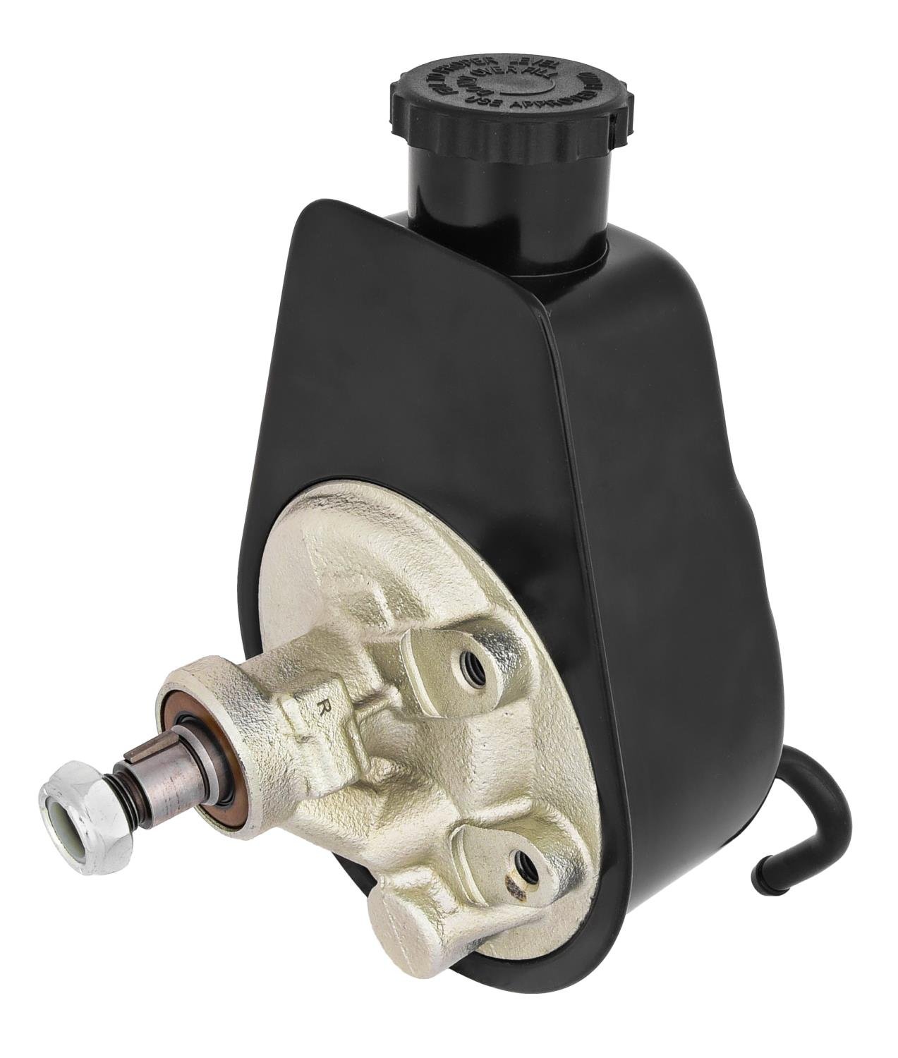
The steering pump has the size of about a coconut, and you can usually find it attached next to your car’s engine. If you want to have a look, just follow along the engine belt and you will eventually see it.
Although power steering pump is metaphorically known as the “heart” of our power steering system, it is just a drop of water in the ocean. There are a myriad of other mechanisms surrounding and supporting it so that the whole system ticks. With that being said, it can get very complicated very fast, especially if one is unfamiliar with the power steering system as a whole.
In that spirit, we’ve simplified “how power steering pump works” into three sections to ease you through the process. These sections are (i) before steering pump, (ii) within steering pump, and (iii) after steering pump.
If you open up your car hood, you will find a (usually) yellow-ish container that has the word “power steering fluid” written on the cap. It is the container where we pour our steering fluid into.
The sole purpose of this tank is just to hold the steering fluid and supplies them to the steering pump through a set of rubber hoses. When we are not using the fluid, it rests in the reservoir. When we need the steering fluid, it gets sucked out of this reservoir into wherever it needs to go.
Now, we need to get the steering pump spinning first. In order to crank it, we need a continuous supply of power going to the pump, and that comes from none other than the car engine itself.
Our car engine produces power by igniting petrol-air mixture with electrical sparks. When the petrol-air mixture explodes inside the engine, it produces energy that pushes the engine piston up and down. And because our engine piston is mechanically connected to the crankshaft, the crankshaft harvests these energy and the crankshaft itself starts to rotate.
Finally, we put an engine belt around this rotating crankshaft, and connects it firmly to the pulley on the steering pump.When we start our car, the engine belt pulls onto the steering pump pulley and the steering pump starts spinning.
At this stage, we got the steering pump spinning, and the steering fluid readily available to the pump. The next step, is to pressurize the steering fluid.
Here comes the exciting part. We will now take a peek at the core of a steering pump to help understand how this majestic device creates high pressure fluid.
The picture above is what you would typically see inside a power steering pump. Granted, not all steering pump looks like this, and there are other intricacies here and there that we took out, but let’s keep it real simple here. There are only 3 distinct items that you really need to pay attention to, namely the (i) housing, (ii) rotor, and (iii) vane.
The rotor is this solid metal block that has only two distinct features: it has a hollow hole in the middle, and then some cavities on the exterior. Both serve a different purpose.
The center hole connects directly to the steering pump pulley through another cylindrical metal. So if you can imagine, when the steering pump pulley is rotating, the rotor itself will consequently rotates as well, and hence the name “rotor”.
Remember the cavities on the exterior? These tiny pocket of holes are where the vanes will rests. They act as a railway for the vanes to be moving in and out. When the steering pump is not rotating, they rests closer to the center (see left picture below). When the rotor rotates, all the vanes get pushed outward and against the pump housing (see right picture below).
Well, it’s like playing with a carousel at the kid’s playground. You can find a comfortable place to sit on the carousel, and then get a friend to spin you like crazy! The faster he spins, the more you will feel like you are being thrown outward. If he spins hard enough, you may just end up amongst the mud!
Similarly in the power steering pump, all the vanes will be pushed outwards against the pump housing. But that’s not all. Imagine the same centrifugal force, but with engine RPM, which is typically measured in the thousands per minute. The vanes are pushed so strongly against the pump housing, that it starts to form tiny chambers which traps the steering fluid. In our example, there are exactly 11 of the tiny chambers.
As the rotor rotates in a clockwise fashion, the tiny chambers follow along (together with the steering fluid inside of it!). Chamber No.1 will move from it’s original position, into Chamber No.2, then Chamber No.3, and so on and so forth at an incredible speed until we switch off the engine.
If you look closely, the pump housing is not geometrically round, they are designed to be oval in shape, purposefully. When the rotor is placed directly at the center, you will notice that the bottom part of the groove is significantly bigger than the top part of the groove.
When the pump continues to rotate, the steering fluid are carried around the oval groove like a merry-go-round. Because of the eccentric oval shape, the steering fluid moves from a large area, and gets squeezed into an increasingly smaller space. If we look to Physics, we know that when the area decreases, pressure increases. Engineers know what’s up. But hey, don’t take my word for it, I’ll even prove it to you.
First, you blow a balloon until a decent size, then you tie a knot around the openings to seal the air inside. As you squeeze the balloon, the space inside the balloon reduces. With nowhere to escape, the same amount of air gets crammed into a tighter confinement which increases the air pressure. If you squeeze it hard enough, it will reach a point where the air pressure is greater than the strength of the balloon and it finally bursts.
Air acts just like any other fluid, which includes steering fluid. Given the same amount of fluid, when you reduce the area, the fluid pressure will increase. And that is exactly why they designed the cam ring to be oval instead of a perfect round shape.
We talked about how these tiny chambers continually spin the steering fluid into a tighter space to increase the pressure. After that, the high pressure steering fluid eventually exits out of the steering pump through the pressure control valve.
For those who are familiar with Hydraulic Power Steering: What it is and How it Works, you would have a very good idea of how the story ends. For those who don’t, here’s how it basically goes down.
The high pressure steering fluid leaves the steering pump, and into the steering rack. Basically speaking, the steering rack is divided into two hydraulic chambers, the left and the right side.
When the steering fluid enters the two hydraulic chambers, they are distributed in a way that one of the hydraulic chamber in the steering rack gets more steering fluid than the other. If the left chamber gets more fluid, it becomes stronger than the right chamber. And guess what happens? The steering rack pushes to the right thanks to the difference in fluid pressure. The reverse is true when you want to turn to the left.
I sincerely hope that I did justice in dissecting the inner workings of a steering pump and hopefully it helps us better appreciate the marvel of engineering that goes into our car.
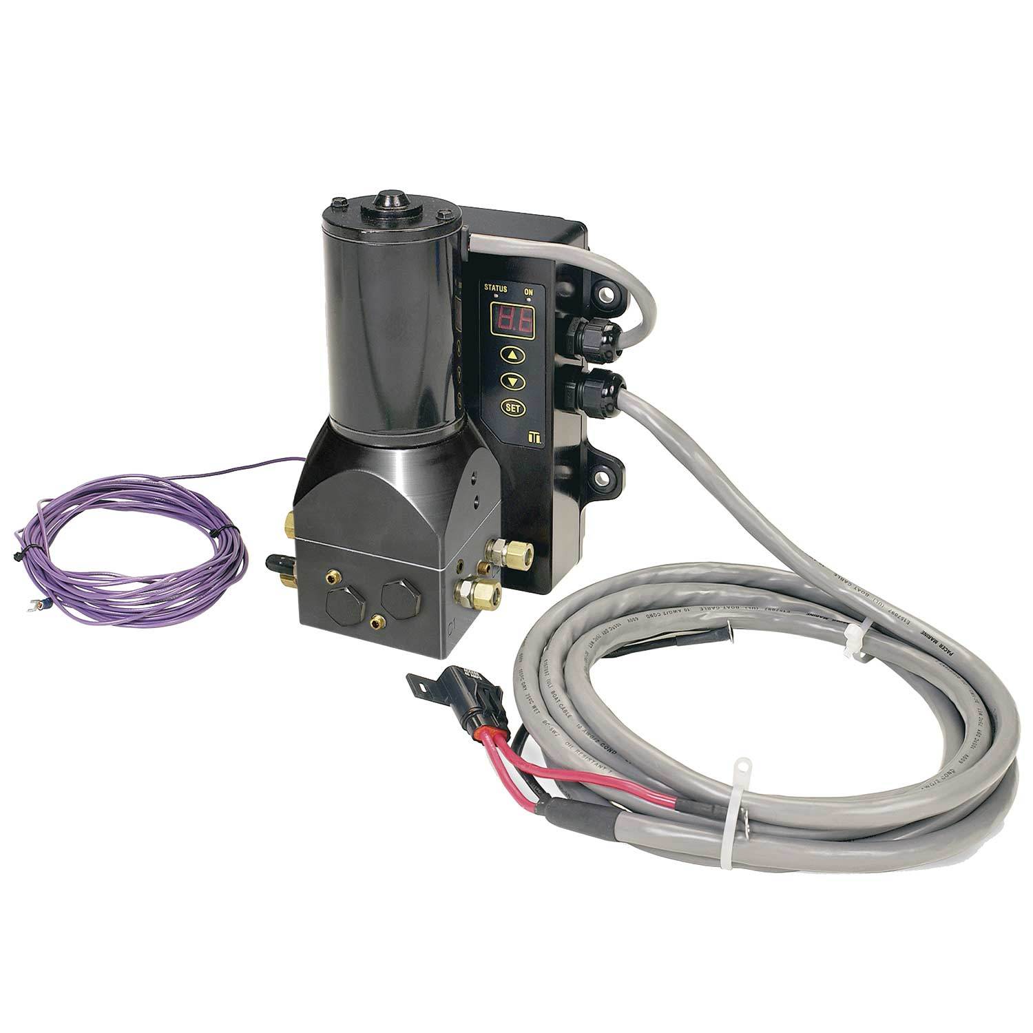
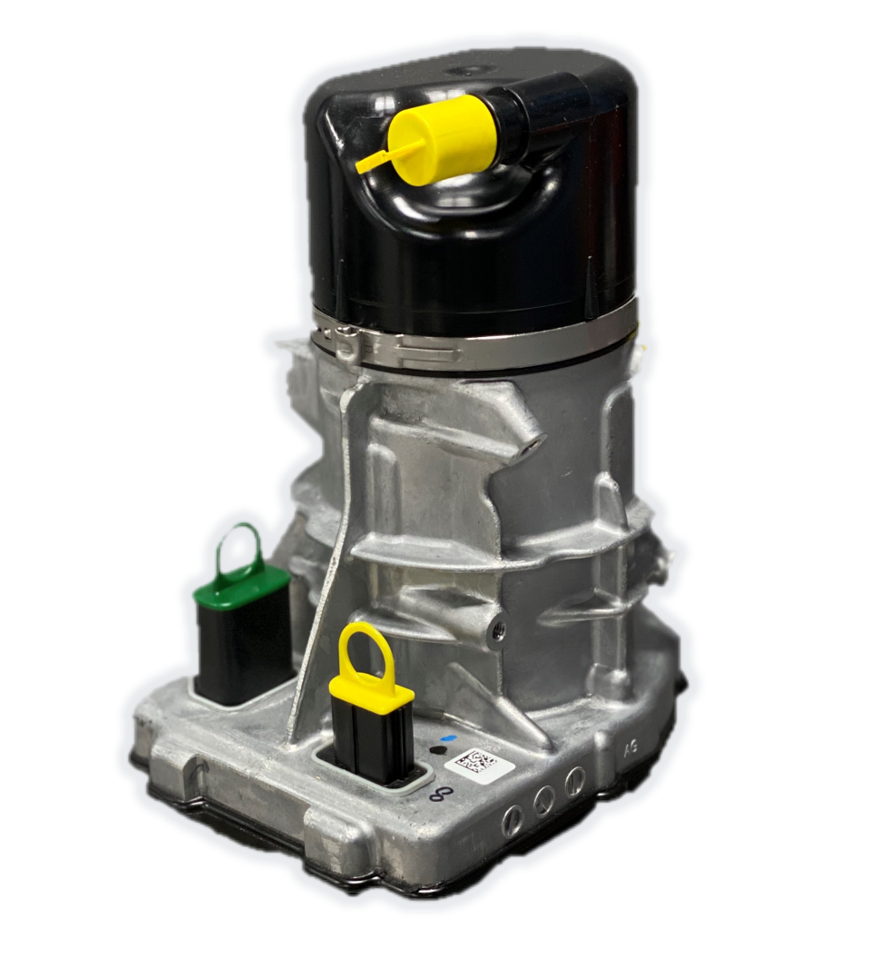
The article in question is described as a hydraulic power steering pump. Based on the information submitted the steering pump is a rotary positive displacement pump for hydraulic fluid. The pump employs vanes to displace hydraulic fluid under pressure and is used in the power steering system of a vehicle. A sample and descriptive literature was submitted. The sample will be returned under separate cover.
The applicable subheading for the power steering pump will be 8413.60.0020, Harmonized Tariff Schedule of the United States (HTSUS), which provides for vane type hydraulic fluid power pumps. The rate of duty is free.

At present, most of the steering pumps for automobiles are double-acting vane type steering pumps, which mainly consist of ordinary double-acting vane pumps, flow control valves, and pressure safety valves; double-acting vane pumps provide high-pressure oil and flow control valves to ensure that the steering pump output is suitable for the flow of the whole vehicle demand, pressure safety valves control the maximum output pressure of the steering pump, for gasoline engines with small engine power, they should also be equipped with pressure switches.
While Pentosin’s signature “green can” is a well-known staple in the hydraulic fluid market, the Pentosin name is well-established across all technical fluid categories in the import vehicle community: antifreeze, brake fluids, hydraulic fluids, motor oil, and transmission fluids.
Pentosin branded products have been trusted by the OE market for many years, with more than 25 “first fill” approvals from Asian and European vehicle manufacturers. By partnering directly with car manufacturers, the Pentosin brand is able to offer unique fluids to meet today’s challenging technical innovations for a wide range of applications.
Copyright © 1998-2020 Focus Technology Co., Ltd. All Rights Reserved. Terms & Conditions Declaration Privacy Policy Technical support: chongqing betweeneastwest technology co., LTD

Copyright © 1998-2020 Focus Technology Co., Ltd. All Rights Reserved. Terms & Conditions Declaration Privacy Policy Technical support: chongqing betweeneastwest technology co., LTD

This website is using a security service to protect itself from online attacks. The action you just performed triggered the security solution. There are several actions that could trigger this block including submitting a certain word or phrase, a SQL command or malformed data.
This product carries our 12 Month Limited Warranty. All warranties are limited to the original purchaser and are not transferable to subsequent owners of the product. The warranty period begins on the purchase date.
Specifically excluded from this warranty are failures caused by lack of maintenance, misuse, negligence, modification, abuse, improper application, crash damage, installation or operation, or failures caused by unauthorized service or use of unauthorized parts.
Additionally excluded from this warranty are parts which are subject to normal wear and tear, such as bushings, fluids, hoses, gaskets, belts, etc. Products not manufactured by Trail-Gear Inc. are excluded from any warranty and shall be handled with the original manufacturer.
All parts used in a competitive racing environment are excluded from this warranty. If, after inspection, a part returned, under any warranty, is deemed to be ineligible for warranty repair or replacement, the part may be repaired or replaced for a discounted cost. Return shipping charges will apply. Any part for which a warranty replacement is sought must be returned to Trail-Gear Inc. before any replacement items can be shipped. All replacement parts shipped before the suspect part has been received and evaluated by Trail-Gear, MUST BE PAID IN FULL. In such a case, after the suspect part has been received and approved for a warranty replacement, the purchase price for the replacement will be refunded.
Please contact Trail-Gear Inc. at 559-252-4950 or email sales@trail-gear.com prior to returning any product(s) under warranty to verify that warranty is still in effect.
Hydraulic pumps are mechanisms in hydraulic systems that move hydraulic fluid from point to point initiating the production of hydraulic power. Hydraulic pumps are sometimes incorrectly referred to as “hydrolic” pumps.
They are an important device overall in the hydraulics field, a special kind of power transmission which controls the energy which moving fluids transmit while under pressure and change into mechanical energy. Other kinds of pumps utilized to transmit hydraulic fluids could also be referred to as hydraulic pumps. There is a wide range of contexts in which hydraulic systems are applied, hence they are very important in many commercial, industrial, and consumer utilities.
“Power transmission” alludes to the complete procedure of technologically changing energy into a beneficial form for practical applications. Mechanical power, electrical power, and fluid power are the three major branches that make up the power transmission field. Fluid power covers the usage of moving gas and moving fluids for the transmission of power. Hydraulics are then considered as a sub category of fluid power that focuses on fluid use in opposition to gas use. The other fluid power field is known as pneumatics and it’s focused on the storage and release of energy with compressed gas.
"Pascal"s Law" applies to confined liquids. Thus, in order for liquids to act hydraulically, they must be contained within a system. A hydraulic power pack or hydraulic power unit is a confined mechanical system that utilizes liquid hydraulically. Despite the fact that specific operating systems vary, all hydraulic power units share the same basic components. A reservoir, valves, a piping/tubing system, a pump, and actuators are examples of these components. Similarly, despite their versatility and adaptability, these mechanisms work together in related operating processes at the heart of all hydraulic power packs.
The hydraulic reservoir"s function is to hold a volume of liquid, transfer heat from the system, permit solid pollutants to settle, and aid in releasing moisture and air from the liquid.
Mechanical energy is changed to hydraulic energy by the hydraulic pump. This is accomplished through the movement of liquid, which serves as the transmission medium. All hydraulic pumps operate on the same basic principle of dispensing fluid volume against a resistive load or pressure.
Hydraulic valves are utilized to start, stop, and direct liquid flow in a system. Hydraulic valves are made of spools or poppets and can be actuated hydraulically, pneumatically, manually, electrically, or mechanically.
The end result of Pascal"s law is hydraulic actuators. This is the point at which hydraulic energy is transformed back to mechanical energy. This can be accomplished by using a hydraulic cylinder to transform hydraulic energy into linear movement and work or a hydraulic motor to transform hydraulic energy into rotational motion and work. Hydraulic motors and hydraulic cylinders, like hydraulic pumps, have various subtypes, each meant for specific design use.
The essence of hydraulics can be found in a fundamental physical fact: fluids are incompressible. (As a result, fluids more closely resemble solids than compressible gasses) The incompressible essence of fluid allows it to transfer force and speed very efficiently. This fact is summed up by a variant of "Pascal"s Principle," which states that virtually all pressure enforced on any part of a fluid is transferred to every other part of the fluid. This scientific principle states, in other words, that pressure applied to a fluid transmits equally in all directions.
Furthermore, the force transferred through a fluid has the ability to multiply as it moves. In a slightly more abstract sense, because fluids are incompressible, pressurized fluids should keep a consistent pressure just as they move. Pressure is defined mathematically as a force acting per particular area unit (P = F/A). A simplified version of this equation shows that force is the product of area and pressure (F = P x A). Thus, by varying the size or area of various parts inside a hydraulic system, the force acting inside the pump can be adjusted accordingly (to either greater or lesser). The need for pressure to remain constant is what causes force and area to mirror each other (on the basis of either shrinking or growing). A hydraulic system with a piston five times larger than a second piston can demonstrate this force-area relationship. When a force (e.g., 50lbs) is exerted on the smaller piston, it is multiplied by five (e.g., 250 lbs) and transmitted to the larger piston via the hydraulic system.
Hydraulics is built on fluids’ chemical properties and the physical relationship between pressure, area, and force. Overall, hydraulic applications allow human operators to generate and exert immense mechanical force with little to no physical effort. Within hydraulic systems, both oil and water are used to transmit power. The use of oil, on the other hand, is far more common, owing in part to its extremely incompressible nature.
Pressure relief valves prevent excess pressure by regulating the actuators’ output and redirecting liquid back to the reservoir when necessary. Directional control valves are used to change the size and direction of hydraulic fluid flow.
While hydraulic power transmission is remarkably useful in a wide range of professional applications, relying solely on one type of power transmission is generally unwise. On the contrary, the most efficient strategy is to combine a wide range of power transmissions (pneumatic, hydraulic, mechanical, and electrical). As a result, hydraulic systems must be carefully embedded into an overall power transmission strategy for the specific commercial application. It is necessary to invest in locating trustworthy and skilled hydraulic manufacturers/suppliers who can aid in the development and implementation of an overall hydraulic strategy.
The intended use of a hydraulic pump must be considered when selecting a specific type. This is significant because some pumps may only perform one function, whereas others allow for greater flexibility.
The pump"s material composition must also be considered in the application context. The cylinders, pistons, and gears are frequently made of long-lasting materials like aluminum, stainless steel, or steel that can withstand the continuous wear of repeated pumping. The materials must be able to withstand not only the process but also the hydraulic fluids. Composite fluids frequently contain oils, polyalkylene glycols, esters, butanol, and corrosion inhibitors (though water is used in some instances). The operating temperature, flash point, and viscosity of these fluids differ.
In addition to material, manufacturers must compare hydraulic pump operating specifications to make sure that intended utilization does not exceed pump abilities. The many variables in hydraulic pump functionality include maximum operating pressure, continuous operating pressure, horsepower, operating speed, power source, pump weight, and maximum fluid flow. Standard measurements like length, rod extension, and diameter should be compared as well. Because hydraulic pumps are used in lifts, cranes, motors, and other heavy machinery, they must meet strict operating specifications.
It is critical to recall that the overall power generated by any hydraulic drive system is influenced by various inefficiencies that must be considered in order to get the most out of the system. The presence of air bubbles within a hydraulic drive, for example, is known for changing the direction of the energy flow inside the system (since energy is wasted on the way to the actuators on bubble compression). Using a hydraulic drive system requires identifying shortfalls and selecting the best parts to mitigate their effects. A hydraulic pump is the "generator" side of a hydraulic system that initiates the hydraulic procedure (as opposed to the "actuator" side that completes the hydraulic procedure). Regardless of disparities, all hydraulic pumps are responsible for displacing liquid volume and transporting it to the actuator(s) from the reservoir via the tubing system. Some form of internal combustion system typically powers pumps.
While the operation of hydraulic pumps is normally the same, these mechanisms can be split into basic categories. There are two types of hydraulic pumps to consider: gear pumps and piston pumps. Radial and axial piston pumps are types of piston pumps. Axial pumps produce linear motion, whereas radial pumps can produce rotary motion. The gear pump category is further subdivided into external gear pumps and internal gear pumps.
Each type of hydraulic pump, regardless of piston or gear, is either double-action or single-action. Single-action pumps can only pull, push, or lift in one direction, while double-action pumps can pull, push, or lift in multiple directions.
Vane pumps are positive displacement pumps that maintain a constant flow rate under varying pressures. It is a pump that self-primes. It is referred to as a "vane pump" because the effect of the vane pressurizes the liquid.
This pump has a variable number of vanes mounted onto a rotor that rotates within the cavity. These vanes may be variable in length and tensioned to maintain contact with the wall while the pump draws power. The pump also features a pressure relief valve, which prevents pressure rise inside the pump from damaging it.
Internal gear pumps and external gear pumps are the two main types of hydraulic gear pumps. Pumps with external gears have two spur gears, the spurs of which are all externally arranged. Internal gear pumps also feature two spur gears, and the spurs of both gears are internally arranged, with one gear spinning around inside the other.
Both types of gear pumps deliver a consistent amount of liquid with each spinning of the gears. Hydraulic gear pumps are popular due to their versatility, effectiveness, and fairly simple design. Furthermore, because they are obtainable in a variety of configurations, they can be used in a wide range of consumer, industrial, and commercial product contexts.
Hydraulic ram pumps are cyclic machines that use water power, also referred to as hydropower, to transport water to a higher level than its original source. This hydraulic pump type is powered solely by the momentum of moving or falling water.
Ram pumps are a common type of hydraulic pump, especially among other types of hydraulic water pumps. Hydraulic ram pumps are utilized to move the water in the waste management, agricultural, sewage, plumbing, manufacturing, and engineering industries, though only about ten percent of the water utilized to run the pump gets to the planned end point.
Despite this disadvantage, using hydropower instead of an external energy source to power this kind of pump makes it a prominent choice in developing countries where the availability of the fuel and electricity required to energize motorized pumps is limited. The use of hydropower also reduces energy consumption for industrial factories and plants significantly. Having only two moving parts is another advantage of the hydraulic ram, making installation fairly simple in areas with free falling or flowing water. The water amount and the rate at which it falls have an important effect on the pump"s success. It is critical to keep this in mind when choosing a location for a pump and a water source. Length, size, diameter, minimum and maximum flow rates, and speed of operation are all important factors to consider.
Hydraulic water pumps are machines that move water from one location to another. Because water pumps are used in so many different applications, there are numerous hydraulic water pump variations.
Water pumps are useful in a variety of situations. Hydraulic pumps can be used to direct water where it is needed in industry, where water is often an ingredient in an industrial process or product. Water pumps are essential in supplying water to people in homes, particularly in rural residences that are not linked to a large sewage circuit. Water pumps are required in commercial settings to transport water to the upper floors of high rise buildings. Hydraulic water pumps in all of these situations could be powered by fuel, electricity, or even by hand, as is the situation with hydraulic hand pumps.
Water pumps in developed economies are typically automated and powered by electricity. Alternative pumping tools are frequently used in developing economies where dependable and cost effective sources of electricity and fuel are scarce. Hydraulic ram pumps, for example, can deliver water to remote locations without the use of electricity or fuel. These pumps rely solely on a moving stream of water’s force and a properly configured number of valves, tubes, and compression chambers.
Electric hydraulic pumps are hydraulic liquid transmission machines that use electricity to operate. They are frequently used to transfer hydraulic liquid from a reservoir to an actuator, like a hydraulic cylinder. These actuation mechanisms are an essential component of a wide range of hydraulic machinery.
There are several different types of hydraulic pumps, but the defining feature of each type is the use of pressurized fluids to accomplish a job. The natural characteristics of water, for example, are harnessed in the particular instance of hydraulic water pumps to transport water from one location to another. Hydraulic gear pumps and hydraulic piston pumps work in the same way to help actuate the motion of a piston in a mechanical system.
Despite the fact that there are numerous varieties of each of these pump mechanisms, all of them are powered by electricity. In such instances, an electric current flows through the motor, which turns impellers or other devices inside the pump system to create pressure differences; these differential pressure levels enable fluids to flow through the pump. Pump systems of this type can be utilized to direct hydraulic liquid to industrial machines such as commercial equipment like elevators or excavators.
Hydraulic hand pumps are fluid transmission machines that utilize the mechanical force generated by a manually operated actuator. A manually operated actuator could be a lever, a toggle, a handle, or any of a variety of other parts. Hydraulic hand pumps are utilized for hydraulic fluid distribution, water pumping, and various other applications.
Hydraulic hand pumps may be utilized for a variety of tasks, including hydraulic liquid direction to circuits in helicopters and other aircraft, instrument calibration, and piston actuation in hydraulic cylinders. Hydraulic hand pumps of this type use manual power to put hydraulic fluids under pressure. They can be utilized to test the pressure in a variety of devices such as hoses, pipes, valves, sprinklers, and heat exchangers systems. Hand pumps are extraordinarily simple to use.
Each hydraulic hand pump has a lever or other actuation handle linked to the pump that, when pulled and pushed, causes the hydraulic liquid in the pump"s system to be depressurized or pressurized. This action, in the instance of a hydraulic machine, provides power to the devices to which the pump is attached. The actuation of a water pump causes the liquid to be pulled from its source and transferred to another location. Hydraulic hand pumps will remain relevant as long as hydraulics are used in the commerce industry, owing to their simplicity and easy usage.
12V hydraulic pumps are hydraulic power devices that operate on 12 volts DC supplied by a battery or motor. These are specially designed processes that, like all hydraulic pumps, are applied in commercial, industrial, and consumer places to convert kinetic energy into beneficial mechanical energy through pressurized viscous liquids. This converted energy is put to use in a variety of industries.
Hydraulic pumps are commonly used to pull, push, and lift heavy loads in motorized and vehicle machines. Hydraulic water pumps may also be powered by 12V batteries and are used to move water out of or into the desired location. These electric hydraulic pumps are common since they run on small batteries, allowing for ease of portability. Such portability is sometimes required in waste removal systems and vehiclies. In addition to portable and compact models, options include variable amp hour productions, rechargeable battery pumps, and variable weights.
While non rechargeable alkaline 12V hydraulic pumps are used, rechargeable ones are much more common because they enable a continuous flow. More considerations include minimum discharge flow, maximum discharge pressure, discharge size, and inlet size. As 12V batteries are able to pump up to 150 feet from the ground, it is imperative to choose the right pump for a given use.
Air hydraulic pumps are hydraulic power devices that use compressed air to stimulate a pump mechanism, generating useful energy from a pressurized liquid. These devices are also known as pneumatic hydraulic pumps and are applied in a variety of industries to assist in the lifting of heavy loads and transportation of materials with minimal initial force.
Air pumps, like all hydraulic pumps, begin with the same components. The hydraulic liquids, which are typically oil or water-based composites, require the use of a reservoir. The fluid is moved from the storage tank to the hydraulic cylinder via hoses or tubes connected to this reservoir. The hydraulic cylinder houses a piston system and two valves. A hydraulic fluid intake valve allows hydraulic liquid to enter and then traps it by closing. The discharge valve is the point at which the high pressure fluid stream is released. Air hydraulic pumps have a linked air cylinder in addition to the hydraulic cylinder enclosing one end of the piston.
The protruding end of the piston is acted upon by a compressed air compressor or air in the cylinder. When the air cylinder is empty, a spring system in the hydraulic cylinder pushes the piston out. This makes a vacuum, which sucks fluid from the reservoir into the hydraulic cylinder. When the air compressor is under pressure, it engages the piston and pushes it deeper into the hydraulic cylinder and compresses the liquids. This pumping action is repeated until the hydraulic cylinder pressure is high enough to forcibly push fluid out through the discharge check valve. In some instances, this is connected to a nozzle and hoses, with the important part being the pressurized stream. Other uses apply the energy of this stream to pull, lift, and push heavy loads.
Hydraulic piston pumps transfer hydraulic liquids through a cylinder using plunger-like equipment to successfully raise the pressure for a machine, enabling it to pull, lift, and push heavy loads. This type of hydraulic pump is the power source for heavy-duty machines like excavators, backhoes, loaders, diggers, and cranes. Piston pumps are used in a variety of industries, including automotive, aeronautics, power generation, military, marine, and manufacturing, to mention a few.
Hydraulic piston pumps are common due to their capability to enhance energy usage productivity. A hydraulic hand pump energized by a hand or foot pedal can convert a force of 4.5 pounds into a load-moving force of 100 pounds. Electric hydraulic pumps can attain pressure reaching 4,000 PSI. Because capacities vary so much, the desired usage pump must be carefully considered. Several other factors must also be considered. Standard and custom configurations of operating speeds, task-specific power sources, pump weights, and maximum fluid flows are widely available. Measurements such as rod extension length, diameter, width, and height should also be considered, particularly when a hydraulic piston pump is to be installed in place of a current hydraulic piston pump.
Hydraulic clutch pumps are mechanisms that include a clutch assembly and a pump that enables the user to apply the necessary pressure to disengage or engage the clutch mechanism. Hydraulic clutches are crafted to either link two shafts and lock them together to rotate at the same speed or detach the shafts and allow them to rotate at different speeds as needed to decelerate or shift gears.
Hydraulic pumps change hydraulic energy to mechanical energy. Hydraulic pumps are particularly designed machines utilized in commercial, industrial, and residential areas to generate useful energy from different viscous liquids pressurization. Hydraulic pumps are exceptionally simple yet effective machines for moving fluids. "Hydraulic" is actually often misspelled as "Hydralic". Hydraulic pumps depend on the energy provided by hydraulic cylinders to power different machines and mechanisms.
There are several different types of hydraulic pumps, and all hydraulic pumps can be split into two primary categories. The first category includes hydraulic pumps that function without the assistance of auxiliary power sources such as electric motors and gas. These hydraulic pump types can use the kinetic energy of a fluid to transfer it from one location to another. These pumps are commonly called ram pumps. Hydraulic hand pumps are never regarded as ram pumps, despite the fact that their operating principles are similar.
The construction, excavation, automotive manufacturing, agriculture, manufacturing, and defense contracting industries are just a few examples of operations that apply hydraulics power in normal, daily procedures. Since hydraulics usage is so prevalent, hydraulic pumps are unsurprisingly used in a wide range of machines and industries. Pumps serve the same basic function in all contexts where hydraulic machinery is used: they transport hydraulic fluid from one location to another in order to generate hydraulic energy and pressure (together with the actuators).
Elevators, automotive brakes, automotive lifts, cranes, airplane flaps, shock absorbers, log splitters, motorboat steering systems, garage jacks and other products use hydraulic pumps. The most common application of hydraulic pumps in construction sites is in big hydraulic machines and different types of "off-highway" equipment such as excavators, dumpers, diggers, and so on. Hydraulic systems are used in other settings, such as offshore work areas and factories, to power heavy machinery, cut and bend material, move heavy equipment, and so on.
Fluid’s incompressible nature in hydraulic systems allows an operator to make and apply mechanical power in an effective and efficient way. Practically all force created in a hydraulic system is applied to the intended target.
Because of the relationship between area, pressure, and force (F = P x A), modifying the force of a hydraulic system is as simple as changing the size of its components.
Hydraulic systems can transfer energy on an equal level with many mechanical and electrical systems while being significantly simpler in general. A hydraulic system, for example, can easily generate linear motion. On the contrary, most electrical and mechanical power systems need an intermediate mechanical step to convert rotational motion to linear motion.
Hydraulic systems are typically smaller than their mechanical and electrical counterparts while producing equivalents amounts of power, providing the benefit of saving physical space.
Hydraulic systems can be used in a wide range of physical settings due to their basic design (a pump attached to actuators via some kind of piping system). Hydraulic systems could also be utilized in environments where electrical systems would be impractical (for example underwater).
By removing electrical safety hazards, using hydraulic systems instead of electrical power transmission improves relative safety (for example explosions, electric shock).
The amount of power that hydraulic pumps can generate is a significant, distinct advantage. In certain cases, a hydraulic pump could generate ten times the power of an electrical counterpart. Some hydraulic pumps (for example, piston pumps) cost more than the ordinary hydraulic component. These drawbacks, however, can be mitigated by the pump"s power and efficiency. Despite their relatively high cost, piston pumps are treasured for their strength and capability to transmit very viscous fluids.
Handling hydraulic liquids is messy, and repairing leaks in a hydraulic pump can be difficult. Hydraulic liquid that leaks in hot areas may catch fire. Hydraulic lines that burst may cause serious injuries. Hydraulic liquids are corrosive as well, though some are less so than others. Hydraulic systems need frequent and intense maintenance. Parts with a high factor of precision are frequently required in systems. If the power is very high and the pipeline cannot handle the power transferred by the liquid, the high pressure received by the liquid may also cause work accidents.
Even though hydraulic systems are less complex than electrical or mechanical systems, they are still complex systems that should be handled with caution. Avoiding physical contact with hydraulic systems is an essential safety precaution when engaging with them. Even when a hydraulic machine is not in use, active liquid pressure within the system can be a hazard.
Inadequate pumps can cause mechanical failure in the place of work that can have serious and costly consequences. Although pump failure has historically been unpredictable, new diagnostic technology continues to improve on detecting methods that previously relied solely on vibration signals. Measuring discharge pressures enables manufacturers to forecast pump wear more accurately. Discharge sensors are simple to integrate into existing systems, increasing the hydraulic pump"s safety and versatility.
Hydraulic pumps are devices in hydraulic systems that move hydraulic fluid from point to point, initiating hydraulic power production. They are an important device overall in the hydraulics field, a special kind of power transmission that controls the energy which moving fluids transmit while under pressure and change into mechanical energy. Hydraulic pumps are divided into two categories namely gear pumps and piston pumps. Radial and axial piston pumps are types of piston pumps. Axial pumps produce linear motion, whereas radial pumps can produce rotary motion. The construction, excavation, automotive manufacturing, agriculture, manufacturing, and defense contracting industries are just a few examples of operations that apply hydraulics power in normal, daily procedures.

A power steering is a mechanical device equipped on a motor vehicle that helps drivers steer the vehicle by reducing steering effort needed to turn the steering wheel, making it easier for the vehicle to turn or maneuver at lower speeds.
Hydraulic or electric actuators add controlled energy to the steering mechanism, so the driver can provide less effort to turn the steered wheels when driving at typical speeds, and reduce considerably the physical effort necessary to turn the wheels when a vehicle is stopped or moving slowly. Power steering can also be engineered to provide some artificial feedback of forces acting on the steered wheels.
Hydraulic power steering systems for cars augment steering effort via an actuator, a hydraulic cylinder that is part of a servo system. These systems have a direct mechanical connection between the steering wheel and the linkage that steers the wheels. This means that power-steering system failure (to augment effort) still permits the vehicle to be steered using manual effort alone.
Electric power steering systems use electric motors to provide the assistance instead of hydraulic systems. As with hydraulic types, power to the actuator (motor, in this case) is controlled by the rest of the power steering system.
Other power steering systems (such as those in the largest off-road construction vehicles) have no direct mechanical connection to the steering linkage; they require electrical power. Systems of this kind, with no mechanical connection, are sometimes called "drive by wire" or "steer by wire", by analogy with aviation"s "fly-by-wire". In this context, "wire" refers to electrical cables that carry power and data, not thin wire rope mechanical control cables.
Some construction vehicles have a two-part frame with a rugged hinge in the middle; this hinge allows the front and rear axles to become non-parallel to steer the vehicle. Opposing hydraulic cylinders move the halves of the frame relative to each other to steer.
The first power steering system on a vehicle was apparently installed in 1876 by a man with the surname of Fitts, but little else is known about him.electric motor was used to assist the driver in turning the front wheels.
Francis W. Davis, an engineer of the truck division of Pierce-Arrow, began exploring how steering could be made easier, and in 1926 invented and demonstrated the first practical power steering system.General Motors and refined the hydraulic-assisted power steering system, but the automaker calculated it would be too expensive to produce.Bendix, a parts manufacturer for automakers. Military needs during World War II for easier steering on heavy vehicles boosted the need for power assistance on armored cars and tank-recovery vehicles for the British and American armies.
Chrysler Corporation introduced the first commercially available passenger car power steering system on the 1951 Chrysler Imperial under the name "Hydraguide".Cadillac with a power steering system using the work Davis had done for the company almost twenty years earlier.
Starting in the mid-1950s American manufacturers offered the technology as optional or standard equipment while it is widely offered internationally on modern vehicles, owing to the trends toward front-wheel drive, greater vehicle mass, reduced assembly line production costs, and wider tires, which all increase the required steering effort. Heavier vehicles, as are common in some countries, would be extremely difficult to maneuver at low speeds, while vehicles of lighter weight may not need power assisted steering at all.
A study in 1999 on the perceptual fidelity of steering force feedback, found that ordinary real-world truck and car drivers naturally expect an increase in feedback torque as speed increases, and for this reason early forms of power steering, which lacked such effect, were met with disapproval.
Hydraulic power steering systems work by using a hydraulic system to multiply force applied to the steering wheel inputs to the vehicle"s steered (usually front) road wheels.gerotor or rotary vane pump driven by the vehicle"s engine. A double-acting hydraulic cylinder applies a force to the steering gear, which in turn steers the roadwheels. The steering wheel operates valves to control flow to the cylinder. The more torque the driver applies to the steering wheel and column, the more fluid the valves allow through to the cylinder, and so the more force is applied to steer the wheels.
One design for measuring the torque applied to the steering wheel has a torque sensor – a torsion bar at the lower end of the steering column. As the steering wheel rotates, so does the steering column, as well as the upper end of the torsion bar. Since the torsion bar is relatively thin and flexible, and the bottom end usually resists being rotated, the bar will twist by an amount proportional to the applied torque. The difference in position between the opposite ends of the torsion bar controls a valve. The valve allows fluid to flow to the cylinder which provides steering assistance; the greater the "twist" of the torsion bar, the greater the force.
Since the hydraulic pumps are positive-displacement type, the flow rate they deliver is directly proportional to the speed of the engine. This means that at high engine speeds the steering would naturally operate faster than at low engine speeds. Because this would be undesirable, a restricting orifice and flow-control valve direct some of the pump"s output back to the hydraulic reservoir at high engine speeds. A pressure relief valve prevents a dangerous build-up of pressure when the hydraulic cylinder"s piston reaches the end of its stroke.
The steering booster is arranged so that should the booster fail, the steering will continue to work (although the wheel will feel heavier). Loss of power steering can significantly affect the handling of a vehicle. Each vehicle owner"s manual gives instructions for inspection of fluid levels and regular maintenance of the power steering system.
The working liquid, also called "hydraulic fluid" or "oil", is the medium by which pressure is transmitted. Common working liquids are based on mineral oil.
Some modern systems also include an electronic control valve to reduce the hydraulic supply pressure as the vehicle"s speed increases; this is variable-assist power steering.
In this power steering system, the force steering the wheels comes from the car"s high pressure hydraulic system and is always the same no matter what the road speed is. Turning the steering wheel moves the wheels simultaneously to a corresponding angle via a hydraulic cylinder. In order to give some artificial steering feel, there is a separate hydraulically operated system that tries to turn the steering wheel back to centre position. The amount of pressure applied is proportional to road speed, so that at low speeds the steering is very light, and at high speeds it is very difficult to move more than a small amount off centre.
As long as there is pressure in the car"s hydraulic system, there is no mechanical connection between the steering wheel and the roadwheels. This system was first introduced in the Citroën SM in 1970, and was known as "VariPower" in the UK and "SpeedFeel" in the U.S.
Electro-hydraulic power steering systems, sometimes abbreviated EHPS, and also sometimes called "hybrid" systems, use the same hydraulic assist technology as standard systems, but the hydraulic pressure comes from a pump driven by an electric motor instead of a drive belt at the engine.
In 1965, Ford experimented with a fleet of "wrist-twist instant steering" equipped Mercury Park Lanes that replaced the conventional large steering wheel with two 5-inch (127 mm) rings, a fast 15:1 gear ratio, and an electric hydraulic pump in case the engine stalled.
In 1988, the Subaru XT6 was fitted with a unique Cybrid adaptive electro-hydraulic steering system that changed the level of assistance based on the vehicle"s speed.
In 1990, Toyota introduced its second-generation MR2 with electro-hydraulic power steering. This avoided running hydraulic lines from the engine (which was behind the driver in the MR2) up to the steering rack.
In 1994 Volkswagen produced the Golf Mk3 Ecomatic, with an electric pump. This meant that the power steering would still operate while the engine was stopped by the computer to save fuel.Ford, Volkswagen, Audi, Peugeot, Citroën, SEAT, Škoda, Suzuki, Opel, MINI, Toyota, Honda, and Mazda.
Electric power steering (EPS) or motor-driven power steering (MDPS) uses an electric motor instead of a hydraulic system to assist the driver of the vehicle. Sensors detect the position and torque exerted inside the steering column, and a computer module applies assistive torque via the motor, which connects either to the steering gear or steering column. This allows varied amounts of assistance to be applied depending on driving conditions. Engineers can therefore tailor steering-gear response to variable-rate and variable-damping suspension systems, optimizing ride, handling, and steering for each vehicle.
A mechanical linkage between the steering wheel and the steering gear is retained in EPS. In the event of component failure or power failure that causes a failure to provide assistance, the mechanical linkage serves as a back-up. If EPS fails, the driver encounters a situation where heavy effort is required to steer. This heavy effort is similar to that of an inoperative hydraulic steering assist systemsteering ratios in assisted steering gears vs. fully manual. The NHTSA has assisted car manufacturers with recalling EPS systems prone to failure.
Electric systems have an advantage in fuel efficiency because there is no belt-driven hydraulic pump constantly running, whether assistance is required or not, and this is a major reason for their introduction. Another major advantage is the elimination of a belt-driven engine accessory, and several high-pressure hydraulic hoses between the hydraulic pump, mounted on the engine, and the steering gear, mounted on the chassis. This greatly simplifies manufacturing and maintenance. By incorporating electronic stability control electric power steering systems can instantly vary torque assist levels to aid the driver in corrective maneuvers.
Other electric power steering systems (including 4WS) later appeared on the Honda NSX after 1990, the Honda Prelude and the Subaru SVX in 1991, the Nissan 300ZX (Z32; after the Version 3 onwards), Silvia, Skyline, and the Laurel in 1993, the MG F, the FIAT Punto Mk2 in 1999, the Honda S2000 in 1999, Toyota Prius in 2000, the BMW Z4 in 2002, and the Mazda RX-8 in 2003.
The system has been used by various automobile manufacturers, and most commonly applied for smaller cars to reduce fuel consumption and manufacturing costs
In 2000, the Honda S2000 Type V featured the first electric power variable gear ratio steering (VGS) system.Toyota introduced the "Variable Gear Ratio Steering" (VGRS) system on the Lexus LX 470 and Landcruiser Cygnus, and also incorporated the electronic stability control system to alter steering gear ratios and steering assist levels. In 2003, BMW introduced "active steering" system on the 5 Series.
This system should not be confused with variable assist power steering, which varies steering assist torque, not steering ratios, nor with systems where the gear ratio is only varied as a function of steering angle. These last are more accurately called non-linear types (e.g. Direct-Steer offered by Mercedes-Benz); a plot of steering-wheel position versus axle steering angle is progressively curved (and symmetrical).
Keebler, Jack (May 1986). "So long, hydraulics - the electronic revolution in power steering". Popular Science. 228 (5): 50–56. Retrieved 8 September 2015.
Okamoto, Kenjiro; Chikuma, Isamu; Saito, Naoki; Miyazaki, Hiroya (1 April 1989). "Improvement of Driver"s Feel of Electric Power Steering". SAE Technical Paper 890079. SAE Technical Paper Series. SAE Technical Paper. 1. doi:10.4271/890079. Retrieved 4 October 2019.
Nakayama, T.; Suda, E. (1994). "The present and future of electric power steering". International Journal of Vehicle Design. 15: 243. Retrieved 8 November 2015.

This website is using a security service to protect itself from online attacks. The action you just performed triggered the security solution. There are several actions that could trigger this block including submitting a certain word or phrase, a SQL command or malformed data.


 8613371530291