
power steering pump used as hydraulic pump free sample
This product carries our 12 Month Limited Warranty. All warranties are limited to the original purchaser and are not transferable to subsequent owners of the product. The warranty period begins on the purchase date.
Specifically excluded from this warranty are failures caused by lack of maintenance, misuse, negligence, modification, abuse, improper application, crash damage, installation or operation, or failures caused by unauthorized service or use of unauthorized parts.
Additionally excluded from this warranty are parts which are subject to normal wear and tear, such as bushings, fluids, hoses, gaskets, belts, etc. Products not manufactured by Trail-Gear Inc. are excluded from any warranty and shall be handled with the original manufacturer.
All parts used in a competitive racing environment are excluded from this warranty. If, after inspection, a part returned, under any warranty, is deemed to be ineligible for warranty repair or replacement, the part may be repaired or replaced for a discounted cost. Return shipping charges will apply. Any part for which a warranty replacement is sought must be returned to Trail-Gear Inc. before any replacement items can be shipped. All replacement parts shipped before the suspect part has been received and evaluated by Trail-Gear, MUST BE PAID IN FULL. In such a case, after the suspect part has been received and approved for a warranty replacement, the purchase price for the replacement will be refunded.
Please contact Trail-Gear Inc. at 559-252-4950 or email sales@trail-gear.com prior to returning any product(s) under warranty to verify that warranty is still in effect.
To many, steering pump is just some magical black box that supposedly somehow makes our driving trips much more enjoyable. But how does a power steering pump works exactly?
If you clicked into this article, I bet you want to know more than just the surface. We can help with that. Today, we’re going to dive deep into the world of mechanics, particularly on the inner workings of a steering pump.
In a hydraulic power steering system, we have the steering rack and the steering pump. These two components are like Batman and Robin, Thor and Mjolnir, peanut butter and jelly – basically inseparable. They work together to give us the ability to steer our car, and at the same time, making it easy to do so.
In formal terminology, power steering pump is a centrifugal vane type hydraulic pump that pressurizes steering fluid through high speed rotations in order to create a pressure differential that translates into “power assist” for your car’s steering system.
It’s essentially just a water pump, except with steering fluid. It spins like crazy, pressurizes steering fluid like crazy and then send them to the rest of the steering system so that we can steer like crazy.
Generally speaking, steering rack gives us the actual trajectory changes on our car tyres, meaning the ability to steer our car. On the other hand, steering pump is the one responsible for making the steering wheel feel “light” and easy to turn when we steer.
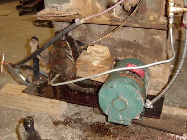
The steering pump has the size of about a coconut, and you can usually find it attached next to your car’s engine. If you want to have a look, just follow along the engine belt and you will eventually see it.
Although power steering pump is metaphorically known as the “heart” of our power steering system, it is just a drop of water in the ocean. There are a myriad of other mechanisms surrounding and supporting it so that the whole system ticks. With that being said, it can get very complicated very fast, especially if one is unfamiliar with the power steering system as a whole.
In that spirit, we’ve simplified “how power steering pump works” into three sections to ease you through the process. These sections are (i) before steering pump, (ii) within steering pump, and (iii) after steering pump.
If you open up your car hood, you will find a (usually) yellow-ish container that has the word “power steering fluid” written on the cap. It is the container where we pour our steering fluid into.
The sole purpose of this tank is just to hold the steering fluid and supplies them to the steering pump through a set of rubber hoses. When we are not using the fluid, it rests in the reservoir. When we need the steering fluid, it gets sucked out of this reservoir into wherever it needs to go.
Now, we need to get the steering pump spinning first. In order to crank it, we need a continuous supply of power going to the pump, and that comes from none other than the car engine itself.
Our car engine produces power by igniting petrol-air mixture with electrical sparks. When the petrol-air mixture explodes inside the engine, it produces energy that pushes the engine piston up and down. And because our engine piston is mechanically connected to the crankshaft, the crankshaft harvests these energy and the crankshaft itself starts to rotate.
Finally, we put an engine belt around this rotating crankshaft, and connects it firmly to the pulley on the steering pump.When we start our car, the engine belt pulls onto the steering pump pulley and the steering pump starts spinning.
At this stage, we got the steering pump spinning, and the steering fluid readily available to the pump. The next step, is to pressurize the steering fluid.
Here comes the exciting part. We will now take a peek at the core of a steering pump to help understand how this majestic device creates high pressure fluid.
The picture above is what you would typically see inside a power steering pump. Granted, not all steering pump looks like this, and there are other intricacies here and there that we took out, but let’s keep it real simple here. There are only 3 distinct items that you really need to pay attention to, namely the (i) housing, (ii) rotor, and (iii) vane.
The rotor is this solid metal block that has only two distinct features: it has a hollow hole in the middle, and then some cavities on the exterior. Both serve a different purpose.
The center hole connects directly to the steering pump pulley through another cylindrical metal. So if you can imagine, when the steering pump pulley is rotating, the rotor itself will consequently rotates as well, and hence the name “rotor”.
Remember the cavities on the exterior? These tiny pocket of holes are where the vanes will rests. They act as a railway for the vanes to be moving in and out. When the steering pump is not rotating, they rests closer to the center (see left picture below). When the rotor rotates, all the vanes get pushed outward and against the pump housing (see right picture below).
Well, it’s like playing with a carousel at the kid’s playground. You can find a comfortable place to sit on the carousel, and then get a friend to spin you like crazy! The faster he spins, the more you will feel like you are being thrown outward. If he spins hard enough, you may just end up amongst the mud!
Similarly in the power steering pump, all the vanes will be pushed outwards against the pump housing. But that’s not all. Imagine the same centrifugal force, but with engine RPM, which is typically measured in the thousands per minute. The vanes are pushed so strongly against the pump housing, that it starts to form tiny chambers which traps the steering fluid. In our example, there are exactly 11 of the tiny chambers.
As the rotor rotates in a clockwise fashion, the tiny chambers follow along (together with the steering fluid inside of it!). Chamber No.1 will move from it’s original position, into Chamber No.2, then Chamber No.3, and so on and so forth at an incredible speed until we switch off the engine.
If you look closely, the pump housing is not geometrically round, they are designed to be oval in shape, purposefully. When the rotor is placed directly at the center, you will notice that the bottom part of the groove is significantly bigger than the top part of the groove.
When the pump continues to rotate, the steering fluid are carried around the oval groove like a merry-go-round. Because of the eccentric oval shape, the steering fluid moves from a large area, and gets squeezed into an increasingly smaller space. If we look to Physics, we know that when the area decreases, pressure increases. Engineers know what’s up. But hey, don’t take my word for it, I’ll even prove it to you.
First, you blow a balloon until a decent size, then you tie a knot around the openings to seal the air inside. As you squeeze the balloon, the space inside the balloon reduces. With nowhere to escape, the same amount of air gets crammed into a tighter confinement which increases the air pressure. If you squeeze it hard enough, it will reach a point where the air pressure is greater than the strength of the balloon and it finally bursts.
Air acts just like any other fluid, which includes steering fluid. Given the same amount of fluid, when you reduce the area, the fluid pressure will increase. And that is exactly why they designed the cam ring to be oval instead of a perfect round shape.
We talked about how these tiny chambers continually spin the steering fluid into a tighter space to increase the pressure. After that, the high pressure steering fluid eventually exits out of the steering pump through the pressure control valve.
For those who are familiar with Hydraulic Power Steering: What it is and How it Works, you would have a very good idea of how the story ends. For those who don’t, here’s how it basically goes down.
The high pressure steering fluid leaves the steering pump, and into the steering rack. Basically speaking, the steering rack is divided into two hydraulic chambers, the left and the right side.
When the steering fluid enters the two hydraulic chambers, they are distributed in a way that one of the hydraulic chamber in the steering rack gets more steering fluid than the other. If the left chamber gets more fluid, it becomes stronger than the right chamber. And guess what happens? The steering rack pushes to the right thanks to the difference in fluid pressure. The reverse is true when you want to turn to the left.
I sincerely hope that I did justice in dissecting the inner workings of a steering pump and hopefully it helps us better appreciate the marvel of engineering that goes into our car.

The article in question is described as a hydraulic power steering pump. Based on the information submitted the steering pump is a rotary positive displacement pump for hydraulic fluid. The pump employs vanes to displace hydraulic fluid under pressure and is used in the power steering system of a vehicle. A sample and descriptive literature was submitted. The sample will be returned under separate cover.
The applicable subheading for the power steering pump will be 8413.60.0020, Harmonized Tariff Schedule of the United States (HTSUS), which provides for vane type hydraulic fluid power pumps. The rate of duty is free.

This product carries our 12 Month Limited Warranty. All warranties are limited to the original purchaser and are not transferable to subsequent owners of the product. The warranty period begins on the purchase date.
Specifically excluded from this warranty are failures caused by lack of maintenance, misuse, negligence, modification, abuse, improper application, crash damage, installation or operation, or failures caused by unauthorized service or use of unauthorized parts.
Additionally excluded from this warranty are parts which are subject to normal wear and tear, such as bushings, fluids, hoses, gaskets, belts, etc. Products not manufactured by Trail-Gear Inc. are excluded from any warranty and shall be handled with the original manufacturer.
All parts used in a competitive racing environment are excluded from this warranty. If, after inspection, a part returned, under any warranty, is deemed to be ineligible for warranty repair or replacement, the part may be repaired or replaced for a discounted cost. Return shipping charges will apply. Any part for which a warranty replacement is sought must be returned to Trail-Gear Inc. before any replacement items can be shipped. All replacement parts shipped before the suspect part has been received and evaluated by Trail-Gear, MUST BE PAID IN FULL. In such a case, after the suspect part has been received and approved for a warranty replacement, the purchase price for the replacement will be refunded.
Please contact Trail-Gear Inc. at 559-252-4950 or email sales@trail-gear.com prior to returning any product(s) under warranty to verify that warranty is still in effect.

This invention relates generally to vehicle mounted winches, and more particularly, to a hydraulic winch utilizing a vehicle steering pump as a source of pressurized hydraulic fluid.
It is well known that hydraulic winches provide a more efficient and lower maintenance alternative to electric winches. Remote-location winch operation is achieved without the inherent reliability problems, limited run time or added size and weight attributable to large electrical power supplies and signal conditioners. Heavy load handling and extended run time operation are provided by a smaller, more efficient and more reliable hydraulic motor.
Typically, hydraulic winch design efforts have been directed at providing a system with specialized functional attributes for specific, primarily commercial applications. For example, Bell, U.S. Pat. No. 5,176,364, discloses a multi-spool assembly driven by a diesel engine. Gravenhurst, U.S. Pat. No. 4,950,125 discloses a crane-mounted winch with disc brakes for better free-fall braking. Hrescak, U.S. Pat. No. 4,227,680, discloses a hydraulic winch utilizing a multiple belt drive configuration for a faster spool rewinding. Peterson, U.S. Pat. No. 4,650,163, discloses a specially designed tractor mount assembly for easier installation. Johnson, U.S. Pat. No. 3,788,605, discloses a spool-enclosed motor and companion bumper mount for more compact passenger car mounting.
Most pertinent to the present invention is Johnson which, while claiming the enclosed motor and mounting configuration, also preliminarily discloses powering the winch with a vehicle hydraulic steering pump. As Johnson notes, the steering pump is, of course, already available. But more importantly, the pump is an ideal source of pressurized fluid for both light and heavy winch operation, utilizing only about one half quart of fluid to provide a low, 2 to 4 gallons per minute fluid volume at a high, 1000 to 1400 p.s.i. of pressure. It also provides a requisite fluid reservoir and pressure relief valve. Johnson further fails to account for such critical considerations as reliable steering system and winch operation, modern vehicle construction, efficiency and, most importantly, operator safety.
First, Johnson provides no means for directing hydraulic fluid for safe and efficient operation of either the steering system or the winch. System-specific containment is critical given the small available volume of fluid. Escaping fluid can cause back-pressure on inactive system startup or even inconsistent or insufficient fluid supply. The consequences include sluggish response or even sudden catastrophic failure, both with potentially disastrous results.
Also, Johnson does not anticipate a means for cooling the hydraulic fluid. Since the hydraulic fluid lubricates internal gears, bearings and other components, fluid overheating and subsequent fluid breakdown could again have disastrous results. The alternative of adding a backup reservoir would complicate and enlarge the assembly.
Additionally, the disclosed control means do not provide for efficient, reliable and safe winch operation. Efficiency is compromised due to the lack of free-spooling capability; for example, motorized reeling out of 100 feet of cable at typically 5 feet per minute requires 20 minutes as opposed to only about one minute of manual reeling. The cabin-mounted lever and wire connection is incapable of providing sufficient "push" to rotate conventional winch mounted controls. The suggested alternative, manual control, places the operator in an unsafe position proximate to the cable spool during winch operation.
In addition, the reel-enclosed motor and necessitated companion components are structurally unsound and operationally ineffective. A singular, shaft-end motor support limits towing capacity and renders the design subject to catastrophic failure at this one stress point. The capstan drive mechanism necessitated by the configuration further limits towing capacity. The reel size must either be increased, such that torque is compromised, or decreased, such that motor size (and therefore towing capacity) is compromised. Even ignoring these structural deficiencies, the proposed bumper mount fails to take into account the insufficient mooring provided by conventional low-impact bumpers.
Thus there is a need for a hydraulic winch for automobiles, particularly utility vehicles, that utilizes the power steering pump, properly directs hydraulic fluid alternatively for steering and winch operations, provides an integral fluid cooling means and provides for complete and safe operation.
The present invention is specifically intended to provide a self-maintaining, full featured, vehicle mounted winch, with easy installation and reliable and safe use; including continuous heavy load use. The hydraulic winch assembly utilizes a conventional hydraulic motor, spindle and mount. It further provides a steering-biased hydraulic fluid directing means, a vehicle steering box interface, a fluid cooling means and a remote control means. Mounting is preferably limited to reinforced bumpers, chassis or other stable moorings.
An object of the invention is to provide a system for utilizing an existing power steering pump to alternatively provide pressurized hydraulic fluid to a conventional hydraulic motor.
Another object of the invention is to provide such a system in which hydraulic fluid naturally flows to the power steering system and electrical power is applied to operate a switching mechanism for diverting the fluid to the hydraulic winch system. Vehicle steering is thus left unaffected for normal vehicle operation.
Yet another object of the invention is to provide such a system offering complete winch operation, such as forward, reverse, free spooling and braking.
And another object of the invention is to provide a simple and reliable means for cooling the hydraulic fluid such that fluid breakdown due to heat and resultant loss of lubricating qualities is preempted. Extended continuous operation and heavy load reeling are therefore non-destructive to the power steering pump, steering system or winch.
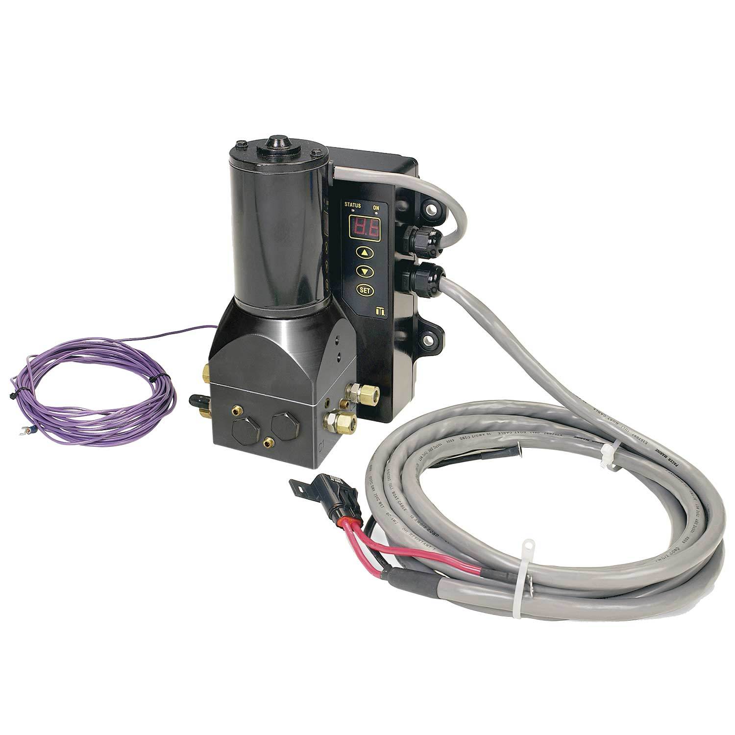
FIG. 1 shows that the preferred hydraulic winch assembly (winch assembly) 1 provides a fluid flow system, fluid cooling means and a control system for utilization of an existing vehicle hydraulic power steering pump 82 while assuring both efficient, reliable and independent steering system and winch operation. The fluid flow system comprises a conventional steering check valve 21 and winch check valve 31, a first and second electrically switchable multi-port diverter valves 32 and 42 respectively, a shutoff valve 33, tubing 45 and 46, interconnected with conventional fittings as will be described below. An in-line fluid cooler 5 cools hydraulic fluid during winch operation. A control system comprises a cabin-mounted control panel 6, an existing vehicle battery 86, and conventional wiring to the valves 32, 33 and 42.
FIG. 2 shows how, with the first diverter valve 42 in its default state, the winch is invisible to normal vehicle hydraulic steering operation. On demand, pressurized hydraulic fluid from the power steering pump 82 is directed by the first diverter valve 42 to a power steering box 81. Low pressure hydraulic fluid exiting the power steering box 81 passes through a unidirectional steering check valve 21 to the power steering pump 82 input. The winch check valve 31, located beyond a conventional "T"-shaped connector 44 prevents fluid from escaping the steering system.
FIGS. 3a through 3c show how, with the first diverter valve 42 in a switching state, the steering system is invisible to winch operations. Pressurized power steering fluid is pumped through the first diverter valve 42 and is directed toward the first diverter valve 32. The first diverter valve 32 is of the type having four ports inter-switchable amongst each other. As shown in FIG. 3a in a first switching state, pressurized hydraulic fluid is directed into an inlet port and thereby drives a hydraulic motor 71 in a forward direction, thereby releasing cable from a cable spool 72 coupled to the hydraulic motor 71. The pressurized fluid which exists from the hydraulic motor is then diverted back out into the fluid flow system toward the fluid cooling means.
As shown in FIG. 3b, the first diverter valve 32 is shown in a second state, wherein the pressurized hydraulic fluid is directed into the outlet port of the hydraulic motor 71, and then the hydraulic motor 71 is driven such that cable is rewound onto the cable spool 72. In this state the pressurized fluid exits out from the motor inlet and is directed back into the fluid flow system.
While in a third state as shown in FIG. 3c, hydraulic fluid bypasses the hydraulic motor 71 entirely, thereby providing for free spooling of the cable spool 72. While in the free-spooling state, an open biased, electrically switchable shutoff valve 33 affixed to the hydraulic motor 71 input can be switched to block fluid flow and thus provide free spool braking. This electrically switchable shutoff valve 33 can also be affixed to the hydraulic motor 71 output with equal performance.
In all of the three diverter states of the first diverter valve 32, fluid exiting or bypassing the hydraulic motor 71 passes through the fluid cooler 5, and then through the winch check valve 31 to return to the power steering pump 82. The steering check valve 21 prevents fluid from escaping toward the power steering box 81 output.
FIG. 4 shows how the fluid cooler 5 is a conventional convection cooled section of a tubing 51 with a larger metallic casing 52 to establish a larger, more efficient heat-exchanging surface area. The fluid cooler 5 is affixed in front of a conventional vehicle radiator 84 such that an existing fan 85 provides a draft for improved cooling.
Conventional interconnecting hoses are utilized throughout and connected in a manner consistent with a conventional hydraulic power steering system. Conventional high pressure tubing provides sufficient durability for highly pressurized fluid while low pressure fluid is accommodated by a conventional rubber hose. Conventional hose clamp clamping means are also utilized. Note, however, the lengths and diameters of the tubing and interconnects are exaggerated, for illustrative purposes, to more clearly show operational characteristics.
FIG. 5 shows the electrically controlled switching system for the valves 32, 33 and 42. Momentary switches are envisioned as an economical and simple means of providing safety and protection for the winch user. A winch button 61 must be depressed in order to switch and maintain the first diverter valve 42 in a position such that pressurized hydraulic fluid is re-directed for winch operation. Specific winch functions are further determined by the position of a three state function switch 62 which actuates the first diverter valve 32 into the various states as described above. Further, a momentary brake button 63 similarly opens the first diverter valve 32 to its third "free spooling" state and closes the shutoff valve 33 and for braking purposes. Thus the default path of fluid is that in which fluid is supplied for steering purposes. Accidental winch or free-spool operation is unlikely due to the need to retain the winch button 61 or brake button 63 in a depressed position.
The control panel 6 is releasingly mounted inside the vehicle cabin, thereby removing the operator from the zone danger proximate to the cable spool. However, the control panel 6 can also be removed for specialized applications.
The hydraulic motor 71 is coupled directly to the cable spool mount 72a. A keyed shaft 71a is then extended into a cable spool hub 72b. The outer ends of the hydraulic motor 71 and the cable spool 72 are then supported by bearings affixed to a conventional, heavy-duty winch bumper.
While the above description contains many specificities, these should not be construed as limitations on the scope of the invention, but rather as an example of the preferred embodiment thereof. Many other variations are possible within the spirit and scope of the present invention.
For example, the control panel utilizes electromechanical switching and hard wiring to minimize cost and for simplification. Computer control is anticipated for specialized applications such as weighing, event sequencing, additional safety, single stroke complex switching, etc. Such modification has become somewhat routine with the advent of inexpensive digital-to-analog and digital-to-analog conversion for control and monitoring respectively. Similarly, the control panel is easily made wireless by replacing the wiring with conventional matched transmitter and receiver modules. Both modifications further require either a signal conditioner for connection to the existing vehicle battery, a separate "winch battery", individual power supplies for each powered module or some combination.
Similarly, utilization of a momentary switch protection means is simply seen as the most economical means. Clearly other methods, such as disengagement of the controls while the vehicle is either in gear, while the tires are rotating, until microprocessor based protection feedback means are accommodated, until key combinations are depressed, etc. are anticipated. Other variations of the specific controls or control panel configuration are also anticipated.
Another example is that the fluid direction system and control means are clearly amenable to and provide an improvement to other hydraulic motor, spool and mounting configurations, such as the spool-enclosed motor of Johnson and its progeny. In addition, other known winch improvements, such as disc brakes of Gravenhurst, multiple-spooling as described in Bell, etc. and their progeny are anticipated. Once again, cost and simplicity are key considerations in establishing a preferred, but certainly not a singularly anticipated, embodiment.
Yet another example is that the multi-port valves and other connectors can alternatively be affixed, as is appropriate, directly to the power steering box, power steering pump and hydraulic motor in a conventional manner. The disadvantage of this approach is that installation becomes more difficult for typical retrofit applications. However, new components anticipating winch assembly incorporation will inevitably provide such integration. In addition, cost of such integration will certainly decrease as awareness and demand increase.
Another example is that a gear reduction box could be added between the hydraulic motor and the cable spool. The advantage of this approach would allow for a change of torque with the change in gear ratios.
Again, another example is that an electrically operated remote speed control device could be added to allow for increasing the combustion engine"s RPM above the idle range. When needed, this would help increase the output energy without the necessity of entering the driving compartment.

Hydraulic pumps are mechanisms in hydraulic systems that move hydraulic fluid from point to point initiating the production of hydraulic power. Hydraulic pumps are sometimes incorrectly referred to as “hydrolic” pumps.
They are an important device overall in the hydraulics field, a special kind of power transmission which controls the energy which moving fluids transmit while under pressure and change into mechanical energy. Other kinds of pumps utilized to transmit hydraulic fluids could also be referred to as hydraulic pumps. There is a wide range of contexts in which hydraulic systems are applied, hence they are very important in many commercial, industrial, and consumer utilities.
“Power transmission” alludes to the complete procedure of technologically changing energy into a beneficial form for practical applications. Mechanical power, electrical power, and fluid power are the three major branches that make up the power transmission field. Fluid power covers the usage of moving gas and moving fluids for the transmission of power. Hydraulics are then considered as a sub category of fluid power that focuses on fluid use in opposition to gas use. The other fluid power field is known as pneumatics and it’s focused on the storage and release of energy with compressed gas.
"Pascal"s Law" applies to confined liquids. Thus, in order for liquids to act hydraulically, they must be contained within a system. A hydraulic power pack or hydraulic power unit is a confined mechanical system that utilizes liquid hydraulically. Despite the fact that specific operating systems vary, all hydraulic power units share the same basic components. A reservoir, valves, a piping/tubing system, a pump, and actuators are examples of these components. Similarly, despite their versatility and adaptability, these mechanisms work together in related operating processes at the heart of all hydraulic power packs.
The hydraulic reservoir"s function is to hold a volume of liquid, transfer heat from the system, permit solid pollutants to settle, and aid in releasing moisture and air from the liquid.
Mechanical energy is changed to hydraulic energy by the hydraulic pump. This is accomplished through the movement of liquid, which serves as the transmission medium. All hydraulic pumps operate on the same basic principle of dispensing fluid volume against a resistive load or pressure.
Hydraulic valves are utilized to start, stop, and direct liquid flow in a system. Hydraulic valves are made of spools or poppets and can be actuated hydraulically, pneumatically, manually, electrically, or mechanically.
The end result of Pascal"s law is hydraulic actuators. This is the point at which hydraulic energy is transformed back to mechanical energy. This can be accomplished by using a hydraulic cylinder to transform hydraulic energy into linear movement and work or a hydraulic motor to transform hydraulic energy into rotational motion and work. Hydraulic motors and hydraulic cylinders, like hydraulic pumps, have various subtypes, each meant for specific design use.
The essence of hydraulics can be found in a fundamental physical fact: fluids are incompressible. (As a result, fluids more closely resemble solids than compressible gasses) The incompressible essence of fluid allows it to transfer force and speed very efficiently. This fact is summed up by a variant of "Pascal"s Principle," which states that virtually all pressure enforced on any part of a fluid is transferred to every other part of the fluid. This scientific principle states, in other words, that pressure applied to a fluid transmits equally in all directions.
Furthermore, the force transferred through a fluid has the ability to multiply as it moves. In a slightly more abstract sense, because fluids are incompressible, pressurized fluids should keep a consistent pressure just as they move. Pressure is defined mathematically as a force acting per particular area unit (P = F/A). A simplified version of this equation shows that force is the product of area and pressure (F = P x A). Thus, by varying the size or area of various parts inside a hydraulic system, the force acting inside the pump can be adjusted accordingly (to either greater or lesser). The need for pressure to remain constant is what causes force and area to mirror each other (on the basis of either shrinking or growing). A hydraulic system with a piston five times larger than a second piston can demonstrate this force-area relationship. When a force (e.g., 50lbs) is exerted on the smaller piston, it is multiplied by five (e.g., 250 lbs) and transmitted to the larger piston via the hydraulic system.
Hydraulics is built on fluids’ chemical properties and the physical relationship between pressure, area, and force. Overall, hydraulic applications allow human operators to generate and exert immense mechanical force with little to no physical effort. Within hydraulic systems, both oil and water are used to transmit power. The use of oil, on the other hand, is far more common, owing in part to its extremely incompressible nature.
Pressure relief valves prevent excess pressure by regulating the actuators’ output and redirecting liquid back to the reservoir when necessary. Directional control valves are used to change the size and direction of hydraulic fluid flow.
While hydraulic power transmission is remarkably useful in a wide range of professional applications, relying solely on one type of power transmission is generally unwise. On the contrary, the most efficient strategy is to combine a wide range of power transmissions (pneumatic, hydraulic, mechanical, and electrical). As a result, hydraulic systems must be carefully embedded into an overall power transmission strategy for the specific commercial application. It is necessary to invest in locating trustworthy and skilled hydraulic manufacturers/suppliers who can aid in the development and implementation of an overall hydraulic strategy.
The intended use of a hydraulic pump must be considered when selecting a specific type. This is significant because some pumps may only perform one function, whereas others allow for greater flexibility.
The pump"s material composition must also be considered in the application context. The cylinders, pistons, and gears are frequently made of long-lasting materials like aluminum, stainless steel, or steel that can withstand the continuous wear of repeated pumping. The materials must be able to withstand not only the process but also the hydraulic fluids. Composite fluids frequently contain oils, polyalkylene glycols, esters, butanol, and corrosion inhibitors (though water is used in some instances). The operating temperature, flash point, and viscosity of these fluids differ.
In addition to material, manufacturers must compare hydraulic pump operating specifications to make sure that intended utilization does not exceed pump abilities. The many variables in hydraulic pump functionality include maximum operating pressure, continuous operating pressure, horsepower, operating speed, power source, pump weight, and maximum fluid flow. Standard measurements like length, rod extension, and diameter should be compared as well. Because hydraulic pumps are used in lifts, cranes, motors, and other heavy machinery, they must meet strict operating specifications.
It is critical to recall that the overall power generated by any hydraulic drive system is influenced by various inefficiencies that must be considered in order to get the most out of the system. The presence of air bubbles within a hydraulic drive, for example, is known for changing the direction of the energy flow inside the system (since energy is wasted on the way to the actuators on bubble compression). Using a hydraulic drive system requires identifying shortfalls and selecting the best parts to mitigate their effects. A hydraulic pump is the "generator" side of a hydraulic system that initiates the hydraulic procedure (as opposed to the "actuator" side that completes the hydraulic procedure). Regardless of disparities, all hydraulic pumps are responsible for displacing liquid volume and transporting it to the actuator(s) from the reservoir via the tubing system. Some form of internal combustion system typically powers pumps.
While the operation of hydraulic pumps is normally the same, these mechanisms can be split into basic categories. There are two types of hydraulic pumps to consider: gear pumps and piston pumps. Radial and axial piston pumps are types of piston pumps. Axial pumps produce linear motion, whereas radial pumps can produce rotary motion. The gear pump category is further subdivided into external gear pumps and internal gear pumps.
Each type of hydraulic pump, regardless of piston or gear, is either double-action or single-action. Single-action pumps can only pull, push, or lift in one direction, while double-action pumps can pull, push, or lift in multiple directions.
Vane pumps are positive displacement pumps that maintain a constant flow rate under varying pressures. It is a pump that self-primes. It is referred to as a "vane pump" because the effect of the vane pressurizes the liquid.
This pump has a variable number of vanes mounted onto a rotor that rotates within the cavity. These vanes may be variable in length and tensioned to maintain contact with the wall while the pump draws power. The pump also features a pressure relief valve, which prevents pressure rise inside the pump from damaging it.
Internal gear pumps and external gear pumps are the two main types of hydraulic gear pumps. Pumps with external gears have two spur gears, the spurs of which are all externally arranged. Internal gear pumps also feature two spur gears, and the spurs of both gears are internally arranged, with one gear spinning around inside the other.
Both types of gear pumps deliver a consistent amount of liquid with each spinning of the gears. Hydraulic gear pumps are popular due to their versatility, effectiveness, and fairly simple design. Furthermore, because they are obtainable in a variety of configurations, they can be used in a wide range of consumer, industrial, and commercial product contexts.
Hydraulic ram pumps are cyclic machines that use water power, also referred to as hydropower, to transport water to a higher level than its original source. This hydraulic pump type is powered solely by the momentum of moving or falling water.
Ram pumps are a common type of hydraulic pump, especially among other types of hydraulic water pumps. Hydraulic ram pumps are utilized to move the water in the waste management, agricultural, sewage, plumbing, manufacturing, and engineering industries, though only about ten percent of the water utilized to run the pump gets to the planned end point.
Despite this disadvantage, using hydropower instead of an external energy source to power this kind of pump makes it a prominent choice in developing countries where the availability of the fuel and electricity required to energize motorized pumps is limited. The use of hydropower also reduces energy consumption for industrial factories and plants significantly. Having only two moving parts is another advantage of the hydraulic ram, making installation fairly simple in areas with free falling or flowing water. The water amount and the rate at which it falls have an important effect on the pump"s success. It is critical to keep this in mind when choosing a location for a pump and a water source. Length, size, diameter, minimum and maximum flow rates, and speed of operation are all important factors to consider.
Hydraulic water pumps are machines that move water from one location to another. Because water pumps are used in so many different applications, there are numerous hydraulic water pump variations.
Water pumps are useful in a variety of situations. Hydraulic pumps can be used to direct water where it is needed in industry, where water is often an ingredient in an industrial process or product. Water pumps are essential in supplying water to people in homes, particularly in rural residences that are not linked to a large sewage circuit. Water pumps are required in commercial settings to transport water to the upper floors of high rise buildings. Hydraulic water pumps in all of these situations could be powered by fuel, electricity, or even by hand, as is the situation with hydraulic hand pumps.
Water pumps in developed economies are typically automated and powered by electricity. Alternative pumping tools are frequently used in developing economies where dependable and cost effective sources of electricity and fuel are scarce. Hydraulic ram pumps, for example, can deliver water to remote locations without the use of electricity or fuel. These pumps rely solely on a moving stream of water’s force and a properly configured number of valves, tubes, and compression chambers.
Electric hydraulic pumps are hydraulic liquid transmission machines that use electricity to operate. They are frequently used to transfer hydraulic liquid from a reservoir to an actuator, like a hydraulic cylinder. These actuation mechanisms are an essential component of a wide range of hydraulic machinery.
There are several different types of hydraulic pumps, but the defining feature of each type is the use of pressurized fluids to accomplish a job. The natural characteristics of water, for example, are harnessed in the particular instance of hydraulic water pumps to transport water from one location to another. Hydraulic gear pumps and hydraulic piston pumps work in the same way to help actuate the motion of a piston in a mechanical system.
Despite the fact that there are numerous varieties of each of these pump mechanisms, all of them are powered by electricity. In such instances, an electric current flows through the motor, which turns impellers or other devices inside the pump system to create pressure differences; these differential pressure levels enable fluids to flow through the pump. Pump systems of this type can be utilized to direct hydraulic liquid to industrial machines such as commercial equipment like elevators or excavators.
Hydraulic hand pumps are fluid transmission machines that utilize the mechanical force generated by a manually operated actuator. A manually operated actuator could be a lever, a toggle, a handle, or any of a variety of other parts. Hydraulic hand pumps are utilized for hydraulic fluid distribution, water pumping, and various other applications.
Hydraulic hand pumps may be utilized for a variety of tasks, including hydraulic liquid direction to circuits in helicopters and other aircraft, instrument calibration, and piston actuation in hydraulic cylinders. Hydraulic hand pumps of this type use manual power to put hydraulic fluids under pressure. They can be utilized to test the pressure in a variety of devices such as hoses, pipes, valves, sprinklers, and heat exchangers systems. Hand pumps are extraordinarily simple to use.
Each hydraulic hand pump has a lever or other actuation handle linked to the pump that, when pulled and pushed, causes the hydraulic liquid in the pump"s system to be depressurized or pressurized. This action, in the instance of a hydraulic machine, provides power to the devices to which the pump is attached. The actuation of a water pump causes the liquid to be pulled from its source and transferred to another location. Hydraulic hand pumps will remain relevant as long as hydraulics are used in the commerce industry, owing to their simplicity and easy usage.
12V hydraulic pumps are hydraulic power devices that operate on 12 volts DC supplied by a battery or motor. These are specially designed processes that, like all hydraulic pumps, are applied in commercial, industrial, and consumer places to convert kinetic energy into beneficial mechanical energy through pressurized viscous liquids. This converted energy is put to use in a variety of industries.
Hydraulic pumps are commonly used to pull, push, and lift heavy loads in motorized and vehicle machines. Hydraulic water pumps may also be powered by 12V batteries and are used to move water out of or into the desired location. These electric hydraulic pumps are common since they run on small batteries, allowing for ease of portability. Such portability is sometimes required in waste removal systems and vehiclies. In addition to portable and compact models, options include variable amp hour productions, rechargeable battery pumps, and variable weights.
While non rechargeable alkaline 12V hydraulic pumps are used, rechargeable ones are much more common because they enable a continuous flow. More considerations include minimum discharge flow, maximum discharge pressure, discharge size, and inlet size. As 12V batteries are able to pump up to 150 feet from the ground, it is imperative to choose the right pump for a given use.
Air hydraulic pumps are hydraulic power devices that use compressed air to stimulate a pump mechanism, generating useful energy from a pressurized liquid. These devices are also known as pneumatic hydraulic pumps and are applied in a variety of industries to assist in the lifting of heavy loads and transportation of materials with minimal initial force.
Air pumps, like all hydraulic pumps, begin with the same components. The hydraulic liquids, which are typically oil or water-based composites, require the use of a reservoir. The fluid is moved from the storage tank to the hydraulic cylinder via hoses or tubes connected to this reservoir. The hydraulic cylinder houses a piston system and two valves. A hydraulic fluid intake valve allows hydraulic liquid to enter and then traps it by closing. The discharge valve is the point at which the high pressure fluid stream is released. Air hydraulic pumps have a linked air cylinder in addition to the hydraulic cylinder enclosing one end of the piston.
The protruding end of the piston is acted upon by a compressed air compressor or air in the cylinder. When the air cylinder is empty, a spring system in the hydraulic cylinder pushes the piston out. This makes a vacuum, which sucks fluid from the reservoir into the hydraulic cylinder. When the air compressor is under pressure, it engages the piston and pushes it deeper into the hydraulic cylinder and compresses the liquids. This pumping action is repeated until the hydraulic cylinder pressure is high enough to forcibly push fluid out through the discharge check valve. In some instances, this is connected to a nozzle and hoses, with the important part being the pressurized stream. Other uses apply the energy of this stream to pull, lift, and push heavy loads.
Hydraulic piston pumps transfer hydraulic liquids through a cylinder using plunger-like equipment to successfully raise the pressure for a machine, enabling it to pull, lift, and push heavy loads. This type of hydraulic pump is the power source for heavy-duty machines like excavators, backhoes, loaders, diggers, and cranes. Piston pumps are used in a variety of industries, including automotive, aeronautics, power generation, military, marine, and manufacturing, to mention a few.
Hydraulic piston pumps are common due to their capability to enhance energy usage productivity. A hydraulic hand pump energized by a hand or foot pedal can convert a force of 4.5 pounds into a load-moving force of 100 pounds. Electric hydraulic pumps can attain pressure reaching 4,000 PSI. Because capacities vary so much, the desired usage pump must be carefully considered. Several other factors must also be considered. Standard and custom configurations of operating speeds, task-specific power sources, pump weights, and maximum fluid flows are widely available. Measurements such as rod extension length, diameter, width, and height should also be considered, particularly when a hydraulic piston pump is to be installed in place of a current hydraulic piston pump.
Hydraulic clutch pumps are mechanisms that include a clutch assembly and a pump that enables the user to apply the necessary pressure to disengage or engage the clutch mechanism. Hydraulic clutches are crafted to either link two shafts and lock them together to rotate at the same speed or detach the shafts and allow them to rotate at different speeds as needed to decelerate or shift gears.
Hydraulic pumps change hydraulic energy to mechanical energy. Hydraulic pumps are particularly designed machines utilized in commercial, industrial, and residential areas to generate useful energy from different viscous liquids pressurization. Hydraulic pumps are exceptionally simple yet effective machines for moving fluids. "Hydraulic" is actually often misspelled as "Hydralic". Hydraulic pumps depend on the energy provided by hydraulic cylinders to power different machines and mechanisms.
There are several different types of hydraulic pumps, and all hydraulic pumps can be split into two primary categories. The first category includes hydraulic pumps that function without the assistance of auxiliary power sources such as electric motors and gas. These hydraulic pump types can use the kinetic energy of a fluid to transfer it from one location to another. These pumps are commonly called ram pumps. Hydraulic hand pumps are never regarded as ram pumps, despite the fact that their operating principles are similar.
The construction, excavation, automotive manufacturing, agriculture, manufacturing, and defense contracting industries are just a few examples of operations that apply hydraulics power in normal, daily procedures. Since hydraulics usage is so prevalent, hydraulic pumps are unsurprisingly used in a wide range of machines and industries. Pumps serve the same basic function in all contexts where hydraulic machinery is used: they transport hydraulic fluid from one location to another in order to generate hydraulic energy and pressure (together with the actuators).
Elevators, automotive brakes, automotive lifts, cranes, airplane flaps, shock absorbers, log splitters, motorboat steering systems, garage jacks and other products use hydraulic pumps. The most common application of hydraulic pumps in construction sites is in big hydraulic machines and different types of "off-highway" equipment such as excavators, dumpers, diggers, and so on. Hydraulic systems are used in other settings, such as offshore work areas and factories, to power heavy machinery, cut and bend material, move heavy equipment, and so on.
Fluid’s incompressible nature in hydraulic systems allows an operator to make and apply mechanical power in an effective and efficient way. Practically all force created in a hydraulic system is applied to the intended target.
Because of the relationship between area, pressure, and force (F = P x A), modifying the force of a hydraulic system is as simple as changing the size of its components.
Hydraulic systems can transfer energy on an equal level with many mechanical and electrical systems while being significantly simpler in general. A hydraulic system, for example, can easily generate linear motion. On the contrary, most electrical and mechanical power systems need an intermediate mechanical step to convert rotational motion to linear motion.
Hydraulic systems are typically smaller than their mechanical and electrical counterparts while producing equivalents amounts of power, providing the benefit of saving physical space.
Hydraulic systems can be used in a wide range of physical settings due to their basic design (a pump attached to actuators via some kind of piping system). Hydraulic systems could also be utilized in environments where electrical systems would be impractical (for example underwater).
By removing electrical safety hazards, using hydraulic systems instead of electrical power transmission improves relative safety (for example explosions, electric shock).
The amount of power that hydraulic pumps can generate is a significant, distinct advantage. In certain cases, a hydraulic pump could generate ten times the power of an electrical counterpart. Some hydraulic pumps (for example, piston pumps) cost more than the ordinary hydraulic component. These drawbacks, however, can be mitigated by the pump"s power and efficiency. Despite their relatively high cost, piston pumps are treasured for their strength and capability to transmit very viscous fluids.
Handling hydraulic liquids is messy, and repairing leaks in a hydraulic pump can be difficult. Hydraulic liquid that leaks in hot areas may catch fire. Hydraulic lines that burst may cause serious injuries. Hydraulic liquids are corrosive as well, though some are less so than others. Hydraulic systems need frequent and intense maintenance. Parts with a high factor of precision are frequently required in systems. If the power is very high and the pipeline cannot handle the power transferred by the liquid, the high pressure received by the liquid may also cause work accidents.
Even though hydraulic systems are less complex than electrical or mechanical systems, they are still complex systems that should be handled with caution. Avoiding physical contact with hydraulic systems is an essential safety precaution when engaging with them. Even when a hydraulic machine is not in use, active liquid pressure within the system can be a hazard.
Inadequate pumps can cause mechanical failure in the place of work that can have serious and costly consequences. Although pump failure has historically been unpredictable, new diagnostic technology continues to improve on detecting methods that previously relied solely on vibration signals. Measuring discharge pressures enables manufacturers to forecast pump wear more accurately. Discharge sensors are simple to integrate into existing systems, increasing the hydraulic pump"s safety and versatility.
Hydraulic pumps are devices in hydraulic systems that move hydraulic fluid from point to point, initiating hydraulic power production. They are an important device overall in the hydraulics field, a special kind of power transmission that controls the energy which moving fluids transmit while under pressure and change into mechanical energy. Hydraulic pumps are divided into two categories namely gear pumps and piston pumps. Radial and axial piston pumps are types of piston pumps. Axial pumps produce linear motion, whereas radial pumps can produce rotary motion. The construction, excavation, automotive manufacturing, agriculture, manufacturing, and defense contracting industries are just a few examples of operations that apply hydraulics power in normal, daily procedures.
Hydraulic Pumps are any of a class of positive displacement machines used in fluid power applications to provide hydraulic flow to fluid-powered devices such as cylinders, rams, motors, etc. A car’s power-steering pump is one example where an engine-driven rotary-vane pump is common. The engine’s gear-type oil pump is another everyday example. Hydraulic pumps can be motor-driven, too, or manually operated. Variable displacement pumps are especially useful because they can provide infinite adjustment over their speed range with a constant input rpm.
Pumps produce flow. Pressure is resistance to flow. Whereas centrifugal pumps can run against blocked discharges without building up excess pressure, positive-displacement pumps cannot. Hydraulic pumps, like any positive-displacement pump, thus require overpressure protection generally in the form of a pressure-relief valve. Over-pressure relief is often built into the pump itself.
Hydraulic systems are used where compact power is needed and where electrical, mechanical, or pneumatic systems would become too large, too dangerous, or otherwise not up to the task. For construction equipment, hydraulic power provides the means to move heavy booms and buckets. In manufacturing, hydraulic power is used for presses and other high-force applications. At the heart of the hydraulic system is the pump itself and the selection of a correct hydraulic pump hinges on just what the hydraulic system will be expected to do.
Axial piston pumps use axially mounted pistons that reciprocate within internal cylinders to create alternating suction and discharge flow. They can be designed as variable-rate devices making them useful for controlling the speeds of hydraulic motors and cylinders. In this design, a swashplate is used to vary the depth to which each piston extends into its cylinder as the pump rotates, affecting the volume of discharge. A pressure compensator piston is used in some designs to maintain a constant discharge pressure under varying loads.
Radial piston pumps arrange a series of pistons radially around a rotor hub. The rotor, mounted eccentrically in the pump housing, forces the pistons in and out of cylinders as it rotates, which cause hydraulic fluid to be sucked into the cylinder cavity and then be discharged from it. Inlets and outlets for the pump are located in a valve in a central hub. An alternative design places inlets and outlets around the perimeter of the pump housing. Radial piston pumps can be purchased as fixed- or variable-displacement models. In the variable-displacement version, the eccentricity of the rotor in the pump housing is altered to decrease or increase the stroke of the pistons.
Rotary vane pumps use a series of rigid vanes, mounted in an eccentric rotor, which sweep along the inside wall of a housing cavity to create smaller volumes, which forces the fluid out through the discharge port. In some designs, the volume of the fluid leaving the pump can be adjusted by changing the rotational axis of the rotor with respect to the pump housing. Zero flow occurs when the rotor and housing axes coincide.
External Gear pumps rely on the counter-rotating motion of meshed external spur gears to impart motion to a fluid. They are generally fixed-displacement designs, very simple and robust. They are commonly found as close-coupled designs where the motor and pump share a common shaft and mounting. Oil travels around the periphery of the pump housing between the teeth of the gears. On the outlet side, the meshing action of the teeth decreases the volume to discharge the oil. The small amount of oil that is trapped between the re-meshing gears discharges through the bearings and back to the pump’s suction side. External gear pumps are very popular in fixed-displacement hydraulic applications as they are capable of providing very high pressures.
The internal gear pump uses the meshing action of an internal and external gear combined with a crescent-shaped sector element to create fluid flow. The axis of the external gear is offset from that of the internal gear, and as the two gears rotate, their coming out of and into mesh create suction and discharge zones. The sector serves as a barrier between suction and discharge. Another internal gear pump, the gerotor, uses meshing trochoidal gears to achieve the same suction and discharge zones without needing a sector element.
This article presented a brief summary of some of the common types of hydraulic pumps. For more information on additional topics, consult our other guides or visit the Thomas Supplier Discovery Platform to locate potential sources of supply or view details on specific products.

This invention relates in general to hydraulic power steering pumps of the balanced vane type for use in automotive or mobile equipment applications, and in particular to hydraulic, power steering pumps having balanced low-pressure porting and a pressure plate.
Conventional balanced vane hydraulic pumps used in power steering applications have a generally cylindrical steel rotor with multiple vanes rotating within an oval path that is machined into a powdered iron cam ring. This mechanical arrangement is shown in simplified form in FIG. 1, where the rotor 20 has ten vanes 21-30 which rotate under power provided through a splined drive shaft 31. The outer edges of the vanes 21-30 are generally beveled or otherwise sharpened to a straight edge, and follow the generally elliptical machined inner surface 32 of cam ring 34 which is held in place relative to the pump housing (not shown in FIG. 1) by locator pins 36 and 38. The outer shape 40 of cam ring 34 is normally cylindrical. The high pressure outlet ports or "windows" 42 and 44 are shown in dashed lines at the top and bottom of the cam ring diametrically opposite to one another. The direction of pressure outlet ports or "windows" 42 and 44 are shown in dashed lines at the top and bottom of the cam ring diametrically opposite to one another. The direction of rotor rotation is Clockwise as indicated by arrow 45 in FIG. 1. The inlet ports or windows 46 and 48 are shown in dashed and solid lines and are diametrically opposite to one another, on the left side and right side respectively of cam ring 34.
In a conventional balanced vane pump, each vane is pressed outwardly against the inner surface 32 of the cam ring 34 by centrifugal force, and slides in and out within its own radially-aligned slot in rotor 20, as it spins around the cam ring. Hydraulic assist is provided via high pressure hydraulic fluid ported to undervane holes 51-60 in the rotor, which are respectively associated with vanes 21-30, and are part of the undervane porting system, to help ensure that the vanes faithfully track the inner surface 32 of the cam ring 34.
FIG. 2 is a hydraulic diagram showing the fluid circuit coupling the two sets of diametrically-opposed ports or windows. Outlet ports 42 and 44 are respectively connected by conduits 62 and 64 to a common high pressure gallery 65. Inlet ports 46 and 48 are connected by conduits 66 and 68 to a common low pressure gallery 69. High pressure hydraulic fluid discharged from ports 42 and 44 flows as indicated by broad arrows 72 and 74 into one stream of fluid indicated by arrow 75 to a pressure relief and flow control valve (not shown in FIGS. 1 or 2) which is normally built into the pump housing. Low pressure fluid discharged from the relief valve or obtained from a hydraulic reservoir which is indicated by arrow 79, is divided into two flows indicated by arrow 76 and 78 and passed to the inlet ports 46 and 48.
The two discharge ports 42 and 44 are 180° apart, as are the two inlet ports 46 and 48. Thus, pressures radially applied against the generally circular outer edge 80 of rotor 20 cancel each other. In this manner, forces on the rotor are largely balanced in a radial direction. Since two sets of ports are used, balanced vane pumps indicated by arrows 82 and 84 have two discharge or pumping quadrants or sectors 82 and 84, which discharge oil into outlet ports 42 and 44 respectively, and have two inlet quadrants or sectors, indicated by arrows 86 and 88, which respectively draw in fluid through inlet ports 46 and 48.
The displacement of a balanced vane pump, that is, its volumetric output per revolution, is fixed and depends on the width of the cam ring (which is the same as the width of the rotor), and the throw of the cam ring. Balanced vane pumps provide large displacements in a relatively small size package, especially since this type of pump can be operated at high speeds. Vane pumps are popular because of their small s


 8613371530291