
primary mover hydraulic pump free sample

We provide a variety of high-quality single and double-acting 12V hydraulic pumps. Choose from a selection of poly or steel reservoir sizing options. Our pumps are ideal for application with Dump Trailers and more. Browse our shop today and find the right hydraulic pump for your hydraulic circuit needs!
As a hydraulic instructor and consultant, I have met thousands of people whose job consists, at least in part, of the maintenance and repair of hydraulic systems. The number of hydraulic troubleshooters I have come across, however, I can count on the fingers of one hand.
For the most part, I have encountered a lot of excellent hydraulic parts changers. These are people who have worked on and around hydraulic systems for so long that they know changing a specific part typically corrects a certain problem. They may or may not know exactly why this is, but they know from experience that replacing this part fixes the problem.
If I had to pick a single concept that keeps most parts changers from becoming troubleshooters, it would be the failure to understand the difference between pressure and flow. It is not uncommon to hear the terms used interchangeably, as though they are synonyms. They aren’t. I often hear the complaint that a pump isn’t putting out as much pressure as it should, implying that the pump is supposed to deliver pressure.
A common assumption is that if the pressure is low, the pump must be bad. This is not the case. The pump doesn’t pump pressure. The pump delivers a rate of flow. The single function of the pump is to take fluid from one place and put it somewhere else. Pressure is the result of resistance to flow. In our training classes, we use the simple schematic shown above to explain this concept.
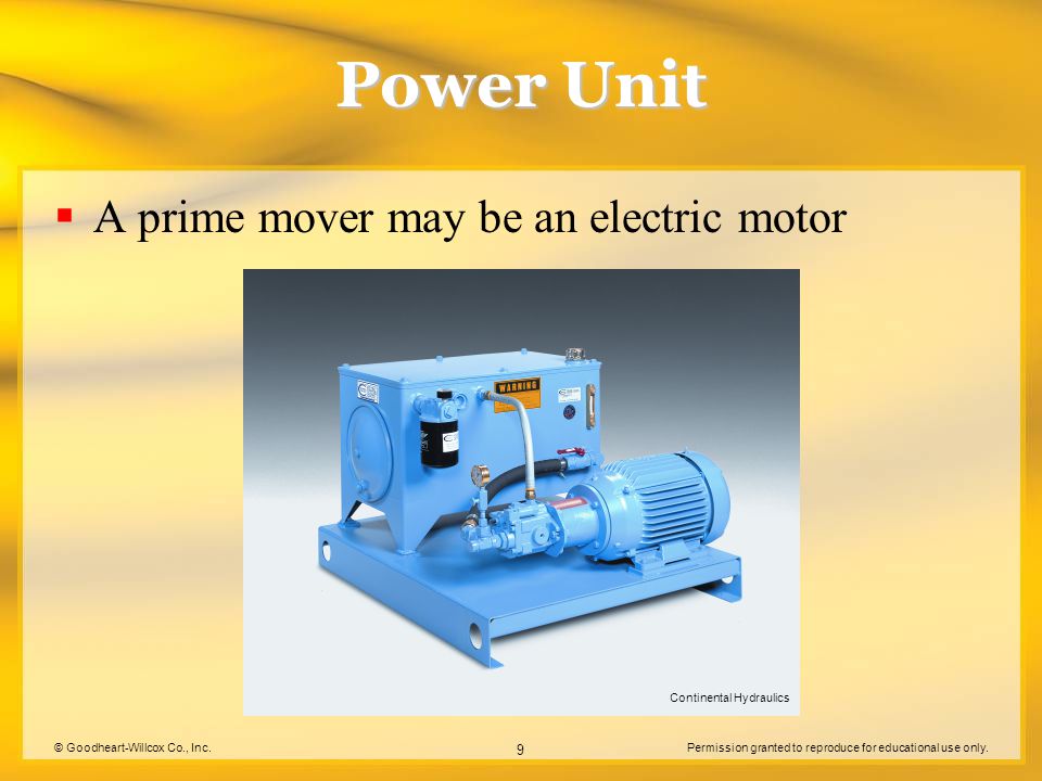
A fixed-displacement pump is the simplest type of hydraulic pump. It is turned by a primary mover, generally an electric drive motor or, in mobile equipment, the same engine that moves the machine. The amount of flow is determined by the displacement and speed of the drive motor. By “displacement,” I mean the amount of fluid delivered for each full rotation of the pump.
On typical industrial systems, the pump is turned at a constant speed and therefore delivers a constant amount of flow. When the pump is started, oil is moved from the reservoir and into the system. The higher the flow rate, the faster the actuator will move.
If you trace the flow from the pump, you reach a “T” in the line. Whenever you follow the flow on a schematic and arrive at a line split, you must track the flow in both directions to determine the path of least resistance. Hydraulic fluid always takes the path of least resistance. I
Also, note the dotted line. In hydraulic schematics, a dotted line usually represents a flow path that is somewhat smaller than that of a solid line, typically a drain line or a pilot line. The one shown in the schematics on the left is a pilot line connected immediately upstream of the valve. Whatever pressure is in the main line will be present in the pilot line.
The line terminates into an open drum. When the pump is turned on, as shown in the schematic on the left, the path of least resistance in this case is to the drum, not through the relief valve. The pressure reading on the gauge is 0 psi.
Clearly, the reason the gauge reads so low is because there is no resistance in the system. However, I have seen many pumps replaced for no other reason than because the pressure in the system was low. Over the years, I have received numerous phone calls that started out, “Well, I have changed the pump, but my pressure is still low. What else should I look for?”
In fact, a pressure problem in a hydraulic system is rarely the pump. It is almost always another bad component in the system. The pump should never be the first component to try but rather your last resort when a pressure problem exists. In the example shown, replacing the pump would deliver exactly the same result.
On many occasions, I have heard remarks such as, “My pump is putting out 1,500 psi.” This illustrates the misconception that pressure originates at the pump.
As you can see, what is being read on the gauge is not how much pressure the pump is putting out but rather the amount of resistance currently being overcome in the system. Without a firm understanding of this concept, becoming a troubleshooter is impossible.
Jack Weeks is a hydraulic instructor and consultant for GPM Hydraulic Consulting. Since 1997 he has trained thousands of electricians and mechanics in hydraulic troubleshooting methods. Jack has...

Hydraulic pumps are used in hydraulic drive systems and can be hydrostatic or hydrodynamic. A hydraulic pump is a mechanical source of power that converts mechanical power into hydraulic energy (hydrostatic energy i.e. flow, pressure). It generates flow with enough power to overcome pressure induced by the load at the pump outlet. When a hydraulic pump operates, it creates a vacuum at the pump inlet, which forces liquid from the reservoir into the inlet line to the pump and by mechanical action delivers this liquid to the pump outlet and forces it into the hydraulic system.
Hydrostatic pumps are positive displacement pumps while hydrodynamic pumps can be fixed displacement pumps, in which the displacement (flow through the pump per rotation of the pump) cannot be adjusted, or variable displacement pumps, which have a more complicated construction that allows the displacement to be adjusted. Hydrodynamic pumps are more frequent in day-to-day life. Hydrostatic pumps of various types all work on the principle of Pascal"s law.
Gear pumps (with external teeth) (fixed displacement) are simple and economical pumps. The swept volume or displacement of gear pumps for hydraulics will be between about 1 to 200 milliliters. They have the lowest volumetric efficiency (η
A rotary vane pump is a positive-displacement pump that consists of vanes mounted to a rotor that rotates inside a cavity. In some cases these vanes can have variable length and/or be tensioned to maintain contact with the walls as the pump rotates. A critical element in vane pump design is how the vanes are pushed into contact with the pump housing, and how the vane tips are machined at this very point. Several type of "lip" designs are used, and the main objective is to provide a tight seal between the inside of the housing and the vane, and at the same time to minimize wear and metal-to-metal contact. Forcing the vane out of the rotating centre and towards the pump housing is accomplished using spring-loaded vanes, or more traditionally, vanes loaded hydrodynamically (via the pressurized system fluid).
Screw pumps (fixed displacement) consist of two Archimedes" screws that intermesh and are enclosed within the same chamber. These pumps are used for high flows at relatively low pressure (max 100 bars (10,000 kPa)).ball valves
The major problem of screw pumps is that the hydraulic reaction force is transmitted in a direction that"s axially opposed to the direction of the flow.
Bent axis pumps, axial piston pumps and motors using the bent axis principle, fixed or adjustable displacement, exists in two different basic designs. The Thoma-principle (engineer Hans Thoma, Germany, patent 1935) with max 25 degrees angle and the Wahlmark-principle (Gunnar Axel Wahlmark, patent 1960) with spherical-shaped pistons in one piece with the piston rod, piston rings, and maximum 40 degrees between the driveshaft centerline and pistons (Volvo Hydraulics Co.). These have the best efficiency of all pumps. Although in general, the largest displacements are approximately one litre per revolution, if necessary a two-liter swept volume pump can be built. Often variable-displacement pumps are used so that the oil flow can be adjusted carefully. These pumps can in general work with a working pressure of up to 350–420 bars in continuous work.
By using different compensation techniques, the variable displacement type of these pumps can continuously alter fluid discharge per revolution and system pressure based on load requirements, maximum pressure cut-off settings, horsepower/ratio control, and even fully electro proportional systems, requiring no other input than electrical signals. This makes them potentially hugely power saving compared to other constant flow pumps in systems where prime mover/diesel/electric motor rotational speed is constant and required fluid flow is non-constant.
A radial piston pump is a form of hydraulic pump. The working pistons extend in a radial direction symmetrically around the drive shaft, in contrast to the axial piston pump.

Calculation of preliminary cooler capacity: Heat dissipation from hydraulic oil tanks, valves, pipes and hydraulic components is less than a few percent in standard mobile equipment and the cooler capacity must include some margins. Minimum cooler capacity, Ecooler = 0.25Ediesel
At least 25% of the input power must be dissipated by the cooler when peak power is utilized for long periods. In normal case however, the peak power is used for only short periods, thus the actual cooler capacity required might be considerably less. The oil volume in the hydraulic tank is also acting as a heat accumulator when peak power is used.
The system efficiency is very much dependent on the type of hydraulic work tool equipment, the hydraulic pumps and motors used and power input to the hydraulics may vary considerably. Each circuit must be evaluated and the load cycle estimated. New or modified systems must always be tested in practical work, covering all possible load cycles.

This application claims the benefit of a provisional U.S. patent application entitled HYDRAULIC PUMP WITH ELECTRIC GENERATOR, having a Ser. No. 62/174,242, filed Jun. 11, 2015. The disclosure of this application is hereby incorporated by reference in its entirety.
The present invention relates generally to hydraulic pumps. More particularly, the present invention relates to a hydraulic pump configured to use the rotating shaft of a prime mover configured to operate the pump to also generate electric power.
Hydraulic pumps are often operated at construction or other work sites that do not always have access to electric power. The hydraulic pumps may be operated by a variety of different prime movers. For example, gasoline motors, diesel motors, pneumatic motors, natural gas motors, propane powered motors or any other type of motor may be used to drive a hydraulic pump. In many instances, the prime mover may provide a rotating shaft to the hydraulic pump. The hydraulic pump then has a shaft that connects to the output shaft of the prime mover in order to operate the hydraulic pump.
In some instances, it may be useful to have some electric power available in addition to the mechanical shaft power provided by the prime mover. For example, certain hydraulic valves may be electrically operated or controlled by electronic controller that runs on electricity. In other instances various valves a be moved by electric actuators. In still other instances, other devices may run on electricity forming a desire for electric power to be generated by the energy or rotating shaft of the prime mover. In some instances, generators may not be used to generate electric power because of arcing or sparks that may occur within the generator. For example, in mines where flammable gases may accumulate such generators should not be used. Accordingly, it is desirable to provide a method and apparatus that can use the rotating shaft provided by a prime mover to run both a hydraulic pump and generate electric power.
The foregoing needs are met, to a great extent, by the present invention, wherein in one aspect an apparatus is provided that in some embodiments uses a rotating shaft powered by a prime mover to run both a hydraulic pump and generate electricity.
In accordance with one embodiment of the present invention, a hydraulic pump is provided. The pump includes: a pump shaft adapter configured to rotate and operate the hydraulic pump thereby; a magneto operatively connected to the pump shaft adapter; conductors extending from the magneto connecting the magneto to a power outlet to provide electricity generated by the magneto to the power outlet; and a hydraulic pump housing enclosing both the hydraulic pump and the magneto.
In accordance with another embodiment of the present invention, a method of generating electricity is provided. The method includes: adapting a pump shaft to include an attaching structure; attaching a magneto to the attaching structure; and configuring the magneto to generate electricity when the pump shaft rotates.
In accordance with yet another embodiment of the present invention, a hydraulic pump is provided. The pump may include: a means for transmitting mechanical power configured to rotate and operate the hydraulic pump thereby; a means for generating electrical power operatively connected to the means for transmitting mechanical power; means for transmitting electrical power extending from the means for generating electrical power to a power outlet to provide electricity generated by the means for generating electrical power to the power outlet; and a hydraulic pump housing enclosing both the hydraulic pump and the means for generating electrical power.
FIG. 2 is a front view of a motorized hydraulic pump with part of the housing removed in order to show internal components according to embodiments of the present disclosure.
FIG. 8 is a perspective, partial, enlarged cross-sectional view of a portion of the motorized hydraulic pump according to an embodiment of the disclosure.
The various embodiments in accordance with the present disclosure will now be described with reference to the drawing figures, in which like reference numerals refer to like parts throughout. An embodiment in accordance with the present disclosure provides a motorized hydraulic pump. The motorized hydraulic pump is driven by a prime mover. The prime mover provides energy to run the hydraulic pump in the form of a rotating shaft. In addition to performing pumping operations, the hydraulic pump is capable of generating electricity. Electricity may be used for a variety of purposes including operating hydraulic valves that may receive pressurized hydraulic fluid from the hydraulic pump.
FIGS. 1, 2, and 3 illustrate a motorized hydraulic pump 10 in accordance with the present disclosure. The motorized hydraulic pump 10 includes a prime mover 12. The prime mover 12 illustrated in FIGS. 1-3 includes a gasoline reciprocating engine. However, in other embodiments, a variety of prime movers 12 may be used. For example, the prime mover 12 may be a pneumatic motor, a hydraulic motor, an engine running on propane or natural gas or any other motor that is configured to rotate a shaft.
FIGS. 1-3 illustrate a power generation assembly 14. The power generation assembly 14 is located in between the prime mover 12 and the hydraulic pump 18. The power generation assembly 14 shown in FIG. 1 is covered by a housing 16. In some embodiments, the housing 16 is part of the hydraulic pump 18 such that the power generation assembly 14 is contained within the housing 16 of the hydraulic pump 18. The housing 16 is removed (or, at least, partially removed) in FIGS. 2 and 3 to better illustrate the parts of the power generation assembly 14.
FIG. 2 is an assembled view of the motorized hydraulic pump 10 with the housing 16 removed. FIG. 3 is a partially exploded view of the motorized hydraulic pump 10 where the prime mover 12 and the hydraulic pump 18 are intact but separated from each other. As shown in FIGS. 2 and 3, the prime mover 12 has a drive shaft 22 that extends down below the prime mover 12 toward the power generation assembly 14. The power generation assembly 14 may be a magneto 20. The magneto 20 may include a rotor 21 and a stator assembly 26 which will be discussed in further detail later below. The magneto 20 is attached to an adapted pump shaft 24 which is also connected to the drive shaft 22 of the prime mover 12. In some embodiments, it is the adapted pump shaft 24 which is attached to the power generation assembly 14 and also drives the hydraulic pump 18.
FIG. 4 is a perspective view of the adapted pump shaft 24. FIG. 5 is an end view of the adapted pump shaft 24 having a broken out portion 44 which allows better illustration of some of the aspects of the adapted pump shaft 24 described below. With respect to FIGS. 4 and 5, the adapted pump shaft 24 includes a shaft portion 28 terminated at one end with a flat end portion 30.
In some embodiments, the flat end portion 30 is configured to engage with components of the hydraulic pump 18 to drive the hydraulic pump 18 (See FIGS. 1-3 for the hydraulic pump 18). The adapted pump shaft 24 may have a larger diameter portion 32 which has a larger diameter than the shaft portion 28. The larger diameter portion 32 may include a set screw hole 34 which, in some embodiments, may be threaded. The screw hole 34 may be used to allow a screw to enter the screw hole 34 and urge against the shaft 22 to better keep it in place within the adapted pump shaft 24.
The adapted pump shaft 24 may be particularly adapted in order to both drive the hydraulic pump 18 and the rotor 21. In this regard, the adapted pump shaft 24 may include attaching structure such as, but not limited to, a flange 36 having connecting holes 38. The flange 36 and connecting holes 38 may allow the adapted pump shaft 24 to attach to the rotor 21 which will be described in additional detail below. The adapted pump shaft 24 may also define an opening 40. In some embodiments, the opening 40 may be encompassed about by a raised lip portion 41. Furthermore, in some embodiments, the opening 40 may also include a keyway 42 which may be dimensioned to engage with a key located on the drive shaft 22 in order to provide a positive rotational connection between the drive shaft 22 coming from the prime mover 12 and the adapted pump shaft 24.
FIG. 6 is a partial cross-sectional view of the motorized hydraulic pump 10. The drive shaft 22 is shown extending from the prime mover 12 through the rotor 21 and stator assembly 26 and connecting to the adapted pump shaft 24. The attaching bolts or fasteners 46 are shown extending through attaching holes 47 in the rotor 21 and the connecting holes 38 in the adapted pump shaft 24. In this manner, the flange 36 of the adapted pump shaft 24 is secured against the mounting surface 49 of the rotor 21.
The rotor 21 has a receiving hole 48. In some embodiments, the receiving hole 48 has been modified or formed so that it is dimensioned to permit the raised lip portion 41 of the adapted pump shaft 24 to extend into the rotor 21. In some embodiments, the receiving hole 48 is modified from a tapered shape common to off-the-shelf parts and is squared off as shown. The adapted pump shaft 24 sits upon a bearing 51 and extends into the hydraulic pump 18.

This invention generally relates to closed loop hydraulic power transmission systems or hydrostatic transmissions. In particular, it is concerned with a unique hydraulic circuit that prevents overspeeding of the prime mover by automatically insuring that the hydraulic pressure available to decelerate an inertial load is lower than that pressure which was available to accelerate the load.
(b) a hydraulic pump, normally a variable displacement pump, which is driven by the prime mover and which produces a flow of pressurized hydraulic fluid;
(e) mechanical shafting and gearing to convey the output of the hydraulic motor to the load. The hydraulic pump is normally driven at a constant speed by the prime mover; if it is a variable displacement pump, it delivers hydraulic fluid at a variable rate to the hydraulic motor. Thus, by controlling the output of the hydraulic pump, the direction and speed of the hydraulic motor, and hence direction and speed of the load can be controlled.
In many hydraulic drive systems or hydrostatic transmissions, a mass or load is accelerated and brought to speed by pumping fluid in one direction from the hydraulic pump to the hydraulic motor and decelerated or braked by attempting to reverse the flow of fluid from the hydraulic pump to the hydraulic motor (e.g. dynamic braking). This method of controlling the acceleration and deceleration of an inertial load is convenient, stable, well-proven and precise. If the reversing feature of the hydraulic pump is used in an ordinary hydrostatic drive, the same hydraulic pressure is normally used to both accelerate and decelerate the load.
In the case of an axial piston hydraulic pump the amount of flow and the direction of flow is determined by the angle of the tilt plate or swash plate. These axial piston pumps are often referred to as variable delivery or variable displacement hydraulic pumps. When the swash plate is at right angles to the drive shaft (i.e. zero tilt) and the drive shaft is rotating, the pistons which pump the fluid do not reciprocate; therefore, no pumping action takes place. When the swash plate is tilted from the right angle position, the pistons reciprocate and hydraulic fluid is pumped. The design and operation of axial piston hydraulic motors is very similar to the design and operation of an axial piston hydraulic pump. It well known that some hydraulic pumps can be used as hydraulic motors with little or no modification.
The output speed and torque of a hydraulic motor depend upon the power input in terms of differential pressure and the rate of flow. The relationship between output speed vs. input volume and output torque vs. input differential pressure depends on displacement of the motor. In particular, the output torque is proportional to the input differential pressure and the flow rate and inversely proportional to the speed (RPM). This follows from the fact that in a prime mover hydraulic pump system combination, the torque of the input shaft is proportional to the hydraulic pressure and the flow through the system. Therefore, if system pressure is limited, shaft torque or input torque will also be limited, for a given pump displacement.
Fluid motors may be of the fixed displacement or variable displacement type. The fixed displacement provides constant torque and variable speed for a given differential pressure. The speed is varied by controlling the amount of input flow. The variable displacement motor is constructed in a manner which permits the working relationship of the internal parts to be varied so as to change the displacement. This provides variable torque and variable speed. With input flow and operating pressure remaining constant, the relationship between the torque and the speed can be varied to meet load requirements by varying the displacement. The majority of motors used in fluid power systems are the fixed displacement types. In most fluid power systems, the motor is required to provide actuation in either direction. This is, of course, achieved by changing the angle of the swash plate in the variable displacement hydraulic pump.
Because of the similarity in the operation and construction of the hydraulic pump and hydraulic motor, particularly a variable displacement hydraulic pump of the axial piston variety and an axial piston hydraulic motor, a hydraulic motor acts as a hydraulic pump when the hydraulic pump has its displacement reduced (by decreasing the angle of the swash plate) to a volume less than the volume passing through the motor and the load connected to the output shaft of the hydraulic motor is in motion. Effectively, the inertia of the load drives the hydraulic motor in such a way that it "pumps" hydraulic fluid.
However, most prime movers do not have a retarding torque characteristic equal to their driving torque characteristic. In other words, the prime mover accelerates a load at a different rate than it decelerates a load. Consequently, if a load in motion is decelerated by the application of decelerating pressure, the magnitude of which is equal to the pressure previously used to accelerate that load, the hydraulic pump and the associated prime mover can overspeed. Overspeeding the hydraulic pump or the prime mover can cause damage or excessive wear to either or both of the components. Thus, if overspeeding is to be avoided, a lower pressure should be used to decelerate the moving load. Although the rate of deceleration is reduced by using a lower hydraulic pressure, operationally this is of no significance since most machines also have mechanical brakes to slow or stop the moving load. These mechanical brakes are normally used in conjunction with the retarding feature of the variable displacement hydraulic pump.
In accordance with the present invention a hydraulic circuit is provided to prevent overspeeding of the prime mover and hydraulic pump of a closed loop hydrostatic transmission when the flow through the hydraulic pump is retarded to brake or decelerate a moving load connected to the hydraulic motor driven by the hydraulic pump. In the case of a variable displacement hydraulic pump whose swash plate or tilt plate is positioned by a hydraulic servomechanism, the hydraulic fluid used to operate the servomechanism is shut off if the hydraulic pressure in either of the two main conduits (i.e. the ones passing hydraulic fluid between the hydraulic pump and hydraulic motor of a closed loop hydrostatic transmission) exceeds a pre-set maximum value, or if the auxiliary hydraulic pressure exceeds the pre-set maximum value, or if the hydraulic pressure in either of the two conduits and the auxiliary hydraulic pressure when added together exceeds that same pre-set maximum value.
Pressure compensation is introduced into the servomechanism by comparing the pre-set maximum pressure value against the pressure in either of the two main conduits. The auxiliary hydraulic pressure signal is equal to the lowest value of pressure during acceleration and the highest during deceleration of the load. Alternatively, it can be viewed as the pressure in that conduit which, for a given direction of rotation of the hydraulic motor, would be at the higher pressure if the hydraulic pump were not operating and the hydraulic motor was rotating due to the rotational inertia of the load.
The pre-set maximum pressure value is a pressure which varies with the angle of tilt on the swash plate and hence the displacement or flow of the hydraulic pump. In particular, the pre-set maximum pressure decreases in value as the angle of tilt on the swash plate increases in value. Because the pre-set maximum pressure value decreases as the angle of tilt on the swash plate increases, the maximum pressure allowable in either of the two conduits decreases with increasing flow from the hydraulic pump. This introduces horsepower (or torque) compensation into the servomechanism.
Thus, the servomechanism, when compensated for the pressure (or torque loading) on the hydrostatic transmission, cannot be operated to overspeed the prime mover or the hydraulic pump powered by the prime mover. Other specific advantages and features of the invention will become readily apparent from the following detailed description of the invention, from the embodiment illustrated therein, from the claims, and from the accompanying drawings.
The carrier also has an operator"s compartment or cab 30 supported at one corner of the bridge 14. There the equipment attendant or driver manipulates the various controls used to operate the carrier 10. The cab is accessible through a ladder 31 attached to one of the forward or front legs 16. An engine compartment 26 is supported by one of the two hollow beams 24 at the lower ends of the legs 16. The engine contained therein drives a plurality of pumps that supply hydraulic fluid to a plurality of motors and actuators to operate various moving components and equipment. In particular, a spreader 32 is supported by the bridge 14 for vertical movement within the open bay 28 through a hoisting mechanism. The spreader is used to manipulate cargo containers or vans 36. The wheels 18 are steered by a plurality of fluid rams 38 through a linkage so that all of the wheels are turned in a synchronized relationship. The wheels 18 are driven by hydraulic drive motors which are in turn powered by the hydraulic pumps and the engine 42 within the engine compartment 26 through a hydraulic transmission means 40 (see FIG. 2). Additional details concerning the straddle carrier 10 referred to in FIG. 1 may be found in U.S. Pat. No. 4,119,229 to Holmes et al. and assigned to the assignee of the present invention. That patent, insofar as providing additional details describing the various relationships between the components of the present invention is herein incorporated by reference.
The major components of the hydraulic circuit used to operate or power the wheels 18 of the straddle carrier 10 will now be described. The hydraulic transmission means 40 used to drive the wheels 18 can take on a variety of forms. FIG. 2 is a schematic diagram illustrating one type of drive incorporating a closed loop hydrostatic transmission. An engine 42 such as a diesel engine or gasoline engine drives a variable displacement hydraulic pump 44 through an input or drive shaft 45. That same shaft drives a charging pump 46. A pair of main conduits or fluid lines 47 and 48 supplies hydraulic fluid from the pump 44 to a hydraulic motor 50. For convenience, one of the two main conduits 47 will be alternatively referred to as the "upper main conduit" and the other main conduit 48 will be referred to as the "lower main conduit". The hydraulic pump 44 is of the reversible flow variety so that pressurized fluid may be delivered to either of the two main conduits 47 and 48 to control the direction of rotation of the hydraulic motor 50 and the wheels 18. A hydraulic servomechanism 64 is used to control the speed and direction of rotation of the hydraulic pump 44. The wheels 18 are joined to the hydraulic motor 50 by an output shaft 52.
The charging pump is used to supply control oil or fluid to operate or power the servomechanism 64. The charging pump 46 is connected to a hydraulic fluid reservoir or sump 54. The charging pump 46 is a constant displacement pump delivering a constant supply of fluid to a header 56 which is connected to the two main conduits 47 and 48 through check valves 57 and 58 and to a pressure relief valve 60. Thus, pressurized fluid from the charging pump 46 is automatically added to the closed loop hydrostatic transmission including the variable displacement, reversible flow hydraulic pump 44, the two main conduits 47 and 48, and the hydraulic motor 50 whenever such fluid is necessary. For example, if the upper main conduit 47 is pressurized, by the hydraulic pump 44, the pressure of the fluid therein will always be greater than the relief valve setting of the charging pump relief valve 60 so as to maintain the upper check valve 57 in the closed or seated position. If the closed loop hydrostatic transmission is in need of additional fluid, the pressure in the lower conduit 48 will drop below the setting of the charging pump relief valve 60. This in turn opens the lower check valve 58 so as to supply charging oil to the lower main conduit 48.
The hydraulic transmission means 40 also incorporates a high pressure relief system for interconnecting the upper 47 and lower 48 main conduits any time there is a sudden surge of pressure of the fluid in either conduit. This is accomplished by connecting the upper and lower main conduits 47 and 48 by a pair of relief valves 61 and 62. One relief valve 61 protects the upper main conduit 47 from a sudden surge in pressure. The second relief valve 62 protects the lower main conduit 48 from a sudden increase in pressure. With the relief circuit just described, whenever the hydraulic pump 44 is suddenly shut down for any reason, the momentum of the carrier 10 can result in a rapid rise in pressure in either the upper 47 or the lower 48 conduits, (depending on the direction of motion of the carrier) which in turn will open the appropriate relief valve 61, 62 to provide a flow path bypassing the hydraulic pump 44. Other details concerning the specific components of the hydraulic transmission means 40 may be found in Holmes et al. U.S. Pat. No. 4,119,229 previously referenced.
The servomechanism 64 used to operate, control and adjust the hydraulic pump 44 will now be described. The servomechanism 64 is of the hydromechanical variety. It includes a control valve 66; a positioner or servocylinder 68; an input lever 70; and a drive link 72. The drive link 72 is joined to the swash plate or tilt plate 74 of hydraulic pump 44. The positioner 68 manipulates the drive link 72 to control the angle 75 of the swash plate 74. Position feedback between the control valve 66 and the swash plate 74 is obtained by linking the drive link 72 to the input lever 70. The input lever 70 controls the position of a spool within the control valve 66 and the flow path of hydraulic fluid to and from the positioner 68.
As shown in the drawings, control valve 66 is a three-position, four-way valve biased to the center position. The two output ports 76 and 77 of the control valve 66 are fluidly connected to both sides of the piston 78 within the positioner or servocylinder 68. The control valve 66 has two input ports 79 and 81. A supply of "control oil" is fed to one of the input ports 79 of the control valve 66 via a conduit 80 joined to a header 56 downstream of the charging pump 46. A pressure limiting valve 82 (to be described in detail at a later point in this discussion) controls the supply of hydraulic fluid flowing from the charging pump 46 to the control valve 66. The other input conduit 81 directs fluid displaced by the movement of the piston 78 within the positioner 68 to the reservoir 54. Thus, by operating the input lever 70 the control valve 66 can be positioned to supply fluid to either side of the piston 78 in the positioner 68 so as to force the piston rod 83 inwardly or outwardly thereby controlling the angle 75 of the swash plate 74 in the hydraulic pump 44. By pivotally linking together the drive link 72 with the input lever 70, the displacement of the swash plate and the movement of the drive link 72 is "fed back" to the input lever. These principles are conventional and well-known to those skilled in the art. Thus, so long as hydraulic fluid under pressure is provided to the control valve 66, the driver or machinery operator of straddle carrier 10 is free to manipulate the swash plate 74 and thereby control the operation of the variable displacement hydraulic pump 44. However, if the supply of hydraulic fluid to the control valve 66 is shut off, the swash plate 74 cannot be operated by manipulating the input lever 70. This is the function of the pressure limiting valve 82 which will now be described in detail.
One valve pilot 84 is joined to a conduit 89 providing hydraulic fluid from a shuttle valve 90. The shuttle valve has its two input ports 91U and 91L joined to the two main conduits 47 and 48 of the hydraulic transmission means 40. The output from the shuttle valve 90 is a "pressure signal" (i.e. a source of pressurized fluid) that is equal in pressure to the higher of the pressures in the two main conduits 47 and 48. Thus, when the upper conduit 47 is higher in pressure than the lower main conduit 48, the shuttle valve 90 provides at its output port 91o fluid, the pressure of which is equal to the pressure of the hydraulic fluid in the upper main conduit 47. When the hydraulic pump 44 is running at a constant speed (RPM) and pumping fluid to the upper main conduit 47 and from the lower main conduit 48, the pressure of the fluid in the higher of the two main conduits is proportional to the torque loading on the hydraulic motor. Moreover, the torque on the input shaft 45 and the engine 42 is proportional to this same hydraulic pressure. Effectively, by using this pressure to control operation of the pressure limiting valve 82, pressure compensation is introduced. This pressure signal (e.g. pressure at the output port 91o of the shuttle valve 90) will be referred to as the "pressure compensating signal."
The second valve pilot 85 is supplied with hydraulic fluid under pressure from a conduit 92 joined to either the upper 47 or the lower 48 main conduits through a restriction orifice 93, 94 and an auxiliary pressure control valve 95. As illustrated in the drawings the auxiliary pressure control valve 95 is a two-position, four-way valve that is biased to one position by a spring 96 and actuated to its second position by a solenoid 97. When the solenoid is de-energized hydraulic oil is ported through the auxiliary pressure control valve 95 in such a manner that fluid from the upper main conduit 47 flows through an orifice 93 to the hydraulic reservoir 54. The other path through the valve is from the lower main conduit 48 via an orifice 94 to the second valve pilot 85 on the pressure limiting valve 82. When the solenoid 97 is actuated, the flow of fluid through the valve 95 is reversed such that fluid from the upper main conduit 47 is directed to the second valve pilot 85 on the pressure limiting valve 82 while fluid from the lower main conduit 48 is ducted to the hydraulic reservoir 54.
The electrical circuit actuating the solenoid 97 on the auxiliary pressure control valve 95 will now be described. The electrical circuit is a series circuit that includes a battery 98 or other supply of voltage, a switch 99, and the solenoid 97. When the switch 99 is closed and power is available from the battery 98 the solenoid is actuated. The output or drive shaft 52 of the hydraulic motor 50 is provided with a change-in-direction sensing means 100 for actuating the switch 99 powering its solenoid 97.
There are many devices which can be used to actuate or cycle an electrical switch or pair of contacts whenever a shaft changes its direction of rotation. In one specific device, a pair of paddles is coaxially mounted inside a rotating cylinder of hydraulic fluid. The cylinder is keyed to rotate with the shaft whose direction is to be monitored. Viscous coupling between the inside walls of the cylinder and the paddles drives the paddle wheels in the same direction as the cylinder. By limiting the allowable angular displacement of the paddles between two angular limits, the paddles are rotated to one extreme when the cylinder is rotated in one direction and then rotated to the opposite extreme when the cylinder changes its direction of rotation. The movement of the shaft joining two paddles can then be used to operate an electrical switch or pair of contacts. Thus, whenever the direction of rotation in the output shaft 52 changes, the switch 99 changes its position which causes the auxiliary pressure control valve 95 to change its position.
Since the pressure limiting valve 82 is normally biased to the open position by a spring 86 and actuated to the shut position by either one or both of the two valve pilots 84 and 85, the pressure signals or pressure supplied to the two hydraulic pilots apply a total force which determines the position of the valve for a given spring force. The pressure limiting valve 82 will block flow to conduit 80 supplying hydraulic fluid to the control valve 66 if the pressure in either the upper 47 or lower 48 main conduit exceeds the spring force biasing the valve to the open position. Similarly, if the auxiliary pressure signal creates a force which exceeds the force of the biasing spring 86, the pressure limiting valve 82 shuts. Since the two valve pilots 84 and 85 work in parallel, the pressure limiting valve 82 also shuts if the sum of the two forces exceeds the force of the biasing spring 86.
The force of the biasing spring 86 tending to hold the pressure limiting valve 82 in the open position is a variable quantity dependent upon the angle 75 of the swash plate 74. Specifically, an articulated linkage and cam mechanism 88 determines the spring force of the biasing spring 86. The articulated linkage and cam mechanism 88 includes a throw rod 102 pivoted to a cam lever 104 which is pivoted about a fixed bracket 106. The throw rod 102 is adjusted so that when the swash plate 74 is at right angles to the drive or input shaft 45 (e.g. the pump is idle or not moving fluid between the two main conduits 47 and 48), the cam lever 104 compresses the biasing spring 88 to the maximum extent. Thus, when the swash plate 74 is at right angles to the input shaft 45, the biasing spring 86 provides the greatest force tending to hold the pressure limiting valve 82 in its open position. As the swash plate 74 is repositioned or tilted, the throw rod 102 operates the cam lever 104 so as to reduce the force of the biasing spring 86, such that, when the swash plate 74 is displaced to its maximum extent, the biasing spring 86 provides the least force tending to hold the pressure limiting valve 82 open. Since the displacement of the individual pistons 108 increases as the angle 75 on the swash plate 74, and since torque is proportional to this displacement for a constant pressure output and input RPM, the horsepower output from the hydraulic pump 44 is proportional to the angle 75 of the swash plate 74. Since the force of the biasing spring 86 is linked to the angle of the swash plate 74, the pressure limiting valve 82 is said to be horsepower limited in the sense that, as the horsepower increases, less spring pressure is available to hold the valve open.
The integrated operation of the hydraulic transmission means 40 and, in particular, the pressure limiting valve 82 will now be described. If the input lever 70 of the servomechanism 64 is driven to the right (see arrow 110), the swash plate 74 is rotated clockwise due to the extension of the servocylinder 68. With the swash plate so positioned, the hydraulic pump 44 forces fluid into the upper main conduit 47 to the hydraulic motor 50 which rotates the load or wheels 18 (in the direction shown in FIG. 2--arrow 112). To overcome the inertia of the load 18, the pressure in the upper conduit 47 increases due to the resistance of flow. Without loss of generality, it can also be assumed that the change in direction sensing means 100, when rotating in this direction (arrow 112), holds the switch 99 open. With the switch opened, the solenoid 97 is deenergized and the auxiliary pressure control valve 95 is held in that position determined by its biasing spring 96. In that position, hydraulic fluid from the upper main conduit (relatively high pressure) 47 is dumped to the hydraulic reservoir 54 and fluid from the lower main conduit (relatively low pressure) 48 is directed to the second valve pilot 85. Thus, when the second valve pilot is exposed to the "lower" of the pressures in the main conduits 47 and 48, very little effect is realized; when exposed to the "higher" of the two pressures, the system pressure is greatly affected. In addition, since the upper main conduit 47 is at a higher pressure than the lower main conduit 48, the shuttle valve 90 directs high pressure fluid from the upper main conduit to the first valve pilot 84 in the pressure limiting valve 82. Assuming that the swash plate 74 has been tilted to its maximum value, the actuating linkage and cam mechanism 88 is repositioned in such a manner that the biasing spring 86 on the pressure limiting valve 82 provides the least force tending to hold the pressure limiting valve open. As long as the load resistance does not cause a pressure higher than the spring force in the pressure limiting valve, no limitations on the servomechanism 64 or the hydraulic pump 44 will occur.
Now, assuming the load has been brought up to speed such that it is no longer accelerating, if the input lever 70 of the servomechanism 64 is returned toward its center position or reverse position such that the swash plate 74 is directed to return to a position of less displacement, then the engine 42 begins to unload and its speed begins to increase. It generally does not absorb torque at the same magnitude at which it can generate torque. In addition, the biasing spring 86 now applies a greater force to hold the pressure limiting valve 82 open in proportion to the magnitude of the reduced angle of the swash plate. However, because the load 18 continues to move due to inertia, the hydraulic motor 50 functions as if it were a "pump" in the closed loop hydrostatic transmission means 40. This increases the pressure of the fluid in the lower main conduit 48 since fluid is "pumped" from the upper main conduit 47 to the lower main conduit. The shuttle valve 90 shifts from the upper main conduit 47 to the lower main conduit 48. Moreover, since the auxiliary pressure control valve 95 still remains in its deenergized position, the high pressure fluid in the lower main conduit 48 (due to motor pumping into a resistance at the pump) is ported to the second valve pilot 85. Thus, the spool within the pressure limiting valve 82 has two high pressure signals applied to it. This is enough force to overcome the biasing spring 86 and shut the valve. When the valve goes shut, the servomechanism 64 is disabled. It can not follow the input to manipulate the swash plate 74 of the hydraulic pump 44 to a lesser displacement until the intertial load diminishes and pressure in the lower conduit drops below the setting of the pressure limiting valve 82. This is necessary to protect the engine from overspeeding which would occur if one were to rapidly absorb the inertial load into the engine.
Now, if the input lever 70 could be operated to drive the moving load 18 in the reverse direction (opposite of arrow 112 in FIG. 2) the lower main conduit 48 would be pressurized by the pump 44. Since the lower main conduit 48 is already pressurized by the rotating motor 50 and since the auxiliary pressure control valve 95 is lined up to port hydraulic fluid from the lower main conduit 48, two high pressure signals would be applied to the two valve pilots 84 and 85. Even if it is assumed that the inertial load 18 started to diminish, the forces tending to shut the pressure limiting valve 82 coupled with the decrease in the force of the biasing spring 86 due to the increased angle of tilt on the swash plate 74 (brought about by moving the input lever 70) is enough to keep the pressure limiting valve 82 shut. Without "control oil" being supplied to the servomechanism 64, manipulation of the swash plate 74 is precluded. As long as these high pressure conditions exist in lower main conduit 48 (with the inertial load continuing), the pump displacement cannot be further reduced by motion of the input lever. The application of the two valve pilots 84 and 85 reduces the pressure compensation to a level about one-half the magnitude of acceleration pressure compensation with only one pilot 84. Thus, since deceleration pressure is about one-half of acceleration pressure, overspeeding of the hydraulic pump 44 or the engine 42 has been effectively prevented. The servomechanism will remain disabled until the force due to the sum of the two pressure signals applied to the two valve pilots 84 and 85 and is less than the force applied by the biasing spring 86.
However, once the direction of the load 18 changes (reverse of arrow 112 in FIG. 2), the change-in-direction sensing means 100 is activated. This closes the switch 99 and energizes the solenoid 97 on the auxiliary pressure control valve 95. Once the auxiliary pressure control valve 95 changes position, the fluid from the lower main conduit 48 is diverted to the reservoir 54 through the associated restriction orifice 94. Fluid from the upper main conduit 47 is then directed to the second valve pilot 85. Since the lower main conduit 48 is now pressurized by the hydraulic pump 44 in forcing the hydraulic motor 44 to rotate the inertial load 18 in the reverse direction (opposite to arrow 112), and since the "pumping effect" of the motor has ceased (e.g. it no longer rotates by the inertia of the load since it has been completely decelerated in the original direction), the hydraulic pressure signal to the second valve pilot 85 of the pressure limiting valve 82 is the lower of the two conduit pressures (just as in the case when the auxiliary pressure control valve 95 was deenergized and the load was rotated in the original direction (arrow 112) by the action of the pump alone). Under these circumstances, the biasing spring 86 overcomes the two valve pilots 84 and 85, and the pressure limiting valve 82 is open. Control oil is then available to move the swash plate 74 through its full range to fully load the engine 42. There is no danger now of overspeeding the engine or the pump since no inertial load is being transmitted to the engine. Thus, a means to control inertial load deceleration pressure to a value less than the acceleration pressure of the hydrostatic transmission has been described which compensates for the inherent inability of the prime mover to absorb as much horsepower as it produces without overspeeding the prime mover and the associated hydraulic pump.
The automatic deceleration pressure control concept just described while illustrated in connection with a hydrostatic transmission is equally applicable to many other variable volume pumps used with or in connection with various other hydraulic circuits. For example the servomechanism 64 can be of the electromechanical variety and the pressure limiting valve can be replaced with a hydraulically actuated switch. In addition, the servo control valve 66 can be provided with the biasing spring 86 and the two valve pilots 84 and 85 to directly interlock the operation of the servocylinder 68.
As another modification, a shuttle valve 105 (See insert for FIG. 2) can be installed between the auxiliary pressure control valve 95 and the pressure limiting valve 82. If one input port 103 of the shuttle valve 105 is joined to a fluid component driven by the same engine 42, such as another hydraulic pump, the fluid pressure of that component will be indicative of the load on the engine. The output 101 of the shuttle valve will then be a pressure signal equal to the higher of the two input fluids. Therefore, the same pressure limiting valve can be used to protect the engine and the engine driven pumps from a potential overspeed condition due to the inertial effects of either pump, as well as limiting the total horsepower demand from the prime mover.


 8613371530291