
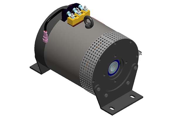
primary mover hydraulic pump made in china

We provide a variety of high-quality single and double-acting 12V hydraulic pumps. Choose from a selection of poly or steel reservoir sizing options. Our pumps are ideal for application with Dump Trailers and more. Browse our shop today and find the right hydraulic pump for your hydraulic circuit needs!

Hydraulic systems are in general members of the fluid power branch of power transmission. Hydraulic pumps are also members of the hydraulic power pack/hydraulic power unit family. Hydraulic units are encased mechanical systems that use liquids for hydraulics.
The hydraulic systems that hydraulic pumps support exist in a range of industries, among them agriculture, automotive manufacturing, defense contracting, excavation, and industrial manufacturing. Within these industries, machines and applications that rely on hydraulic pumps include airplane flaps, elevators, cranes, automotive lifts, shock absorbers, automotive brakes, garage jacks, off-highway equipment, log splitters, offshore equipment, hydraulic motors/hydraulic pump motors, and a wide range of other hydraulic equipment.
When designing hydraulic pumps, manufacturers have many options from which to choose in terms of material composition. Most commonly, they make the body of the pump–the gears, pistons, and hydraulic cylinders–from a durable metal material. This metal is one that that can hold up against the erosive and potentially corrosive properties of hydraulic fluids, as well as the wear that comes along with continual pumping. Metals like this include, among others, steel, stainless steel, and aluminum.
First, what are operating specifications of their customer? They must make sure that the pump they design matches customer requirements in terms of capabilities. These capabilities include maximum fluid flow, minimum and maximum operating pressure, horsepower, and operating speeds. Also, based on application specifications, some suppliers may choose to include discharge sensors or another means of monitoring the wellbeing of their hydraulic system.
Next, what is the nature of the space in which the pump will work? Based on the answer to this question, manufacturers will design the pump with a specific weight, rod extension capability, diameter, length, and power source.
Manufacturers must also find out what type of substance does the customer plan on running through the pumps. If the application calls for it, manufacturers can recommend operators add other substances to them in order to decrease the corrosive nature of certain hydraulic fluids. Examples of such fluids include esters, butanol, pump oils, glycols, water, or corrosive inhibitors. These substances differ in operating temperature, flash point, and viscosity, so they must be chosen with care.
All hydraulic pumps are composed in the same basic way. First, they have a reservoir, which is the section of the pump that houses stationary fluid. Next, they use hydraulic hoses or tubes to transfer this fluid into the hydraulic cylinder, which is the main body of the hydraulic system. Inside the cylinder, or cylinders, are two hydraulic valves and one or more pistons or gear systems. One valve is located at each end; they are called the intake check/inlet valve and the discharge check/outlet valve, respectively.
Hydraulic pumps operate under the principle of Pascal’s Law, which states the increase in pressure at one point of an enclosed liquid in equilibrium is equally transferred to all other points of said liquid.
To start, the check valve is closed, making it a normally closed (NC) valve. When the check is closed, fluid pressure builds. The piston forces the valves open and closes repeatedly at variable speeds, increasing pressure in the cylinder until it builds up enough to force the fluid through the discharge valve. In this way, the pump delivers sufficient force and energy to the attached equipment or machinery to move the target load.
When the fluid becomes pressurized enough, the piston withdraws long enough to allow the open check valve to create a vacuum that pulls in hydraulic fluid from the reservoir. From the reservoir, the pressurized fluid moves into the cylinder through the inlet. Inside the cylinder, the fluid picks up more force, which it carries over into the hydraulic system, where it is released through the outlet.
Piston pumps create positive displacement and build pressure using pistons. Piston pumps may be further divided into radial piston pumps and axial piston pumps.
Radial pumps are mostly used to power relatively small flows and very high-pressure applications. They use pistons arranged around a floating center shaft or ring, which can be moved by a control lever, causing eccentricity and the potential for both inward and outward movement.
Axial pumps, on the other hand, only allow linear motion. Despite this, they are very popular, being easier and less expensive to produce, as well as more compact in design.
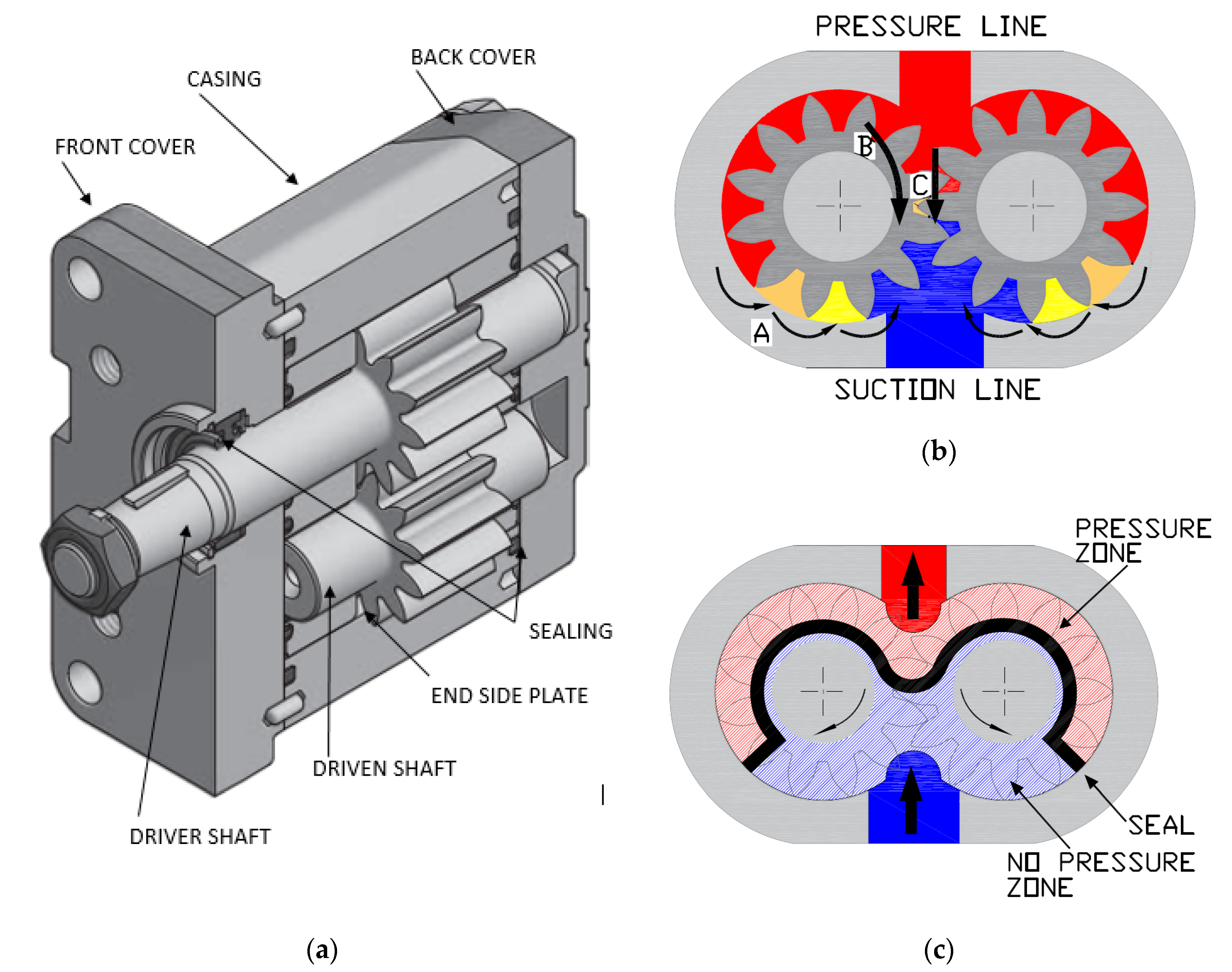
Gear pumps, or hydraulic gear pumps, create pressure not with pistons but with the interlocking of gear teeth. When teeth are meshed together, fluid has to travel around the outside of the gears, where pressure builds.
External gear pumps facilitate flow by enlisting two identical gears that rotate against each other. As liquid flows in, it is trapped by the teeth and forced around them. It sits, stuck in the cavities between the teeth and the casing, until it is so pressurized by the meshing of the gears that it is forced to the outlet port.
Internal gear pumps, on the other hand, use bi-rotational gears. To begin the pressurizing process, gear pumps first pull in liquid via a suction port between the teeth of the exterior gear, called the rotor, and the teeth of the interior gear, called the idler. From here, liquid travels between the teeth, where they are divided within them. The teeth continue to rotate and mesh, both creating locked pockets of liquid and forming a seal between the suction port and the discharge port. Liquid is discharged and power is transported once the pump head is flooded. Internal gears are quite versatile, usable with a wide variety of fluids, not only including fuel oils and solvents, but also thick liquids like chocolate, asphalt, and adhesives.
Various other types of hydraulic pumps include rotary vane pumps, centrifugal pumps, electric hydraulic pumps, hydraulic clutch pumps, hydraulic plunger pumps, hydraulic water pumps, hydraulic ram pumps, portable 12V hydraulic pumps, hydraulic hand pumps, and air hydraulic pumps.
Rotary vane pumps are fairly high efficiency pumps, though they are not considered high pressure pumps. Vane pumps, which are a type of positive-displacement pump, apply constant but adjustable pressure.
Centrifugal pumps use hydrodynamic energy to move fluids. They feature a rotating axis, an impeller, and a casing or diffuser. Most often, operators use them for applications such as petroleum pumping, sewage, petrochemical pumping, and water turbine functioning.
Electric hydraulic pumps are hydraulic pumps powered by an electric motor. Usually, the hydraulic pump and motor work by turning mechanisms like impellers in order to create pressure differentials, which in turn generate fluid movement. Nearly any type of hydraulic pump can be run with electricity. Most often, operators use them with industrial machinery.
Hydraulic clutch pumps help users engage and disengage vehicle clutch systems. They do so by applying the right pressure for coupling or decoupling shafts in the clutch system. Coupled shafts allow drivers to accelerate, while decoupled shafts allow drivers to decelerate or shift gears.
Hydraulic ram pumps are a type of hydraulic pump designed to harness hydropower, or the power of water, to elevate it. Featuring only two moving hydraulic parts, hydraulic ram pumps require only the momentum of water to work. Operators use hydraulic ram pumps to move water in industries like manufacturing, waste management and sewage, engineering, plumbing, and agriculture. While hydraulic ram pumps return only about 10% of the water they receive, they are widely used in developing countries because they do not require fuel or electricity.
Hydraulic water pumps are any hydraulic pumps used to transfer water. Usually, hydraulic water pumps only require a little bit of energy in the beginning, as the movement and weight of water generate a large amount of usable pressure.
Air hydraulic pumps are hydraulic pumps powered by air compressors. In essence, these energy efficient pumps work by converting air pressure into hydraulic pressure.
Hydraulic pumps are useful for many reasons. First, they are simple. Simple machines are always an advantage because they are less likely to break and easier to repair if they do. Second, because fluid is easy to compress and so quick to create pressure force, hydraulic pumps are very efficient. Next, hydraulic pumps are compact, which means they are easy to fit into small and oddly shaped spaces. This is especially true in comparison to mechanical pumps and electrical pumps, which manufacturers cannot design so compactly. Speaking of design, another asset of hydraulic pumps is their customizability. Manufacturers can modify them easily. Likewise, hydraulic pumps are very versatile, not only because they are customizable, but also because they can work in places where other types of pump systems can’t, such as in the ocean. Furthermore, hydraulic pumps can produce far more power than similarly sized electrical pumps. Finally, these very durable hydraulic components are much less likely to explode than some other types of components.
To make sure that your hydraulic pumps stay useful for a long time, you need to treat them with care. Care includes checking them on a regular basis for problems like insufficient fluid pressure, leaks, and wear and tear. You can use diagnostic technology like discharge sensors to help you with detect failures and measure discharge pressure. Checking vibration signals alone is often not enough.
To keep yourself and your workers safe, you need to always take the proper precautions when operating or performing maintenance and repairs on your hydraulic pumps. For example, you should never make direct contact with hydraulic fluid. For one, the fluid made be corrosive and dangerous to your skin. For two, even if the pump isn’t active at that moment, the fluid can still be pressurized and may potentially harm you if something goes wrong. For more tips on hydraulic pump care and operation, talk to both your supplier and OSHA (Occupational Safety and Health Administration).
Pumps that meet operating standards are the foundation of safe and effective operations, no matter the application. Find out what operating standards your hydraulic pumps should meet by talking to your industry leaders.
The highest quality hydraulic pumps come from the highest quality hydraulic pump manufacturers. Finding the highest quality hydraulic pump manufacturers can be hard, which is why we have we listed out some of our favorites on this page. All of those whom we have listed come highly recommended with years of experience. Find their information nestled in between these information paragraphs.
Once you have put together you list, get to browsing. Pick out three or four hydraulic pump supply companies to which you’d like to speak, then reach out to each of them. After you’ve spoken with representatives from each company, decide which one will best serve you, and get started on your project.
Kawasaki Precision Machinery (Suzhou) Ltd. was founded in Suzhou, Jiangsu, China in 2005 to manufacture and supply Kawasaki hydraulic components such as hydraulic pumps and motors in China. In 2015, the company started producing robots in addition to hydraulic products. This is Kawasaki’s second manufacturing facility for industrial robots after the first in Akashi, Japan.

In existing prime mover, as internal-combustion engine, steam turbine, though its working principle is distinguished to some extent, its essence all can be regarded a kind of transmission and transfer process of heat energy as, or to compression, expansion, the releasing course of heat energy.During this time, will consume a large amount of mineral resources, and ball ecological environment is caused serious destruction.Be necessary to develop new prime mover with traditional prime mover rare day by day in mineral resources, that ball ecological environment goes from bad to worse today, is that internal-combustion engine replaces by it.
The present invention is made up of prime mover main body, high-pressure service pump, liquid-container and generator, speed changer, high-pressure service pump starting power supply etc., sees accompanying drawing.Fig. 1 is a principle schematic; Fig. 2 is the overall structure schematic representation; Fig. 3 is for using schematic representation.Below in conjunction with accompanying drawing the present invention is described in detail.
Referring to Fig. 1, prime mover main body is made up of cylinder body 1, piston 2, connecting rod 3, bent axle 4, liquid injecting tube 5, liquid discharge pipe 6, tapping equipment 9.Open mortor operated valve 10 and start high-pressure service pump 7, liquid injects cylinder body 1 by liquid-container 8 through liquid injecting tube 5, because liquid has certain pressure and flow at high speed, so promote piston 2 actings, so and the straight line Driving force of generation is transformed into rotating force by connecting rod 3 bent axles 4.When piston moved to lower dead center, tapping equipment 9 was discharged liquid fast, simultaneously liquid injection port is closed, and enters liquid-container 8 through discharge pipe 6.Piston reset to top dead center was closed tapping equipment 9 simultaneously and was opened liquid injection port this moment, and carried out the circulation of a new round.Fluid flow is controlled by mortor operated valve 10, and controls the size of prime mover rotating speed and Driving force thus.
Fig. 2 is the overall structure schematic representation, is made up of liquid-container 8, mortor operated valve 10, high-pressure service pump 7, prime mover main body 12, generator 11, speed changer 13, high-pressure service pump starting power supply 14.At first starting power supply provides electric power to high-pressure service pump and make its operation, treat prime mover normal operation after, a part of power drives generator for electricity generation.Generator offers high-pressure service pump with electric power, and starting power supply is charged.Most of power of prime mover then offers load by speed changer.

Road planers, dredges, and other equipment require power from some type of engine to perform their designed function. Without a power take-off, it would be necessary to add a second engine to provide the power required to run hydraulic pumps and other driveline attached equipment.
Power take-offs allow mobile crushing plants, road milling machines, and other vehicles to perform auxiliary functions without needing an additional engine to power them. A PTO is a device (a mechanism) usually seated on the flywheel housing, which transfers power from the driveline (engine) to a secondary application. In most cases, this power transfer applies to a secondary shaft that drives a hydraulic pump, generator, air compressor, pneumatic blower, or vacuum pump.
PTO choice is critical to provide sufficient power to the auxiliary equipment without severely limiting the main function of the prime mover. Selection of a power take-off requires specific information relating to the application and the power needs of the secondary or driven component.
Keep in mind that these calculations only apply to PTOs that drives a hydraulic pump. In cases where power take-off is providing power to a different type of drive component, it will require the manufacturer’s specifications of the driven element.
Though they perform the same general function—transferring power from the primary drive shaft to a secondary drive shaft for a driven component—there are various PTO types available that serve specific industrial applications. These diversifications are why WPT Power supplies OEM’s units in agricultural, energy, forestry, and road building sectors, among others.
The design of the Type 2 PTO features a heavy-duty side loading capacity using sizeable spherical roller bearings. Actuation of this PTO can be either hydraulic or pneumatic. It is self-adjusting and removes the need for the pilot bearing inside the engine flywheel. Features include reduced maintenance, less chance of premature failures, and improved engine and bearing life since there is no direct loading to the crankshaft. Common applications for Type 2 PTOs include:
This PTO design eliminates the need for the pilot bearing while providing increased side loading or inline potential. Its engineering accommodates the most demanding requirements of high-loading diesel engines. Features include simple installation, reduced downtime, and improved engine service life. This style of PTO is used on inline applications with its hydraulic and air fittings. They are mounted near the bell housing instead of at the rear of the shaft like type 1 and type 2.
Power take-offs play an essential role in allowing for the transfer of power from a primary mover to a secondary or driven component without needing an additional separate engine. Various PTO types serve many applications, from smaller-scale operations to major industrial and construction projects. Choosing the correct PTO for a specific application is critical to the proper performance of the driven component.

China hydraulic pump manufacturers, hydraulic pumps and motors, hydraulic pump parts, piston pump parts, hydraulic pump, hydraulic spare parts, hydraulic piston pump, hydraulic vane pump, hydraulic gear pump, Hydraulic Motor,Pilot Pump, Charge Pump for Rexroth,Caterpillar,Vickers,Denison,Sauer,Kawasaki,Commercial,Linde,Parker,Liebherr,Komatsu,Eaton,Daikin,Kubota,Johndeer,Hitachi. T6C,T6D,T6E,45VQ,35VQ,25VQ,20VQ,V10,V20,Hydraulic Motor.
????Dry suction gas control valve is a hydraulic valve Zan, which is used to pump oil into savings, when the hydraulic equipment load, only the minimum flow through the pump; in the load, the full flow suction pump. As shown in Figure 10, this circuit can be omitted clutch between the pump and prime mover, then dropped the cost, no-load power consumption is also reduced, because the minimum flow loop through the insistence of the prime mover of power equipment. In addition, also declined pump noise at no-load. Dry suction valve circuit can be used in any vehicle driven by the engine"s hydraulic system switch, such as waste loading trucks and industrial equipment.
????Currently, work pressure has come near the gear pump piston pump, a combination of the gear pump load sensing program provides a possibility variables, which means between the gear pump and piston pump understand the original boundaries become increasingly blurred a. One of the determinants of reasonable pump selection program, is the capital of the entire system, compared with the price of expensive piston pump, gear pumps for its low cost, simple circuit, low demand characteristics of the filter into many occasions practicable The selection plan.
The primary construction machinery hydraulic power system depends on the volume of the pump power, when the volume drops to 72% when the power on the need for routine repair, replacement bearings and seals of aging, to replace or amend the friction pair gap beyond cooperation to make Its function rehabilitation.
Straight axis swashplate piston is divided into two kinds of pressure from the sucking oil type. Most oil pressure hydraulic pump selection have pressure tank, also with its own pump to pump up the oil cylinder oil inlet supply pressure of the oil. Since self-absorbing ability strong suction type pump, without external oil supply.
Rearward pressure hydraulic oil tank after each engine unit, it is necessary to use other hydraulic stains box arrives pressure, competence operate machinery. When the hydraulic pressure in the tank served as the lack of machinery, and hydraulic slip whip will be formed within the pull-off appearance, the formation of abnormal wear of the pump body board and return the platen. Selection charge pump supply piston pump, the use of 3000h, the operator need 1-2 times a day on the piston view to view the movement of the hydraulic pump is not working properly. Found cylinder speed drops or stuffy car, you should pump up the collapse of view, is not a view of the impeller edge scratching appearance, internal gear pump gap is not too large.
About Self-suction-type piston pump, the hydraulic oil tank must not fall below the lower limit of the oil standard, should adhere to meet the amount of hydraulic oil. The higher the cleanliness of hydraulic oil, the use of the longer life expectancy of the hydraulic pump.
The most important parts of piston bearing, if the bearing clearance presentation, you can not guarantee normal internal pump three pairs of friction pair gap, together will damage the hydrostatic bearing oil film thickness of each friction pair, down piston pump bearings use life expectancy. According to information supplied to the hydraulic pump factory, using the average life expectancy of bearings is 10000h, beyond this value will need to replace the new port.
A hydraulic pump is a machine that uses the power of fluid to move objects. The first pumps were invented in the seventeenth century, and they were mainly used for irrigation. Over time, however, hydraulic pumps have been used for a variety of other purposes, including mining, manufacturing, and moving objects.
A hydraulic pump is a machine that uses the pressure of fluids to move things. It works by using a piston and cylinder assembly to push and pull fluid through a series of tubes. The force of the fluid moving through the tubes creates a mechanical force that can be used to do work. There are two main types of hydraulic pumps: reciprocating and impeller. A reciprocating pump has a piston that moves back and forth inside the cylinder. The force created by this motion is used to push or pull fluid through the system. An impeller is a spinning cylinder, and it can be used as a reciprocating pump or as an aerator. The main components of a hydraulic pump are pistons, cylinders, valves, and pipes. They are all connected together in order to create a system that can move fluids. A piston is a cylinder that contains one or more chambers. The air inside these chambers can be compressed, and it is able to push the fluid up through an inlet port. The piston has a rod attached to it, and this rod connects to the cylinder head on its side. The cylinder head is the end of the cylinder that contains one or more pistons. The piston is used to push the fluid up through a port. It can also be used to pull fluid down from an outlet port. In order to use pistons, all of the needed components must be connected together. The cylinder head is usually connected to a valve, which can open and close the port where the fluid can go in or out.
A hydraulic pump is a machine used to move fluid. They are incredibly important in many industries and can be found in everything from cars to the military. They work by using the pressure of water or other fluids to push objects or materials around. This can be incredibly useful for things like moving oil around or filling up containers.
The main reason hydraulic pumps are so important is that they are incredibly versatile. They can be used for a variety of purposes, which means that they are often perfect for certain jobs. For example, a hydraulic pump can be used to move something heavy around, which is perfect for things like construction sites or factories.
Furthermore, hydraulic pumps are reliable machines. This means that they are often able to work even when there is some sort of problem with them. This makes them ideal for use in critical areas, such as the military or automotive industries.
Hydraulic pumps are machines that use hydraulic fluid to move objects or fluids. They come in a variety of types, each with its own advantages and disadvantages. Here is a brief introduction to five of the most common types of hydraulic pumps:
Motor-driven pumps are the most common type of pump. They use a motor to power a screw or gear that is connected to a piston in the cylinder of the pump. A small amount of fluid is pumped by the motor and this creates a vacuum that draws more fluid through the system.
Gear pumps use gears, cams, and a series of springs to move fluid. Gear pumps can be made to pump more fluid at a faster rate than motor-driven pumps.
Piston pumps are similar in operation to gear pumps. reciprocating pumps use pistons to move fluid. The most common type of reciprocating pump is the diaphragm pump. This type of pump has a piston and a diaphragm that moves up and down within the cylinder.
Siphon Pumps are typically used in potable water applications, such as sewage pumping. They can also be found in oil field operations and other industrial settings where a pump is needed to move liquids or gases. They are also commonly called “gravity pumps” because they operate in a very similar way to the movement of a siphon. Their operation is as follows: As fluid flows through the pump by gravity, a centrifugal force is generated and pushes the fluid out of the pump. Because the pump does not have a rotating shaft, the flow of fluid is not possible. Instead, the fluid flows around a circular chamber that causes the fluid to be pushed off at an angle from the axis. The fluid then moves out of the chamber and into a channel that connects to the system it is being used in. The fluid than either enters a reservoir or flows back into the pump. This process is called flow reversal.
Rotary pump: The rotary pump is similar to the piston pump, but it uses a rotating disk to move the fluid inside a cylinder. This type of pump is faster than the piston pump, but it requires more power (and thus costs more) to operate.
Pump designs can be classified by the size of the pump and its application. Pumps can be based on the movement of a piston or gears, or they may use a combination of these two methods. A rotary pump is a type of reciprocating pump that uses a rotating shaft to move the piston. The shaft can be designed to rotate in either direction, or it will rotate in only one direction. There are two ways to classify pumps by the size of the volume they can move. The first classification is based on the size of the piston, which determines how much fluid a single pump stroke will draw in or out. The second classification is based on the size of the pump chamber and how much fluid it can hold. A pump designed to move a small amount of fluid will have a small diameter piston. A pump designed to move large amounts of fluid will have a larger diameter piston and therefore a larger volume. The volume of the pump chamber is determined by the number of pumps that can be fitted into a space. The space between each of these pumps can be filled with either liquid or gas as an alternate way to move fluid. Pumps are used in a wide range of applications, from simple low-volume pumps to large-volume high-pressure pumps. Pumps are also used in the chemical, food, and beverage industries as a way to move fluids or chemicals.
Hydraulic pumps are an important part of modern industrial and commercial life. They are used in a wide range of applications, from water pumping to hydraulic power generation. The future of hydraulic pumps is bright, with many potential applications waiting to be developed. Here are 4 examples:
Hydraulic pumps could become increasingly important in the automotive industry as engines become more efficient and fuel prices continue to rise. Hydraulic pumps could also be used in larger vehicles, such as trucks and buses, to provide extra power or increase the capacity of the engine.
Hydraulic pumps could be used more often in construction and engineering projects, where they would be useful for tasks such as lifting heavy objects or moving large amounts of water or other fluid substances.
Hydraulic pumps could be used to generate electricity by using pressurized steam or water to turn turbines, like those found in power plants and factories.

The prime mover supplies the mechanical power to drive the hydraulic system. In the mobile hydraulics industry the prime mover we are most familiar with is the truck engine. The truck engine is frequently used to provide power through a Power Take-Off, through belts from the crankshaft pulley, or directly through a tubular driveshaft assembly. On some high horsepower systems an auxiliary, or “pony” engine might be used. In any case, the prime mover must be capable of providing the horsepower necessary to power the hydraulic system.
Double, or Triple Gear, power take-offs, found on dump trucks, refuse vehicles, wreckers, aerial bucket trucks, tank trucks, and truck mounted cranes, are the most widely used type of PTO because of their versatility. This type of PTO can be engaged by cable, air, electric solenoid, or mechanical levers and a wide variety of output shafts and mounting flanges allow for direct coupling of hydraulic pumps from major manufacturers. PTO output shaft speeds can be changed by changing the internal gear ratio of the PTO.
We will not attempt to go into PTO selection in this text. Suffice to say that when a power take-off is utilized as the source of power for the hydraulic system, it must meet the torque, horsepower, and speed requirements of the system.
Many refuse and snow control vehicles utilize a front-mounted hydraulic pump driven by a tubular driveshaft assembly from the harmonic balancer of the engine. This “live power” arrangement has the advantage of providing full engine torque on high-demand applications while eliminating the cost of the power take-off. The disadvantage to this type of installation is in the requirement to raise, or “core”, the radiator to allow passage for the driveshaft; extend the front frame rails; and fabricate a mounting bracket for the pump.
Another important consideration is driveshaft angularity. Not only is it necessary to keep the angle shallow—generally less than 7°—but also to keep the pump input shaft parallel to the engine crankshaft within 1-1/2°. Likewise, the yokes on each end of the shaft must be “in phase”, or aligned with each other. Failure to address any of these requirements will result in driveshaft vibration and damage to the pump.

Mechanical pumps serve in a wide range of applications such as pumping water from wells, aquarium filtering, pond filtering and aeration, in the car industry for water-cooling and fuel injection, in the energy industry for pumping oil and natural gas or for operating cooling towers and other components of heating, ventilation and air conditioning systems. In the medical industry, pumps are used for biochemical processes in developing and manufacturing medicine, and as artificial replacements for body parts, in particular the artificial heart and penile prosthesis.
When a pump contains two or more pump mechanisms with fluid being directed to flow through them in series, it is called a multi-stage pump. Terms such as two-stage or double-stage may be used to specifically describe the number of stages. A pump that does not fit this description is simply a single-stage pump in contrast.
In biology, many different types of chemical and biomechanical pumps have evolved; biomimicry is sometimes used in developing new types of mechanical pumps.
Pumps can be classified by their method of displacement into positive-displacement pumps, impulse pumps, velocity pumps, gravity pumps, steam pumps and valveless pumps. There are three basic types of pumps: positive-displacement, centrifugal and axial-flow pumps. In centrifugal pumps the direction of flow of the fluid changes by ninety degrees as it flows over an impeller, while in axial flow pumps the direction of flow is unchanged.
Some positive-displacement pumps use an expanding cavity on the suction side and a decreasing cavity on the discharge side. Liquid flows into the pump as the cavity on the suction side expands and the liquid flows out of the discharge as the cavity collapses. The volume is constant through each cycle of operation.
Positive-displacement pumps, unlike centrifugal, can theoretically produce the same flow at a given speed (rpm) no matter what the discharge pressure. Thus, positive-displacement pumps are constant flow machines. However, a slight increase in internal leakage as the pressure increases prevents a truly constant flow rate.
A positive-displacement pump must not operate against a closed valve on the discharge side of the pump, because it has no shutoff head like centrifugal pumps. A positive-displacement pump operating against a closed discharge valve continues to produce flow and the pressure in the discharge line increases until the line bursts, the pump is severely damaged, or both.
A relief or safety valve on the discharge side of the positive-displacement pump is therefore necessary. The relief valve can be internal or external. The pump manufacturer normally has the option to supply internal relief or safety valves. The internal valve is usually used only as a safety precaution. An external relief valve in the discharge line, with a return line back to the suction line or supply tank provides increased safety.
Rotary-type positive displacement: internal or external gear pump, screw pump, lobe pump, shuttle block, flexible vane or sliding vane, circumferential piston, flexible impeller, helical twisted roots (e.g. the Wendelkolben pump) or liquid-ring pumps
Drawbacks: The nature of the pump requires very close clearances between the rotating pump and the outer edge, making it rotate at a slow, steady speed. If rotary pumps are operated at high speeds, the fluids cause erosion, which eventually causes enlarged clearances that liquid can pass through, which reduces efficiency.
Hollow disk pumps (also known as eccentric disc pumps or Hollow rotary disc pumps), similar to scroll compressors, these have a cylindrical rotor encased in a circular housing. As the rotor orbits and rotates to some degree, it traps fluid between the rotor and the casing, drawing the fluid through the pump. It is used for highly viscous fluids like petroleum-derived products, and it can also support high pressures of up to 290 psi.
Vibratory pumps or vibration pumps are similar to linear compressors, having the same operating principle. They work by using a spring-loaded piston with an electromagnet connected to AC current through a diode. The spring-loaded piston is the only moving part, and it is placed in the center of the electromagnet. During the positive cycle of the AC current, the diode allows energy to pass through the electromagnet, generating a magnetic field that moves the piston backwards, compressing the spring, and generating suction. During the negative cycle of the AC current, the diode blocks current flow to the electromagnet, letting the spring uncompress, moving the piston forward, and pumping the fluid and generating pressure, like a reciprocating pump. Due to its low cost, it is widely used in inexpensive espresso machines. However, vibratory pumps cannot be operated for more than one minute, as they generate large amounts of heat. Linear compressors do not have this problem, as they can be cooled by the working fluid (which is often a refrigerant).
Reciprocating pumps move the fluid using one or more oscillating pistons, plungers, or membranes (diaphragms), while valves restrict fluid motion to the desired direction. In order for suction to take place, the pump must first pull the plunger in an outward motion to decrease pressure in the chamber. Once the plunger pushes back, it will increase the chamber pressure and the inward pressure of the plunger will then open the discharge valve and release the fluid into the delivery pipe at constant flow rate and increased pressure.
Pumps in this category range from simplex, with one cylinder, to in some cases quad (four) cylinders, or more. Many reciprocating-type pumps are duplex (two) or triplex (three) cylinder. They can be either single-acting with suction during one direction of piston motion and discharge on the other, or double-acting with suction and discharge in both directions. The pumps can be powered manually, by air or steam, or by a belt driven by an engine. This type of pump was used extensively in the 19th century—in the early days of steam propulsion—as boiler feed water pumps. Now reciprocating pumps typically pump highly viscous fluids like concrete and heavy oils, and serve in special applications that demand low flow rates against high resistance. Reciprocating hand pumps were widely used to pump water from wells. Common bicycle pumps and foot pumps for inflation use reciprocating action.
These positive-displacement pumps have an expanding cavity on the suction side and a decreasing cavity on the discharge side. Liquid flows into the pumps as the cavity on the suction side expands and the liquid flows out of the discharge as the cavity collapses. The volume is constant given each cycle of operation and the pump"s volumetric efficiency can be achieved through routine maintenance and inspection of its valves.
This is the simplest form of rotary positive-displacement pumps. It consists of two meshed gears that rotate in a closely fitted casing. The tooth spaces trap fluid and force it around the outer periphery. The fluid does not travel back on the meshed part, because the teeth mesh closely in the center. Gear pumps see wide use in car engine oil pumps and in various hydraulic power packs.
A screw pump is a more complicated type of rotary pump that uses two or three screws with opposing thread — e.g., one screw turns clockwise and the other counterclockwise. The screws are mounted on parallel shafts that have gears that mesh so the shafts turn together and everything stays in place. The screws turn on the shafts and drive fluid through the pump. As with other forms of rotary pumps, the clearance between moving parts and the pump"s casing is minimal.
Widely used for pumping difficult materials, such as sewage sludge contaminated with large particles, a progressing cavity pump consists of a helical rotor, about ten times as long as its width. This can be visualized as a central core of diameter x with, typically, a curved spiral wound around of thickness half x, though in reality it is manufactured in a single casting. This shaft fits inside a heavy-duty rubber sleeve, of wall thickness also typically x. As the shaft rotates, the rotor gradually forces fluid up the rubber sleeve. Such pumps can develop very high pressure at low volumes.
Named after the Roots brothers who invented it, this lobe pump displaces the fluid trapped between two long helical rotors, each fitted into the other when perpendicular at 90°, rotating inside a triangular shaped sealing line configuration, both at the point of suction and at the point of discharge. This design produces a continuous flow with equal volume and no vortex. It can work at low pulsation rates, and offers gentle performance that some applications require.
A peristaltic pump is a type of positive-displacement pump. It contains fluid within a flexible tube fitted inside a circular pump casing (though linear peristaltic pumps have been made). A number of rollers, shoes, or wipers attached to a rotor compresses the flexible tube. As the rotor turns, the part of the tube under compression closes (or occludes), forcing the fluid through the tube. Additionally, when the tube opens to its natural state after the passing of the cam it draws (restitution) fluid into the pump. This process is called peristalsis and is used in many biological systems such as the gastrointestinal tract.
Efficiency and common problems: With only one cylinder in plunger pumps, the fluid flow varies between maximum flow when the plunger moves through the middle positions, and zero flow when the plunger is at the end positions. A lot of energy is wasted when the fluid is accelerated in the piping system. Vibration and
Triplex plunger pumps use three plungers, which reduces the pulsation of single reciprocating plunger pumps. Adding a pulsation dampener on the pump outlet can further smooth the pump ripple, or ripple graph of a pump transducer. The dynamic relationship of the high-pressure fluid and plunger generally requires high-quality plunger seals. Plunger pumps with a larger number of plungers have the benefit of increased flow, or smoother flow without a pulsation damper. The increase in moving parts and crankshaft load is one drawback.
Car washes often use these triplex-style plunger pumps (perhaps without pulsation dampers). In 1968, William Bruggeman reduced the size of the triplex pump and increased the lifespan so that car washes could use equipment with smaller footprints. Durable high-pressure seals, low-pressure seals and oil seals, hardened crankshafts, hardened connecting rods, thick ceramic plungers and heavier duty ball and roller bearings improve reliability in triplex pumps. Triplex pumps now are in a myriad of markets across the world.
Triplex pumps with shorter lifetimes are commonplace to the home user. A person who uses a home pressure washer for 10 hours a year may be satisfied with a pump that lasts 100 hours between rebuilds. Industrial-grade or continuous duty triplex pumps on the other end of the quality spectrum may run for as much as 2,080 hours a year.
The oil and gas drilling industry uses massive semi trailer-transported triplex pumps called mud pumps to pump drilling mud, which cools the drill bit and carries the cuttings back to the surface.
One modern application of positive-displacement pumps is compressed-air-powered double-diaphragm pumps. Run on compressed air, these pumps are intrinsically safe by design, although all manufacturers offer ATEX certified models to comply with industry regulation. These pumps are relatively inexpensive and can perform a wide variety of duties, from pumping water out of bunds to pumping hydrochloric acid from secure storage (dependent on how the pump is manufactured – elastomers / body construction). These double-diaphragm pumps can handle viscous fluids and abrasive materials with a gentle pumping process ideal for transporting shear-sensitive media.
Devised in China as chain pumps over 1000 years ago, these pumps can be made from very simple materials: A rope, a wheel and a pipe are sufficient to make a simple rope pump. Rope pump efficiency has been studied by grassroots organizations and the techniques for making and running them have been continuously improved.
Impulse pumps use pressure created by gas (usually air). In some impulse pumps the gas trapped in the liquid (usually water), is released and accumulated somewhere in the pump, creating a pressure that can push part of the liquid upwards.
Instead of a gas accumulation and releasing cycle, the pressure can be created by burning of hydrocarbons. Such combustion driven pumps directly transmit the impulse from a combustion event through the actuation membrane to the pump fluid. In order to allow this direct transmission, the pump needs to be almost entirely made of an elastomer (e.g. silicone rubber). Hence, the combustion causes the membrane to expand and thereby pumps the fluid out of the adjacent pumping chamber. The first combustion-driven soft pump was developed by ETH Zurich.
It takes in water at relatively low pressure and high flow-rate and outputs water at a higher hydraulic-head and lower flow-rate. The device uses the water hammer effect to develop pressure that lifts a portion of the input water that powers the pump to a point higher than where the water started.
The hydraulic ram is sometimes used in remote areas, where there is both a source of low-head hydropower, and a need for pumping water to a destination higher in elevation than the source. In this situation, the ram is often useful, since it requires no outside source of power other than the kinetic energy of flowing water.
Rotodynamic pumps (or dynamic pumps) are a type of velocity pump in which kinetic energy is added to the fluid by increasing the flow velocity. This increase in energy is converted to a gain in potential energy (pressure) when the velocity is reduced prior to or as the flow exits the pump into the discharge pipe. This conversion of kinetic energy to pressure is explained by the
A practical difference between dynamic and positive-displacement pumps is how they operate under closed valve conditions. Positive-displacement pumps physically displace fluid, so closing a valve downstream of a positive-displacement pump produces a continual pressure build up that can cause mechanical failure of pipeline or pump. Dynamic pumps differ in that they can be safely operated under closed valve conditions (for short periods of time).
Such a pump is also referred to as a centrifugal pump. The fluid enters along the axis or center, is accelerated by the impeller and exits at right angles to the shaft (radially); an example is the centrifugal fan, which is commonly used to implement a vacuum cleaner. Another type of radial-flow pump is a vortex pump. The liquid in them moves in tangential direction around the working wheel. The conversion from the mechanical energy of motor into the potential energy of flow comes by means of multiple whirls, which are excited by the impeller in the working channel of the pump. Generally, a radial-flow pump operates at higher pressures and lower flow rates than an axial- or a mixed-flow pump.
These are also referred to as All fluid pumps. The fluid is pushed outward or inward to move fluid axially. They operate at much lower pressures and higher flow rates than radial-flow (centrifugal) pumps. Axial-flow pumps cannot be run up to speed without special precaution. If at a low flow rate, the total head rise and high torque associated with this pipe would mean that the starting torque would have to become a function of acceleration for the whole mass of liquid in the pipe system. If there is a large amount of fluid in the system, accelerate the pump slowly.
Mixed-flow pumps function as a compromise between radial and axial-flow pumps. The fluid experiences both radial acceleration and lift and exits the impeller somewhere between 0 and 90 degrees from the axial direction. As a consequence mixed-flow pumps operate at higher pressures than axial-flow pumps while delivering higher discharges than radial-flow pumps. The exit angle of the flow dictates the pressure head-discharge characteristic in relation to radial and mixed-flow.
Regenerative turbine pump rotor and housing, 1⁄3 horsepower (0.25 kW). 85 millimetres (3.3 in) diameter impeller rotates counter-clockwise. Left: inlet, right: outlet. .4 millimetres (0.016 in) thick vanes on 4 millimetres (0.16 in) centers
Also known as drag, friction, peripheral, traction, turbulence, or vortex pumps, regenerative turbine pumps are class of rotodynamic pump that operates at high head pressures, typically 4–20 bars (4.1–20.4 kgf/cm2; 58–290 psi).
The pump has an impeller with a number of vanes or paddles which spins in a cavity. The suction port and pressure ports are located at the perimeter of the cavity and are isolated by a barrier called a stripper, which allows only the tip channel (fluid between the blades) to recirculate, and forces any fluid in the side channel (fluid in the cavity outside of the blades) through the pressure port. In a regenerative turbine pump, as fluid spirals repeatedly from a vane into the side channel and back to the next vane, kinetic energy is imparted to the periphery,
As regenerative turbine pumps cannot become vapor locked, they are commonly applied to volatile, hot, or cryogenic fluid transport. However, as tolerances are typically tight, they are vulnerable to solids or particles causing jamming or rapid wear. Efficiency is typically low, and pressure and power consumption typically decrease with flow. Additionally, pumping direction can be reversed by reversing direction of spin.
Steam pumps have been for a long time mainly of historical interest. They include any type of pump powered by a steam engine and also pistonless pumps such as Thomas Savery"s or the Pulsometer steam pump.
Recently there has been a resurgence of interest in low power solar steam pumps for use in smallholder irrigation in developing countries. Previously small steam engines have not been viable because of escalating inefficiencies as vapour engines decrease in size. However the use of modern engineering materials coupled with alternative engine configurations has meant that these types of system are now a cost-effective opportunity.
Valveless pumping assists in fluid transport in various biomedical and engineering systems. In a valveless pumping system, no valves (or physical occlusions) are present to regulate the flow direction. The fluid pumping efficiency of a valveless system, however, is not necessarily lower than that having valves. In fact, many fluid-dynamical systems in nature and engineering more or less rely upon valveless pumping to transport the working fluids therein. For instance, blood circulation in the cardiovascular system is maintained to some extent even when the heart"s valves fail. Meanwhile, the embryonic vertebrate heart begins pumping blood long before the development of discernible chambers and valves. Similar to blood circulation in one direction, bird respiratory systems pump air in one direction in rigid lungs, but without any physiological valve. In microfluidics, valveless impedance pumps have been fabricated, and are expected to be particularly suitable for handling sensitive biofluids. Ink jet printers operating on the piezoelectric transducer principle also use valveless pumping. The pump chamber is emptied through the printing jet due to reduced flow impedance in that direction and refilled by capillary action.
Examining pump repair records and mean time between failures (MTBF) is of great importance to responsible and conscientious pump users. In view of that fact, the preface to the 2006 Pump User"s Handbook alludes to "pump failure" statistics. For the sake of convenience, these failure statistics often are translated into MTBF (in this case, installed life before failure).
In early 2005, Gordon Buck, John Crane Inc.’s chief engineer for field operations in Baton Rouge, Louisiana, examined the repair records for a number of refinery and chemical plants to obtain meaningful reliability data for centrifugal pumps. A total of 15 operating plants having nearly 15,000 pumps were included in the survey. The smallest of these plants had about 100 pumps; several plants had over 2000. All facilities were located in the United States. In addition, considered as "new", others as "renewed" and still others as "established". Many of these plants—but not all—had an alliance arrangement with John Crane. In some cases, the alliance contract included having a John Crane Inc. technician or engineer on-site to coordinate various aspects of the program.
Not all plants are refineries, however, and different results occur elsewhere. In chemical plants, pumps have historically been "throw-away" items as chemical attack limits life. Things have improved in recent years, but the somewhat restricted space available in "old" DIN and ASME-standardized stuffing boxes places limits on the type of seal that fits. Unless the pump user upgrades the seal chamber, the pump only accommodates more compact and simple versions. Without this upgrading, lifetimes in chemical installations are generally around 50 to 60 percent of the refinery values.
Unscheduled maintenance is often one of the most significant costs of ownership, and failures of mechanical seals and bearings are among the major causes. Keep in mind the potential value of selecting pumps that cost more initially, but last much longer between repairs. The MTBF of a better pump may be one to four years longer than that of its non-upgraded counterpart. Consider that published average values of avoided pump failures range from US$2600 to US$12,000. This does not include lost opportunity costs. One pump fire occurs per 1000 failures. Having fewer pump failures means having fewer destructive pump fires.
As has been noted, a typical pump failure, based on actual year 2002 reports, costs US$5,000 on average. This includes costs for material, parts, labor and overhead. Extending a pump"s MTBF from 12 to 18 months would save US$1,667 per year — which might be greater than the cost to upgrade the centrifugal pump"s reliability.
Pumps are used throughout society for a variety of purposes. Early applications includes the use of the windmill or watermill to pump water. Today, the pump is used for irrigation, water supply, gasoline supply, air conditioning systems, refrigeration (usually called a compressor), chemical movement, sewage movement, flood control, marine services, etc.
Because of the wide variety of applications, pumps have a plethora of shapes and sizes: from very large to very small, from handling gas to handling liquid, from high pressure to low pressure, and from high volume to low volume.
Typically, a liquid pump can"t simply draw air. The feed line of the pump and the internal body surrounding the pumping mechanism must first be filled with the liquid that requires pumping: An operator must introduce liquid into the system to initiate the pumping. This is called priming the pump. Loss of prime is usually due to ingestion of air into the pump. The clearances and displacement ratios in pumps for liquids, whether thin or more viscous, usually cannot displace air due to its compressibility. This is the case with most velocity (rotodynamic) pumps — for example, centrifugal pumps. For such pumps, the position of the pump should always be lower than the suction point, if not the pump should be manually filled with liquid or a secondary pump should be used until all air is removed from the suction line and the pump casing.
Positive–displacement pumps, however, tend to have sufficiently tight sealing between the moving parts and the casing or housing of the pump that they can be described as self-priming. Such pumps can also serve as priming pumps, so-called when they are used to fulfill that need for other pumps in lieu of action taken by a human operator.
One sort of pump once common worldwide was a hand-powered water pump, or "pitcher pump". It was commonly installed over community water wells in the days before piped water supplies.
In parts of the British Isles, it was often called the parish pump. Though such community pumps are no longer common, people still used the expression parish pump to describe a place or forum where matters of local interest are discussed.
Because water from pitcher pumps is drawn directly from the soil, it is more prone to contamination. If such water is not filtered and purified, consumption of it might lead to gastrointestinal or other water-borne diseases. A notorious case is the 1854 Broad Street cholera outbreak. At the time it was not known how cholera was transmitted, but physician John Snow suspected contaminated water and had the handle of the public pump he suspected removed; the outbreak then subsided.
Modern hand-operated community pumps are considered the most sustainable low-cost option for safe water supply in resource-poor settings, often in rural areas in developing countries. A hand pump opens access to deeper groundwater that is often not polluted and also improves the safety of a well by protecting the water source from contaminated buckets. Pumps such as the Afridev pump are designed to be cheap to build and install, and easy to maintain with simple parts. However, scarcity of spare parts for these type of pumps in some regions of Africa has diminished their utility for these areas.
Multiphase pumping applications, also referred to as tri-phase, have grown due to increased oil drilling activity. In addition, the economics of multiphase production is attractive to upstream operations as it leads to simpler, smaller in-field installations, reduced equipment costs and improved production rates. In essence, the multiphase pump can accommodate all fluid stream properties with one piece of equipment, which has a smaller footprint. Often, two smaller multiphase pumps are installed in series rather than having just one massive pump.
A rotodynamic pump with one single shaft that requires two mechanical seals, this pump uses an open-type axial impeller. It is often called a Poseidon pump, and can be described as a cross between an axial compressor and a centrifugal pump.
The twin-screw pump is constructed of two inter-meshing screws that move the pumped fluid. Twin screw pumps are often used when pumping conditions contain high gas volume fractions and fluctuating inlet conditions. Four mechanical seals are required to seal the two shafts.
These pumps are basically multistage centrifugal pumps and are widely used in oil well applications as a method for artificial lift. These pumps are usually specified when the pumped fluid is mainly liquid.
A buffer tank is often installed upstream of the pump suction nozzle in case of a slug flow. The buffer tank breaks the energy of the liquid slug, smooths any fluctuations in the incoming flow and acts as a sand trap.
As the name indicates, multiphase pumps and their mechanical seals can encounter a large variation in service conditions such as changing process fluid composition, temperature variations, high and low operating pressures and exposure to abrasive/erosive media. The challenge is selecting the appropriate mechanical seal arrangement and support system to ensure maximized seal life and its overall effectiveness.
Pumps are commonly rated by horsepower, volumetric flow rate, outlet pressure in metres (or feet) of head, inlet suction in suction feet (or metres) of head.
From an initial design point of view, engineers often use a quantity termed the specific speed to identify the most suitable pump type for a particular combination of flow rate and head.
The power imparted into a fluid increases the energy of the fluid per unit volume. Thus the power relationship


 8613371530291