
what causes hydraulic pump cavitation quotation

The second leading cause of hydraulic pump failure, behind contamination, is cavitation. Cavitation is a condition that can also potentially damage or compromise your hydraulic system. For this reason, understanding cavitation, its symptoms, and methods of prevention are critical to the efficiency and overall health of not just your hydraulic pump, but your hydraulic system as a whole.
The product of excessive vacuum conditions created at the hydraulic pump’s inlet (supply side), cavitation is the formation, and collapse of vapors within a hydraulic pump. High vacuum creates vapor bubbles within the oil, which are carried to the discharge (pressure) side. These bubbles then collapse, thus cavitation.
This type of hydraulic pump failure is caused by poor plumbing, flow restrictions, or high oil viscosity; however, the leading cause of cavitation is poor plumbing. Poor plumbing is the result of incorrectly sized hose or fittings and or an indirect (not straight or vertical) path from the pump to the reservoir. Flow restrictions, for example, include buildup in the strainer or the use of an incorrect length of hose or a valve that is not fully open. Lastly, high oil viscosity—or oil that is too viscous—will not flow easily to the pump. Oil viscosity must be appropriate for the climate and application in which the hydraulic pump is being used.
The greatest damage caused by cavitation results from the excessive heat generated as the vapor bubbles collapse under the pressure at the pump outlet or discharge side. On the discharge side, these vapor bubbles collapse as the pressure causes the gases to return to a liquid state. The collapses of these bubbles result in violent implosions, drawing surrounding material, or debris, into the collapse. The temperature at the point of implosion can exceed 5,000° F. Keep in mind that in order for these implosions to happen, there must be high vacuum at the inlet and high pressure at the outlet.
Cavitation is usually recognized by sound. The pump will either produce a “whining” sound (more mild conditions) or a “rattling” sound (from intense implosions) that can sound like marbles in a can. If you’re hearing either of these sounds, you first need to determine the source. Just because you hear one of these two sounds doesn’t guarantee that your hydraulic pump is the culprit.
To isolate the pump from the power take-off (PTO) to confirm the source, remove the bolts that connect the two components and detach the pump from the PTO. Next, run the PTO with no pump and see if the sound is still present. If not, it is safe to assume your hydraulic pump is the problem.
Another sign you may be experiencing cavitation is physical evidence. As part of your general maintenance, you should be inspecting and replacing the hydraulic oil filter"s elements at regular intervals based on the duty cycle of the application and how often it is used. If at any time during the inspection and replacement of these elements you find metallic debris, it could be a sign that you’re experiencing cavitation in the pump.
The easiest way to determine the health of your complete hydraulic circuit is to check the filter. Every system should have a hydraulic oil filter somewhere in-line. Return line filters should be plumbed in the, you guessed it, return line from the actuator back to tank—as close to the tank as possible. As mentioned earlier, this filter will have elements that should be replaced at regular intervals. If you find metallic debris, your pump could be experiencing cavitation. You’ll then need to flush the entire system and remove the pump for inspection.
Conversely, if you’ve already determined the pump to be damaged, you should remove the filter element, cut it open, and inspect it. If you find a lot of metal, you’ll need to flush the entire system and keep an eye on the other components that may be compromised as a result.
Once cavitation has been detected within the hydraulic pump, you’ll need to determine the exact cause of cavitation. If you don’t, cavitation can result in pump failure and compromise additional components—potentially costing you your system.
Since the pump is fed via gravity and atmospheric pressure, the path between the reservoir and the pump should be as vertical and straight as possible. This means that the pump should be located as close to the reservoir as is practical with no 90-degree fittings or unnecessary bends in the supply hose. Whenever possible, be sure to locate the reservoir above the pump and have the largest supply ports in the reservoir as well. And don"t forget, ensure the reservoir has a proper breather cap or is pressurized (3–5 PSI), either with an air system or pressure breather cap.
Be sure the supply line shut-off valve (if equipped) is fully open with no restrictions. This should be a “full-flow” ball valve with the same inside diameter (i.d.) as the supply hose. If feasible, locate a vacuum gauge that can be T’d into the supply line and plumb it at the pump inlet port. Activate the PTO and operate a hydraulic function while monitoring the gauge. If it reads >5 in. Hg, shut it off, and resume your inspection.
A hose with an inner bladder vulcanized to a heavy spiral is designed to withstand vacuum conditions as opposed to outward pressure. The layline will also denote the size of the hose (i.d.). You can use Muncie Power’s PPC-1 hydraulic hose calculator to determine the optimal diameter for your particular application based on operating flows.
Another consideration, in regards to the inlet plumbing, is laminar flow. To reduce noise and turbulence at the pump inlet, the length of the supply hose should be at least 10 times its diameter. This means that any type of shut-off valve or strainer at the reservoir should be at least 10 diameters from the pump inlet. A flared, flange-style fitting at the pump inlet can also reduce pump noise by at least 50 percent compared to a SAE, JIC, or NPT fitting.
Selecting the proper viscosity of hydraulic fluid for your climate and application is also critical. Oil that is too viscous will not flow as easily to the pump. Consult your local hydraulic oil supplier for help selecting the optimal fluid viscosity.
By maintaining a regular maintenance schedule, remaining vigilant for any signs or symptoms, and taking preventative measures, the good news is that you should be able to prevent cavitation and experience efficient operation for the duration of your pump’s lifespan.
Poor plumbing is the leading cause of cavitation and can be prevented by selecting a properly sized hose, choosing the appropriate fittings, ensuring the most direct, straight routing from the pump to the reservoir, etc.
A variety of factors within the system could produce such a vacuum. When fluid enters the hydraulic pump and is compressed, the small air bubbles implode on a molecular level. Each implosion is extremely powerful and can remove material from the inside of the pump until it is no longer functional. Cavitation can destroy brand new pumps in a matter of minutes, leaving signs of physical damage including specific wear patterns. The process of cavitation destroying a hydraulic pump also has a distinctly audible sound similar to a growl.
The good news is that cavitation need not be a common problem in hydraulic systems. A few design flaws are largely responsible for causing cavitation: improper configuration of pump suction lines and the use of suction-line filters or strainers. To prevent these causes of cavitation and ensure the creation of a quality hydraulic system with a long, productive life, seven design elements must be properly executed:
In addition to improper pump suction-line configurations, suction-line filters or strainers can be a leading cause of cavitation. These filters are often placed under the oil reservoir, and thus are rarely serviced properly due to their inconvenient location. With this configuration, the entire reservoir has to be drained and disassembled in order to the reach the filter, so this necessary task is often neglected. As the filter becomes increasingly full of debris over time due to a lack of regular maintenance, not enough fluid will flow to the pump, and cavitation will occur.
Such causes of cavitation can be prevented using a series of correct design practices based on the specific needs and functions of a hydraulic system. Many systems are unique, so an experienced engineer with a firm grasp on each of these concepts must ensure the proper installation and maintenance of a hydraulic system.
Air bubbles in hydraulic fluid first originate is in the reservoir. New oil being introduced into the reservoir can cause turbulent flow, stirring up the oil and introducing air into the fluid, which can lead to cavitation. A correctly designed reservoir tank will prevent this issue.
The size of the tank and the amount of fluid that needs to rest before being extracted depends on the amount of system flow. However, a minimum 4 to 1 tank capacity to flow rate ratio is recommended — four times the oil available in the reservoir at any given time than is needed for extraction to send to the pump. This ensures that the pump will receive clean oil and the oil spends enough time in the reservoir for air bubbles and impurities to work their way out.
Beyond properly designing the reservoir itself, it’s important to include the correct accessories to ensure proper functionality. The breather filter is perhaps the most important accessory for maintaining the correct conditions for the hydraulic fluid in the tank.
When fluid is drawn from the reservoir by the pump, and an equal amount isn"t returned, the oil level will drop. To regulate the pressure and prevent forming a vacuum, air needs to be introduced to the tank to occupy the extra volume created upon removal of the oil. A breather filter performs this function, which helps avoid cavitation.
Incorrect design and configuration of suction lines is the primary cause of cavitation in hydraulic systems. For this reason, it’s crucial to use correct design practices when designing the suction lines, such as using the proper line size, minimizing fittings on the line, and properly sizing the ball valve to handle the amount of flow through the line.
The size of a suction line should be large enough for the liquid’s area to flow through at the correct rate and in the correct amount. Because the pump needs to be constantly supplied with oil, it becomes obvious how a line that’s too small could prevent this essential function. The exact specifications of a suction line in terms of length and width can’t be determined in a general sense — it requires a skilled engineer with a firm grasp of the process to make the correct decision on this specification.
Another best practice to consider when configuring suction lines is to include a lock on the suction ball valve, preventing it from being accidentally closed or left partially closed during the pump’s operation. Shutting off the flow of a suction line during pump operation will have cataclysmic effects on the system.
For example, the oil can be filtered upon entering the reservoir tank rather than when leaving the tank. Or a off-line (kidney loop) filtration system can be used to pull the oil out of the tank, filter it, and reinsert it before it’s extracted and sent to a hydraulic pump. These solutions allow for greater ease of maintenance and lower the chance of system failure.
A key aspect of a hydraulic system is a pump that’s properly sized to handle the flow rate and amount of fluid in the system. Again, this decision must be made by an experienced engineer with a good understanding of the entire process. A pump’s size can be determined by incorporating several variables of the process into a standard equation while also considering unique application conditions.
Another key element within a hydraulic system is to maintain the proper fluid temperature. If the hydraulic fluid gets too cold, it can become too viscous, increasing pressure drop in fluid lines and eventual cavitation in the pump. On the other hand, overheated hydraulic fluid can become too thin, compromising its ability to lubricate the hydraulic pump.
To regulate the temperature of the fluid, electric heating elements can be placed in the reservoir to keep the fluid at the ideal temperature of 110°F. Hydraulic systems often heat themselves naturally, so it’s also important to monitor for temperatures in excess of 110° and provide a heat exchanger or operate the system at reduced capacity.
Most systems use a flooded suction design, meaning that the pump is placed below the oil level to achieve net positive suction. The oil comes out of the reservoir above the location of the pump, which means gravity is used to assist in creating pressure into the pump and suction line. This represents the ideal configuration for a pump in a hydraulic system.
The alternative to this layout is non-flooded suction, in which the pump is placed on top of the tank. This configuration is often used to save space in a system with a limited footprint, but results in several disadvantages. For instance, the pump has to perform the extra work of pulling the oil up against gravity to create a vacuum and then pump the fluid out, which inherently creates restrictions by working against gravity. Also, certain types of pumps will function poorly in a non-flooded suction layout. In these cases, a charge pump can be used to provide positive pressure in the pump suction line.
If each of these design elements is carefully considered while engineering a hydraulic system, the risk of cavitation damaging or destroying hydraulic pumps should decrease significantly. Latest from Valin"s Blog
Frequently occurring in pumping applications, cavitation creates bubbles or vapor cavities in a liquid as a result of rapid changes in pressure. These liquid-free voids typically form in low-pressure zones and can burst when subjected to high pressures, sending powerful shockwaves throughout the entire application.
Manufacturers in the chemical processing, food processing, and petroleum industries must consider the risk of cavitation when designing machinery in order to avoid unwanted noise, vibration, and component damage.
Cavitation decreases an application’s efficiency over time and puts repeated stress on critical pump parts, shortening their overall lifespan. Shockwaves can cause significant damage to the pump, which in turn leads to premature valve failure, decreased flow pressure, and, ultimately, breakage. If you’re experiencing any of these issues with your pumping application, our in-house pump experts can help.
There are two types of cavitation that may occur in reciprocating positive displacement applications: suction and discharge. Suction cavitation occurs ahead of the suction stroke, when the pump is starved of flow, either from being in a high-vacuum or low-pressure environment. The opening of the valve is delayed by inertia, causing a lower flow rate on the suction side and resulting in expansion, pressure decrease, and the formation of bubbles close to the plunger.
Discharge cavitation occurs when the pump’s discharge pressure is too high. Under these conditions, it’s difficult for the fluid to flow out of the pump. Instead, it continues moving at high velocities inside the working chamber, forming bubbles in the process.
When working with pumping applications in a processing industry, cavitation should always be kept in mind; being able to recognize the warning signs and identify the root causes of cavitation in your machinery can significantly reduce the risk of long-term damages, saving both time and money.
Triangle Pump Components has nearly a century of experience assisting clients with pump issues such as cavitation. Our pump components are designed to preserve expensive parts such as crankshafts and power frames by transferring the majority of wear to less expensive, more expendable parts such valves, plungers, and packing.
Across any pumping system there is a complex pressure profile. This arises from many properties of the system: the throughput rate, head pressure, friction losses both inside the pump and across the system as a whole. In a centrifugal pump, for example, there is a large drop in pressure at the impeller’s eye and an increase within its vanes (see Figure 1). In a positive displacement pump, the fluid’s pressure drops when it is drawn, essentially from rest, into the pumping chamber. The fluid’s pressure increases again when it is expelled.
If the pressure of the fluid at any point in a pump is lower than its vapour pressure, it will literally boil, forming vapour bubbles within the pump. The formation of bubbles leads to a loss in throughput and increased vibration and noise. However, when the bubbles pass on into a section of the pump at higher pressure, the vapour condenses and the bubbles implode, releasing, locally, damaging amounts of energy. This can cause severe erosion of pump components.
To avoid cavitation, it is important to match your pump to the fluid, system and application. This is a complex area and you are advised to discuss your application with the pump supplier.
The obvious symptoms of cavitation are noise and vibration. When bubbles of vapour implode they can make a series of bubbling, crackling, sounds as if gravel is rattling around the pump housing or pipework. In addition to the noise, there may be unusual vibrations not normally experienced when operating the pump and its associated equipment.
With centrifugal pumps, the discharge pressure will be reduced from that normally observed or predicted by the pump manufacturer. In positive displacement pumps, cavitation causes a reduction in flow rather than head or pressure because vapour bubbles displace fluid from the pumping chamber reducing its capacity.
Power consumption may also be affected under the erratic conditions associated with cavitation. It may fluctuate and will be higher to achieve the same throughput. Also, in extreme cases, when cavitation is damaging pump components, you may observe debris in the discharged liquid from pump components including seals and bearings.
Under the conditions favouring cavitation, vapour bubbles are seeded by surface defects on metal components within the pump: for example, the impeller of a centrifugal pump or the piston or gear of a positive displacement pump. When the bubbles are subjected to higher pressures at discharge they implode energetically, directing intense and highly focussed shockwaves, as high as 10,000MPa, at the metal surface on which the bubbles had nucleated. Since the bubbles preferentially form on tiny imperfections, more erosion occurs at these points.
When a pump is new, it is more resistant to cavitation because the metal components have few surface imperfections to seed bubble formation. There may be a period of operation before any damage occurs but, eventually, as surface defects accumulate, cavitation damage will become increasingly apparent.
Classic (or classical) cavitation occurs when a pump is essentially starved of fluid (it is also called vaporization cavitation and inadequate NPSH-A cavitation). This can occur because of clogged filters, narrow upstream pipework or restricting (perhaps partially closed) valves. If the pump is fed from a tank, the level of liquid (or pressure above it) may have fallen below a critical level.
In a centrifugal pump, ‘classic’ cavitation occurs at the eye of the impeller as it imparts velocity on the liquid (see Figure 1). In a positive displacement pump, it can happen in an expanding piston, plunger or suction-side chamber in a gear pump. Reciprocating pumps, for example, should not be used in self-priming applications without careful evaluation of the operating conditions. During the suction phase, the pump chamber could fill completely with vapour, which then condenses in a shockwave during the compression phase.
Vane Passing Syndrome, also known as vane syndrome, is a type of cavitation that occurs when the spacing between the vanes of a centrifugal pump’s impeller and its housing is too small, leading to turbulent and restricted flow and frictional heating. The pumped liquid expands as it passes beyond the constriction and cavitation occurs.
Suction recirculation (also called internal recirculation) is a potential problem observed with centrifugal pumps when operated at reduced flow rate. This might occur, for example, when a discharge valve has been left partially closed or when the pump is being operated at a flow below the minimum recommended by the pump manufacturer. Under these conditions, liquid may be ejected from the vanes back towards the suction pipe rather than up the discharge port. This causes turbulence and pressure pulses throughout the pump which may lead to intense cavitation.
Air can be sucked into a pumping system through leaking valves or other fittings and carried along, dissolved in the liquid. Air bubbles may form within the pump on the suction side, collapsing again with the higher pressure on the discharge side. This can create shock waves through the pump.
To avoid cavitation, the pressure of the fluid must be maintained above its vapour pressure at all points as it passes through the pump. Manufacturers of centrifugal pumps specify a property referred to as the Net Positive Suction Head Required or NPSH-R – this is the minimum recommended fluid inlet pressure. The documentation supplied with your pump may contain charts showing how NPSH-R varies with flow.
In fact, NPSH-R is defined as the suction-side pressure at which cavitation reduces the discharge pressure by 3%: a pump is already experiencing cavitation at this pressure. Consequently, it is important to build in a safety margin (about 0.5 to 1m) to take account of this and other factors such as:
Positive displacement pumps require an inlet pressure to be a certain differential greater than the vapour pressure of the fluid to avoid cavitation during the suction phase. This is discussed in terms of Net Positive Inlet Pressure (NPIP) in a similar manner to NPSH for centrifugal pumps. NPSH is measured in feet or meters and NPIP is measured in pressure such as psi or bar. When converted to the same units, NPSH and NPIP are the same. Manufacturers may quote NPIP-R as the recommended inlet pressure and provide charts showing how it varies with pump speed. The available or actual inlet pressure on an operating system is termed NPIP-A.
Cavitation is a potentially damaging effect that occurs when the pressure of a liquid drops below its saturated vapour pressure. Under these conditions it forms bubbles of vapour within the fluid. If the pressure is increased again, the bubbles implode, releasing damaging shockwaves. This can cause severe erosion of components. A common example of cavitation is when a centrifugal pump is starved of feed: vapour bubbles form in the eye of the impeller as it imparts velocity on the liquid and collapse again on the discharge side of the vanes as the fluid pressure increases. This can lead to damage to an impeller’s vanes, seal or bearing. Cavitation can also occur in positive displacement pumps such as gear pumps and plunger pumps.
With a centrifugal pump, ensure that NPSH-A is at least 0.5m greater than NPSH-R during operation. For example, if the pump is fed from a tank, ensure that the level of liquid in the tank (or pressure above it) is sufficient. For a positive displacement pump, make sure that the inlet pressure complies with the manufacturer’s NPIP requirements.

Two leading causes why hydraulic pumps usually fail are: (1) contamination and (2) cavitation. In order to prevent any potential damage to your entire hydraulic system, it’s imperative to understand cavitation, the indications or symptoms from your system it is occurring, as well as the preventive measures.
How does cavitation happen exactly? It starts when vapor bubbles in the oil are created due to high vacuum. When these vapor bubbles are carried and collapsed on the pump outlet (discharge side), cavitation happens.
Make Sure Oil flow Paths are Straight – Hydraulic pumps are being supplied via atmospheric pressure and gravity, so it’s ideal to place the reservoir above it. Make sure that the path is as straight and vertical as possible. Keep an eye on bent or twisted supply hose.
Check Laminar Flow – If you’re hearing turbulence or noise in pump inlet, make sure that the supply hose length is the correct ratio to its diameter. A flange-style, flared fitting in the pump inlet can also help in eliminating pump noise.
Check Proper Viscosity – It"s important to choose the hydraulic fluid with appropriate viscosity for your application and climate. Consult with your supplier for professional help in choosing the optimal fluid viscosity.
With regular maintenance, keeping an eye on symptoms, and taking preventive measures, you’d be able to avoid cavitation and expect efficient operation from your hydraulic pumps.

Have a pump that makes popping sounds, or sounds like it"s pumping marbles? If so, you may have a cavitation problem. Pump cavitation can cause a number of issues for your pumping system, including excess noise and energy usage, not to mention serious damage to the pump itself.
Simply defined, cavitation is the formation of bubbles or cavities in liquid, developed in areas of relatively low pressure around an impeller. The imploding or collapsing of these bubbles trigger intense shockwaves inside the pump, causing significant damage to the impeller and/or the pump housing.
When a pump is under low pressure or high vacuum conditions, suction cavitation occurs. If the pump is "starved" or is not receiving enough flow, bubbles or cavities will form at the eye of the impeller. As the bubbles carry over to the discharge side of the pump, the fluid conditions change, compressing the bubble into liquid and causing it to implode against the face of the impeller.
An impeller that has fallen victim to suction cavitation will have large chunks or very small bits of material missing, causing it to look like a sponge. Damage to the impeller appears around the eye of the impeller when suction cavitation is present.
When a pump"s discharge pressure is extremely high or runs at less than 10% of its best efficiency point (BEP), discharge cavitation occurs. The high discharge pressure makes it difficult for the fluid to flow out of the pump, so it circulates inside the pump. Liquid flows between the impeller and the housing at very high velocity, causing a vacuum at the housing wall and the formation of bubbles.
As with suction cavitation, the implosion of those bubbles triggers intense shockwaves, causing premature wear of the impeller tips and pump housing. In extreme cases, discharge cavitation can cause the impeller shaft to break.
Reference the pump"s curve - Use a pressure gauge and/or a flowmeter to understand where your pump is operating on the curve. Make sure it is running at its best efficiency point. Running the pump off its best efficiency point not only causes excess recirculation, expect excessive heat, radial loads, vibration, high seal temperatures, and lowered efficiency.
Re-evaluate pipe design - Ensure the path the liquid takes to get to and from your pump is ideal for the pump"s operating conditions. Designs with inverted “U”s on the suction side can trap air, while designs with a 90° immediately before the pump can cause turbulence inside the pump. Both result in suction problems and pump cavitation.
For more information about how to detect and prevent pump cavitation, be sure to check out our post: Technologies To Detect and Prevent Pump Cavitation.
Cavitation is a common problem in pumping systems, but with proper pump sizing, pipe design, and care of filters and strainers, damage to pumps and their impellers can be largely avoided.

While it’s common for people to think of a pump’s inlet as sucking in oil, in reality, it is atmospheric pressure doing the work. In essence, the weight of the atmosphere pushes the oil out of the reservoir and into a region of lower pressure—the inlet. Once the oil is forced from the reservoir and through the inlet, it then moves the volume of liquid into a region of decreasing volume to create flow. For this process to begin, there must be minimum pressure at the inlet of a hydraulic pump, as shown in the diagram below.
As you can see, the inlet of a pump plays a large role in how well it operates. Unfortunately, those designing and maintaining pump systems can become so focused on downstream flow that they overlook proper inlet maintenance. This can result in degradation of inlet function and serious problems such as cavitation.
Cavitation occurs when the absolute pressure on the inlet side of the pump is too low and air is drawn out of the solution, creating bubbles in the oil. As these bubbles get pushed around to the high-pressure outlet side of the pump, they collapse. This creates localized shock waves that blow bits of material out of the pump. It can also result in excessive heat and reduced lubrication that leads to friction and wear over time.
Cavitation can cause pump failure and it can damage other components of your system, which is why it is critical to examine the condition of the pump"s inlet on a regular basis.
PSI versus PSIA. What’s the difference? PSI, or pounds per square inch, is a unit of measurement for pressure used in the United States. PSIA describes the absolute pressure in psi, including the pressure of the atmosphere. Absolute pressure is also referred to as total pressure.
The energy it takes to lift oil through the suction line (including pressure drop due to flow). We refer to this action as Phase 1 pressure, because it represents the amount of energy it takes to accelerate the fluid through the pumps internal pathways and keep the pump full.
In order for a pump to function, atmospheric pressure must be greater than Phase 1 pressure + NPSH. Every pump has its own specifications regarding acceptable minimum/maximum inlet pressure, but we can use the example below to illustrate how to calculate it.
To begin, assume that you are maintaining an 18 GPM hydraulic pump. The NPSH is equal to 12 PSIA with standard hydraulic oil and 1800 RPM per manufacturer’s specifications.
If we apply the same numbers to a variable-volume pump, the result will be less acceptable. Here’s why: Imagine the pump is not in demand and is therefore being held off stroke, meaning there is no flow. When the pump is suddenly needed, it will come on stroke, requiring the column of oil in the suction line to accelerate. This sudden change in demand requires the pump pressure to accelerate from static to a pressure that is strong enough to move the oil and prevent cavitation.
Assume the pump strokes on in 70 milliseconds (msec). The volume of liquid that has to accelerate is 1.5in^2 x 18.1” = 27.1 cubic inch (cu. in.). Note: Since the entire column of oil in the pipe has to accelerate, we used a measurement of 18.1” instead of 12.1”.
These calculations reveal that the system is fine, because the pump requires a minimum 12 PSIA at its inlet to operate effectively. However, if this system was installed at 2,300 feet above sea level (13.4 PSIA), the pump would cavitate whenever it came on stroke.
The above example assumes no losses due to other plumbing, however, it is not uncommon to see elbow fittings on pump ports, which could add to losses in the inlet line.
In addition to maintaining good inlet conditions, any small leak on the inlet will entrain air, which is also bad for the pump. Small leaks will cause a pump to lose prime whenever the system is shut off, which means it will start dry and run dry until prime is re-established. For this reason, it is never a good idea to install hydraulic pumps above the fluid level. Rather, hydraulic systems designs should ensure that the pump inlet is flooded, i.e. the oil level is above the pump inlet. A ball valve can be used to isolate the pump from the reservoir in case it needs service, and a limit switch can be used on the ball valve to prevent the system from running if the ball valve isn’t fully open.
An abundant amount of literature covering the topic of cavitation was published during the 1940s and the 1950s. During this period, the subject received a great deal of attention from both pump and hydraulic turbine manufacturers. This led to an increase in research and development, which resulted in higher pump speeds and safer operation. Today cavitation is still very important to the successful operation of a fluid system and good pump design.
Cavitation is a condition that occurs within a pump. The pumped fluid experiences a local pressure drop, causing portions of the liquid to fill with vapor. This may sound complex, but if you"ve ever boiled water, you"ve experienced something very similar to what happens during cavitation. As the water boils, vapor cavities (bubbles) form in the liquid.
As you know, liquid is not “sucked” into a pump, it is pushed. The liquid being pushed into the pump (available pressure) compensates for the low pressure created by the rapid movement of fluid by the pumping parts. Consequently, when the available pressure is reduced or the local pressure in the pump cavity is low, vapor formation occurs or increases (see Fig. 1).
All fluids form vapor cavities when the pressure on the liquid is reduced to the liquid"s vapor pressure at the pumping temperature. These vapor-filled cavities travel through the pump; when the cavities reach regions of relatively high pressure, they collapse. Cavitation damage is caused by the shock waves created when the vapor cavities collapse near the elements in the pump. Cavitation occurs along stationary and moving elements in a pump. For example, the inlet flow hole in a gear pump and the low-pressure side of a gear tooth are places where cavitation could occur. An entire system experiences a drop in available pressure when:
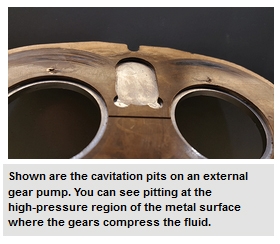
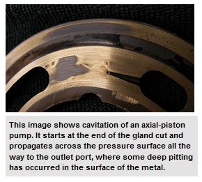
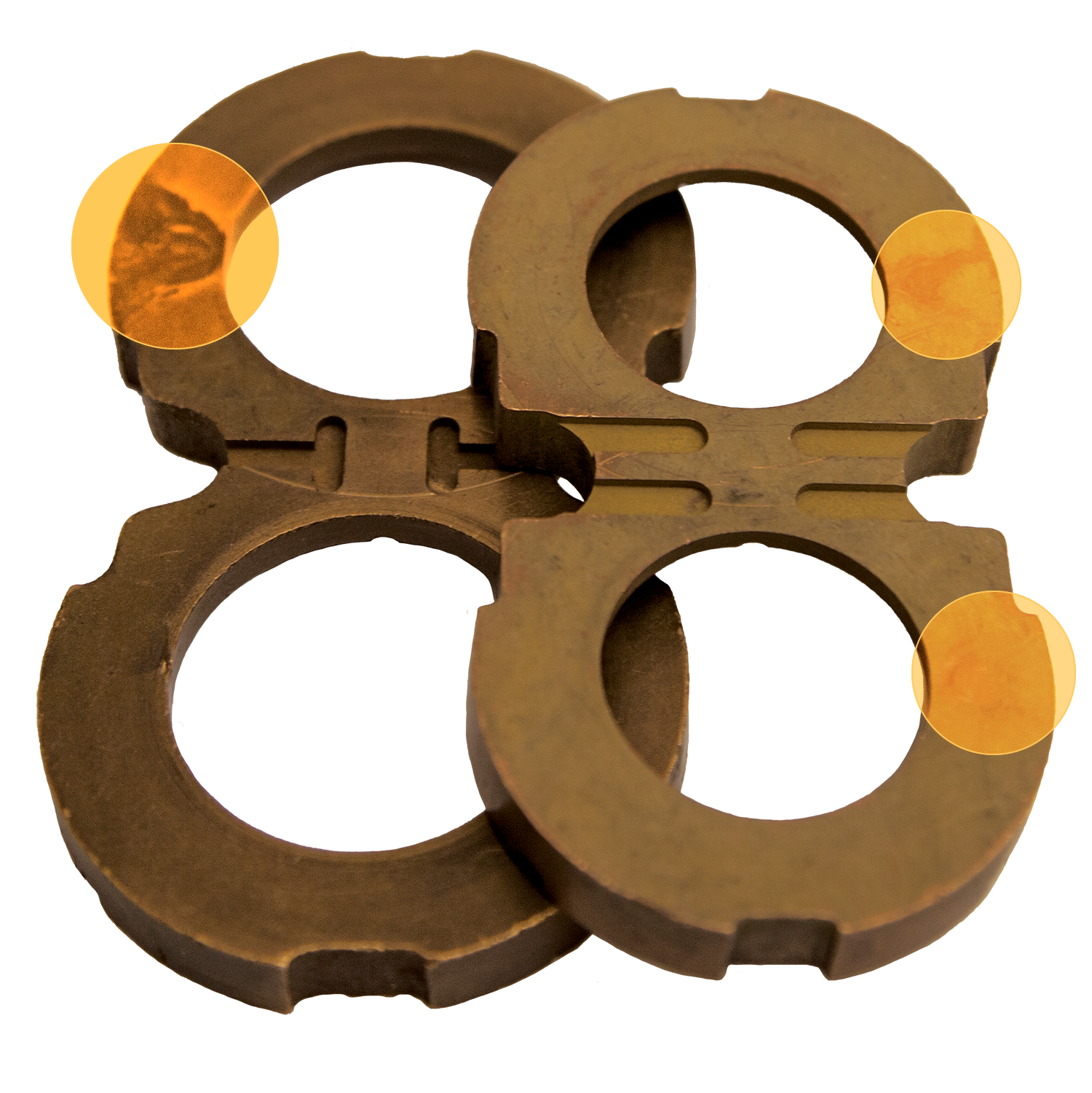
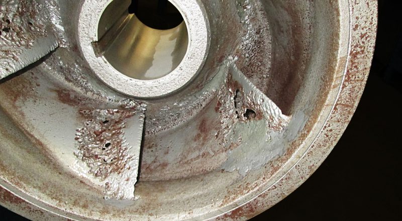
Material failure. The sudden destructive forces of the collapsing bubbles are powerful enough to cause pitting on the pump body or gear. Cavitation pitting has a distinctly different appearance than corrosion or erosion.
Many methods have been used to combat cavitation. In large centrifugal pumps or valves, admitting air into the inlet provides a cushion for the collapsing bubbles and also reduces the noise and pitting caused by cavitation.
Installing an accumulator (a mechanical device that stores the energy of fluid under pressure) close to the inlet port of a piston pump will reduce the effective inlet tubing length, pressurize the inlet, and absorb excess energy (see Fig. 2).
Pitting can be reduced by changing the hardness of the pumping element material or by applying a protective coating; however, these are not long-term solutions to the problem because pitting will attack areas with nicks, scratches, flaws, or sharp corners.
To reduce the undesirable characteristics of cavitation requires an understanding of the interrelationships of system, pump, and liquid. The following techniques have been used to reduce cavitation, but success is dependent upon the application:
Provide adequate pressure to the inlet of the pump, especially in applications with warm or hot liquids, thick viscous fluids, evacuated systems, or when the pumped liquid is volatile. Inlet pressures can be increased by raising the reservoir, lowering the pump, reducing the friction losses of the inlet tubing, or cooling the liquid.
Solutions to cavitation problems are not simple. System changes in gear pump applications can be expensive, time consuming, or both. In the early stages of a project, the design team, consisting of the user and the pump designer, must combine their knowledge to reduce the likelihood of cavitation within a fluid system.

As pressures and temperatures fluctuate in a hydraulic system, the fluid will absorb gas or release dissolved gases to main this equilibrium. The release process is gaseous cavitation.
It’s important to understand that the bubbles are not a result of a phase change. Unlike vaporous cavitation, there is no final gas-to-liquid phase change. Thus, the material erosion caused when vapor bubbles violently collapse does not occur with gaseous cavitation.
It is important to understand that aeration and cavitation are not the same thing, but a relationship exists between them. Aeration simply refers to a presence of air in a liquid.
Vaporous cavitation is not related to aeration. Again, the bubbles created by this process are simply a liquid-to-vapor phase change—they do not contain any air.
If free air in the crankcase becomes bound to the oil (by agitation, for example), the resulting entrained air bubbles may be unable to escape before reaching the suction inlet of the oil pump. These air bubbles will diffuse into the oil due to the higher pressure on the discharge outlet. As the pressure drops through the oil galleries and return to the sump, the air bubbles will re-emerge through the process of gaseous cavitation.

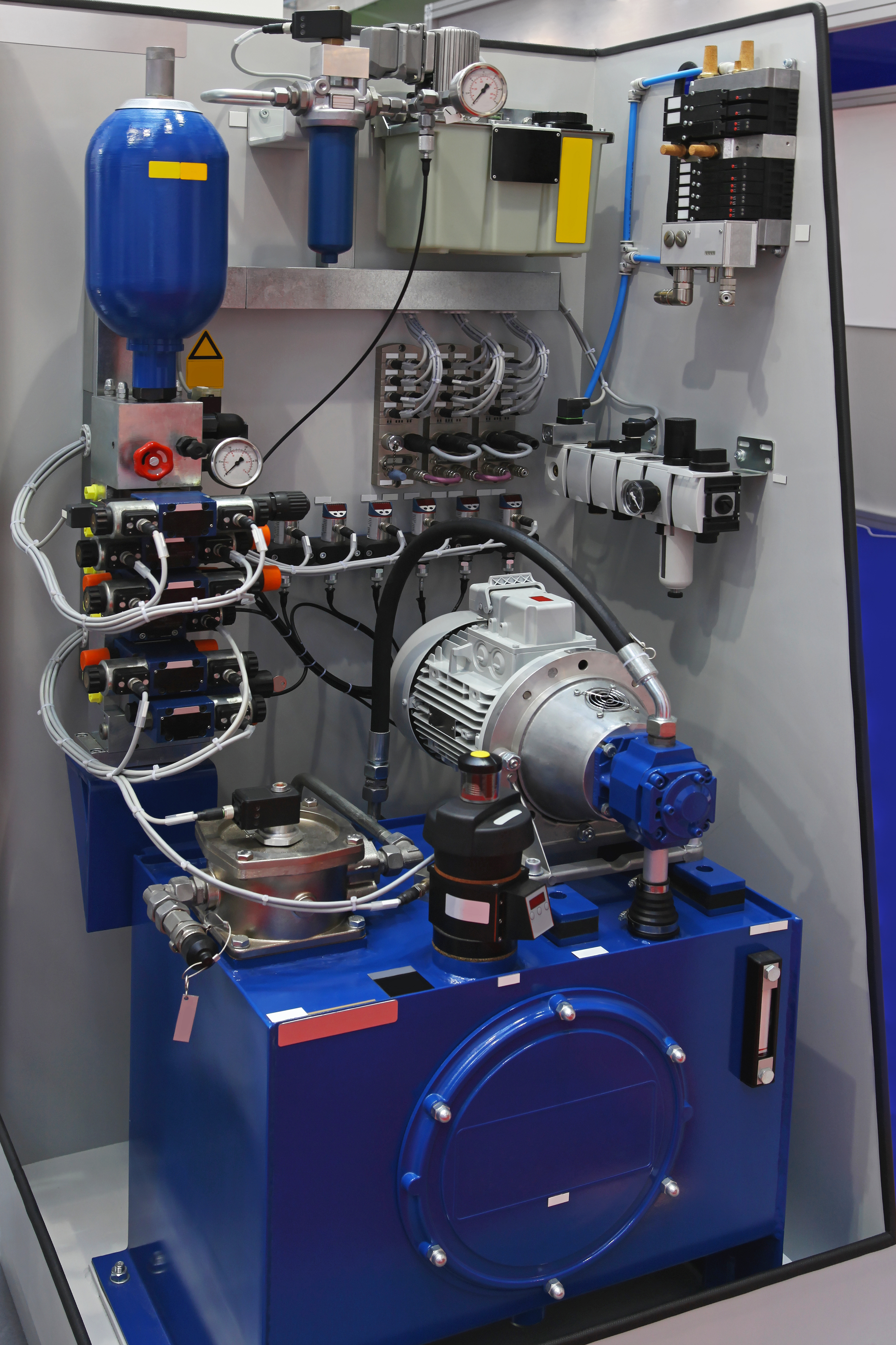
The pump is the most expensive and critical component in any hydraulic system—it works by first creating a vacuum at the pump inlet, which generates atmospheric pressure. Liquid from the reservoir tank is then propelled through the inlet line to the pump, past a hydraulic filter or strainer, and into the hydraulic system. On a macro-level, the mechanical energy of the pump’s gears is transferred through fluid “flow” and used to power the attached hydraulic machinery.
Although hydraulic systems can be used in many everyday objects, they’re usually best suited for products that require high-power density or systems with changing load requirements. This simple yet elegant design offers exceptional consistency and speed compared to other driving mechanisms. Hydraulic systems are widely used across industries because they are reliable, easy to maintain, long-lasting, and safe. But despite their many advantages, hydraulic systems still require some degree of maintenance. The following guide explains what can make a hydraulic pump fail, as well as tips for extending its useful lifespan as much as possible.
Fluid contamination is the leading cause of pump failure and usually happens when particulates circulate through the system via a breather valve or cylinder rod, or as a result of repairs, welding slag, sealant, or refilling. Once contaminants enter the system, they can degrade parts, create buildup, change the fluid’s physical and chemical properties, corrode equipment, and lower the system’s overall efficiency.
Hydraulic pumps are designed to work within a specific pressure range. If pressures exceed the pump’s rating, it will likely overburden the pump, cause damage, and eventually halt operations completely. If the pressure changes are extreme, it could even cause an explosion.
Joints and shafts must be completely sealed for the hydraulic pump to work properly. If air gets trapped inside the system, bubbles can cause pressure and temperature fluctuations, which eventually will cause the pump to break down. Usually the first sign there’s air in the pump is a high-pitched whine.
Cavitation occurs when the pump speed is inconsistent, creating air bubbles that rapidly form and then collapse. When this happens, the pump won’t completely fill with fluid, which destabilizes pressure in the system and produces the same type of high-pitched squeal as pump aeration. A blocked pipe, clogged filter, or poor system design can all cause cavitation.
Hydraulic systems need high-quality cooling and lubrication oil with the right mineral content and viscosity. Purity is particularly important for high-pressure systems that operate with larger loads.
The best way to prevent hydraulic pump failure is to inspect and maintain your hydraulic system. Hydraulic filters and strainers will help you avoid fluid contamination, which in turn will stabilize the temperature and pressure inside the system. Filters remove particulates that are smaller than 50 microns, and strainers work tangentially to remove contaminants larger than 50 microns. Various options are available for both filters and strainers using different ratings, mesh sizes, and materials.
After they’re installed, filters and strainers need to be routinely checked and cleaned. Operators should familiarize themselves with their hydraulic system to identify any aberrant conditions as soon as possible, if problems should arise. If you maintain your hydraulic system, it will work more efficiently, necessitate fewer repairs, require less downtime, and last as long as possible.
With over 60 years of experience manufacturing high-quality suction filters, suction strainers, gauges, and diffusers for hydraulic systems, the experts at DOMS Incorporated have the expertise to keep your operation in peak condition. We’ve worked closely with organizations from many industries, including construction, forestry, mining, energy development, industrial manufacturing, aircraft equipment manufacturing, plant processing, and more.

Oil viscosity is greatly impacted by the temperature of the oil, with low temperatures causing increases in viscosity which makes it difficult for the oil to reach the pump. Generally, it is best to avoid starting hydraulic systems with oil colder than 40°F (4°C) or putting under load with oil colder than70°F (21°C).
Reservoirs do not always have heaters, especially in the South. Those that do possess available heaters are usually disconnected. Although the damage may not be instantaneous, a pump regularly started using cold oil will eventually fail prematurely.
Investing in a hydraulic oil of high viscosity index base oils with low pour points for wide temperature range applicability, like CITGO’s Mystik® JT-9™ LeakShield® AW Hydraulic Oil, can help prevent such cavitation.
Once a year at minimum, the suction strainer needs to be removed from the reservoir and cleaned. It is prudent to keep in mind that strainers may become blocked for a variety of reasons. If there seems to be a malfunction with a pump—before taking any drastic action, like making replacements—check to ensure nothing has obstructed the suction line.
Every pump has a maximum drive speed. High speeds require higher volumes of oil at the suction ports. If an electric motor is driving the hydraulic pump at speeds over the pump’s rating, you might be gearing up for a crash course in cavitation.
Adequate oil volume is unable to flow into the suction cavity in the pump due to the port’s size, causing the pump to cavitate. Maximum drive speeds can range from as low as 1,200 revolutions per minute (RPM) to as high as 3,600 RPM — so always check drive speed when replacing a pump with that of a different brand or model. Cavitates tend to be rare but being mindful of your pumps’ maximum drive speeds can prevent costly mishaps, such as leaks and other cavitation-induced damage altogether.
Hydraulic pumps are at the core of many essential factory operations. Unfortunately, there are numerous pitfalls to plan for, mitigate, and overcome to keep them running. Keeping up on routine maintenance is important, but the best way factory techs can avail themselves of costly, frustrating breakdowns is to understand the various catalysts for hydraulic pump failure.
The simplest way to identify the cause of pump failure is to thoroughly inspect and dissect the aftermath of the problem. In most cases, the cause of failure will be evident by the nature of the catalyst(s). Here are eight of the most common problems, some of their defining features, and how they ultimately come to fruition.
1. Fluid contamination is one of the biggest causes of hydraulic pump damage and involves debris mixing with the liquid. This debris causes friction, leading to extenuated wear on the pump itself. The result is inefficiency, culminating in malfunction.
2. Fluid viscosity issues occur when the hydraulic fluid within a pump breaks down over time. Viscosity that’s too high leads to cavitation (another catalyst for damage). Subsequently, if a tech changes and replaces fluid with a viscosity that’s too low, heat and friction become concerns.
3. Over-pressurization occurs because of excessive load on the pump itself, resulting in red-line operation that’s both unsafe and damaging. Hydraulic pumps operating under high duress for extended periods of time will likely experience component wear and premature failure, usually in spectacular fashion.
4. Excess heat can be a product of poor fluid viscosity or environmental factors. This issue is rarely a singular catalyst for pump breakdown, but it exacerbates other factors or masks other issues, such as fluid contamination.
5. Implosion invariably results in extreme failure for hydraulic pumps and is a major safety hazard. Implosion occurs when air bubbles within a hydraulic pump collapse, causing an overload of pressure to the pump that generates an intense shock.
6. Aeration occurs when hydraulic fluid traps air bubbles. The pump subjects the bubbles to pressure, causing high heat and over-pressurization when the bubbles collapse. Aeration at extreme levels leads to implosion.
7. Pump aeration pertains to air not in the hydraulic fluid, but air introduced through unsealed joints or shafts. This air quickly causes pressure instability affecting crucial parts of the pump. This can quickly lead to breakdowns — generally marked by a whine or other high-pitched sound.
8. Cavitation is a symptom of uncontrolled pump speeds, which fail to allow hydraulic fluid to completely fill the pump. It results in destabilized pressure, heat, and excess wear. Cavitation is often marked by the same type of whine or squeal as pump aeration.
Because the factors causing each of these problems differ in nature, it’s best to fully evaluate a damaged hydraulic pump to determine if more than one issue is responsible.
Maintenance is the best approach for ensuring safe, efficient hydraulic pump function. But routine service is just the start. Identifying common issues plaguing your hydraulic pumps will lead to a better quality of targeted maintenance — for example, if you pinpoint a heat issue related to viscosity, that issue may be resolved by opting for a different fluid weight.
Every piece of information learned about your pumps can translate into better care, leading to longer uptimes, fewer issues, and fundamentally better maintenance.
Having trouble identifying the catalysts for your hydraulic pump’s issues? Let the professionals at Global Electronic Services take a look! Contact us for all your industrial electronic, servo motor, AC and DC motor, hydraulic, and pneumatic needs — and don’t forget to like and follow us on Facebook!
The damage due to cavitation can range from minor pitting to a total breach of the inside of the pump. Some people describe the damage as looking like Swiss cheese or as if "iron worms" have attacked it. As evidenced by the pictures, severe cavitation destroys the parts it contacts.
Cavitation damage can also reduce performance. Additionally, air pockets in the impeller can cause considerable hydraulic imbalance and resulting vibration. As the impeller is eroded, the uneven wear may cause further imbalance and vibration.
While Gorman-Rupp pumps are engineered to handle the deflection and loads created by cavitation, prolonged operation in this condition could eventually lead to bearing and/or shaft failure.
It is important to properly design the pumping system. (Contact distributor for calculating NPSH to avoid suction cavitation. Always calculate the total dynamic head to be within the operating range of the pump.) Correcting cavitation can be difficult if not impossible to do in an existing system.
To correct discharge cavitation (operating on the far left side of the curve) may require reducing the head or increasing the flow of the pump. Changing to a higher or lower speed may help in some cases, but a system head curve must be plotted to know the correct solution before corrective action is taken. The pump must be brought back inside its operating range.
Suction cavitation is caused by an NPSH problem. A vacuum gauge will indicate a high vacuum, not the source of that high vacuum. The cause of the high vacuum needs to be identified.
A plugged suction line should always be cleaned, not blown back to the liquid source. It will just come back to plug the line again. If the suction lift is too high the pump should be moved closer to the liquid or the liquid moved closer to the pump by raising the sump level. Suction lines that are too long or too small need to be shortened and/or enlarged.

The effects of cavitation are usually pretty easy to identify -- it causes a metal surface to have a pitted, crater-like appearance. What happens when cavitation takes place, and how it actually causes damage to normally resistant metals, isn’t quite as well known. In this Shop Talk Blog post, we’ll be talking about what causes cavitation and why it can result in so much damage.
There are three basic stages to cavitation: nucleation, bubble formation and growth, and bubble collapse. Note that damage doesn’t occur until the third stage -- collapse -- is reached.
Nucleation is actually a phase change, from liquid to vapor, that occurs due to a pressure drop. Now, in order to this phase change to occur, nucleation sites must be present. What is a nucleation site, you ask? Nucleation sites promote the occurrence of the phase changes, and include …
The critical pressure of most hydraulic systems is close to the equilibrium vapor pressure at the operating temperature of the hydraulic fluid, which means it is very easy for the fluid to become a vapor. As liquid flashes into vapor, the result is bubbles that are filled with a mixture of air and oil vapor. The result is a wide assortment of bubbles that begin to expand in size.
The bubbles are carried away from the nucleation site by the flow of hydraulic fluid. They travel to a region of higher pressure. Then, as the bubble expands, the pressure immediately around the bubble begins to increase. As that pressure goes up, it begins to deform the bubble into a kidney shape.
Cavitation is, to some degree, inevitable. However, one of the secrets to minimizing cavitation lies in keeping your hydraulic fluid as clean as possible, including free from air bubbles. The cleaner your hydraulic fluid, the less likely you will be to have nucleation sites that lead to cavitation.
is your partner in providing new or remanufactured final drive hydraulic motors from a single mini-excavator to a fleet of heavy equipment. Call today so we can find the right final drive or hydraulic component for you, or check out our online store to.
The transmission of medium is the premise of stable operation of the power supply system, which is achieved by the pump. A high-speed centrifugal pump has the characteristics of small volume and high head, which is often used for the transportation of the condensate in the system. The structure of a high-speed centrifugal pump, as shown in Figure 2, is mainly constructed by the motor, gearbox, and pump. The working principle of high-speed centrifugal pumps is similar to that of the ordinary centrifugal pump, but it obtains a high speed through the gearbox (Anmin Zhou, 2021).
High head and high speed are the characteristics of a high-speed pump. However, its defects cannot be ignored. It is prone to cavitation, and the excitation problem is more serious (Berten, 2009; Huimin Li, 2019). At the same time, the inefficient problem will also have a great impact on the operation of the pump (Zuchao Zhu, 2007; Kraeva, 2010). In addition, the structural design also affects the performance of the pump. Thus, researchers have conducted in-depth research on the hydraulic design and structural improvement of high-speed centrifugal pumps. In this work, a comprehensive review concerning high-speed centrifugal pumps is discussed. Hydraulic Design of High-Speed Centrifugal Pumps elaborates on the hydraulic design of the pump, which includes the research on cavitation, pressure pulsation, and inefficient problem. Structural Design of High-Speed Centrifugal Pump describes the current state of the pump’s structural design. Vibration Monitoring System describes the pump fault diagnosis, and conclusions are presented in Conclusion.
The hydraulic problem is an important consideration in the design and operation of high-speed centrifugal pumps, which seriously restricts the development of pumps. It is closely related to the flow phenomena. Some feasible schemes are put forward by analyzing these phenomena.
Cavitation is widely seen in high-speed centrifugal pumps. It will be generated when the absolute pressure of the liquid is lower than the vaporization pressure. The phenomenon will be different with different fluid media when cavitation occurs, which means that the impact on the pump is also different (Songsheng Deng, 2019). Generally, a low-pressure area appears when the backflow vortex occurs at the pump inlet, and the velocity is high and fluctuates greatly. As to the mechanism of the backflow, Stepanoff (J, 1947) pointed out that the inertial force of the liquid increases the circular velocity of the liquid around the blade when the flow rate decreases to near zero. This eliminates the energy gradient necessary to maintain the flow, resulting in backflow. Fraser (Warren, 1981) held that the pressure gradient at some points is reversed when the dynamic head exceeds the centrifugal head, which may cause backflow. It is found that the backflow vortex in the inlet section is caused by the liquid flow near the outer edge of the blades. For backflow, Shuai Hu (2017) found that the backflow vortex is mainly related to the flow rate under the condition of low flow rate. Zhao J (2014) showed that there are four types of vortices in the impeller channel, as shown in Figure 3. It is clear that type C occupies the largest space, causing the main flow problem.
Cavitation will have a great impact on the head. The head would drop precipitously when the cavitation coefficient decreases to a certain value (Xu Luo, 2018).
At present, the most widely used solution to the cavitation problem is to add an inducer in front of the impeller. Debarpan Paul (2020) pointed out that the inducer is the most effective at the operating range of the pump and tends to lose its function under off-designed conditions. The type, structure, head, and installation position of the inducer all affect the anti-cavitation ability of the pump.
The anti-cavitation ability can be improved by selecting a reasonable type of the inducer type. The velocity pre-spinning at the exit of the splitter blade inducer weakens the backflow, but flow blockage occurred in the splitter blade inducer with the flow rate increase. Xilong Huang (2020) calculated the cavitation number of different inducers under different flow rates. It can be seen from Figure 4 that the splitter blade inducer is suitable for small flow rates, and the variable pitch inducer is better for large flow rates.
In terms of the structure of the inducer, Xiaorui Cheng (2020) proposed that the change of the inducer inclination angle has a great influence on the anti-cavitation ability. It is found that the volume fraction of the gas phase in the inducer is the minimum when θ = 2°. The outlet pitch of the inducer has a significant effect on the cavitation. Guohong Wu (2016) pointed out that increasing the outlet pitch of the inducer can decrease the circumferential velocity of the inducer outlet, and the fluid obtains more pressure energy. At the same time, it can reduce the impeller axial clearance of the low-pressure zone. The anti-cavitation ability of the inducer can be improved by changing the surface of the inducer blade. Huimin Li (2019) cut slots on the inducer and divided the large cavitation of the inducer into several small cavitations, which improves the anti-cavitation ability of the inducer. For the splitter blade inducer, Xiaomei Guo (2012) pointed out that the position of the short blade had a significant effect on cavitation. The optimum position of the short blade in the inducer is L= 0.45 D. For the position of the inducer, the relative angle of the inducer and impeller has a great influence on the efficiency and cavitation capacity. The gas phase ratio between the inducer and impeller varies significantly with the circumferential angle (Baofeng Yang, 2019). The inducer will produce a head. On the basis that no cavitation occurs in the impeller, the higher the head of the inducer, the greater is the inlet pre-spinning of the impeller, and the worse is the cavitation resistance of the impeller (Huimin Li, 2020).
As the core structure of the pump, the internal flow state of the impeller directly affects the performance of the pump. The anti-cavitation ability can be enhanced by the design of the impeller.
The axial clearance of the blade has a significant effect on the cavitation. Lihong Zhang (2016) found that the low-pressure area at the blade’s back disappears with the increase in axial clearance, which enhances the anti-cavitation ability. The type of blade also affects the cavitation of the pump. The impeller blades are divided into two types: split blades and full blades. At a low flow rate, the blockage of the passage will decrease the inner pressure of the impeller. Jianping Yuan (2014) found that cavitation occurs in all passages of the 4 + 4 split blade pump, and part of the cavitation is serious, while the cavitation has not appeared in the full blades. The anti-cavitation ability can be improved by adding a balance hole on the impeller. The air bubble accumulates in the balance hole, which is then sheared away by the high-pressure fluid at the outlet of the impeller to improve the anti-cavitation ability. Hao Gao (2020) obtained the bubble distribution in the impeller by simulation, as shown in Figure 5. It can be seen that the balance hole can change the distribution of gas in the impeller directly.
The specific area of the balance hole is an important factor that affects the anti-cavitation ability of the pump. The larger the area of the balance hole, the larger is the leakage of the balance hole, and the vortex is induced at the inlet of the centrifugal impeller. Cheng (Xiaorui Cheng, 2020; Xiaorui Cheng, 2020) designed balance holes with different specific areas in pumps and analyzed the flow field. The simulated streamlines in Figure 6 show that flow in the balance hole is smooth when the specific area of the balance hole K = 0.5 and K = 1.
The second problem is hydraulic excitation. The excitation force is affected by the backflow and vortex. The research on the backflow and vortex has been provided in Cavitation. In addition, cavitation also has a great impact on it. Yeqiang Li (2017) simulated the distribution of the root-mean-square, as shown in Figure 7. Through comparison, it was found that the interaction becomes stronger in amplitude when cavitation occurs.
FIGURE 7. Prms on PS and SS of the blade (Yeqiang Li, 2017). (A) PS at non-cavitation. (B) PS at critical cavitation. (C) SS at non-cavitation. (D) SS at critical cavitation.
Xiaomei Guo (2011) simulated nine different schemes of the orifice plate design by the orthogonal method. It is concluded that the diameter of the orifice plate is the main factor affecting backflow, the thickness of the orifice plate is the second, and the distance between the orifice plate and the leading edge of the inducer is the third. Wenwu Song (2017) installed different kinds of orifice plates in the inlet section of the pump. It can be seen from Figure 8 that the backflow vortices are reduced after the orifice plate is installed, and the number of vortices in the C-type orifice plate is less.
In order to study the influence of the diameter of the c-type orifice plate, Chengfan Shi (2019) installed different diameters of the c-type orifice plate in the pump. It can be seen from Figure 9 that there is no axial backflow when the aperture is 1.0 and 0.8 R.
The structure of the impeller has a great influence on the pump. The inlet shape of the blade can change the flow condition and outlet velocity in the impeller. Qiang Li (2019) found that the highest amplitude of pressure pulsation is at the tongue. Also, it is pointed out that the vibration is caused by the interaction between the volute and the tongue. The pressure pulsation is affected by the splitter blades. Jun Liu (2013) designed three types of splitter blades and observed the flow field. From the results, the cross-section static pressure displays better uniformity in the impeller with splitter blades. Yuan Ye (2019) replaced the original impellers with two new types of impellers with splitter blades. The result shows that the pulsating pressure of the original scheme (Scheme 1) is obviously higher than the others.
The guide vane is located between the impeller outlet and the volute. It is found that the guide vanes can change the interference between the impeller and the volute. Therefore, hydraulic excitation can be reduced by guide vanes’ design (Xiuxin Yang, 2017).
The vortex in the guide vane channel is related to the relative position between the impeller and the guide vane. From Baofeng Yang’s (2019) study, the


 8613371530291