
what causes hydraulic pump cavitation pricelist

Hydraulic pumps are used in various industries to pump liquid, fluid, and gas. Although this equipment features robust construction, it may fail at times due to various issues. Cavitation is one of the serious issues faced by this equipment. Like all other technical issues, right planning as well as troubleshooting will help avoid this issue to a large extent. What is pump cavitation and how to troubleshoot these it?
It is seen that many times, Strong cavitation that occurs at the impeller inlet may lead to pump failure. Pump cavitation usually affects centrifugal pumps, which may experience several working troubles. At times, submersible pumps may also be affected by pump cavitation.
Non-inertial Cavitation: This type of cavitation is initiated when a bubble in a fluid undergoes shape alterations due to an acoustic field or some other type of energy input.
Suction Cavitation: This cavitation is brought by high vacuum or low-pressure conditions that may affect the flow. These conditions will reduce the flow, and bubbles will be formed near the impeller eye. As these bubbles move towards the pump’s discharge end, they are compressed into liquid, and they will implode against the edge of the impeller.
Discharge Cavitation: Here, cavitation occurs when the pump’s discharge pressure becomes abnormally high, which in turn affects its efficiency. High discharge pressure will alter the flow of fluid, which leads to its recirculation inside the pump. The liquid will get stuck in a pattern between the housing, as well as the impeller, thereby creating a vacuum. This vacuum creates air bubbles, which will collapse and damage the impeller.
Sound: The pump affected by cavitation will produce a marble, rock, or gravel type of sound when in motion. The sound will begin as a small disturbance and its intensity will increase as the material slowly chips away from the surface of the pump.
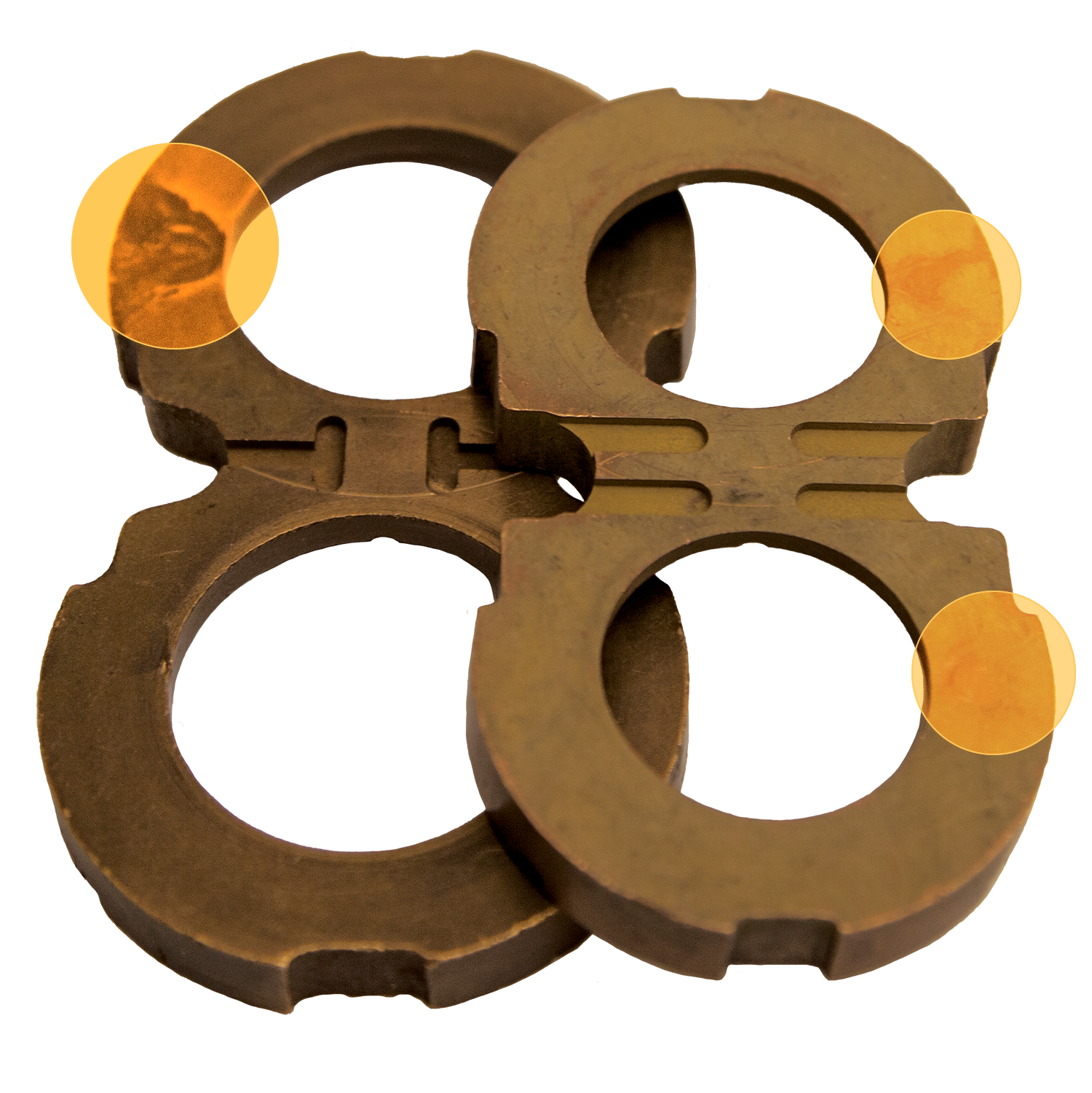
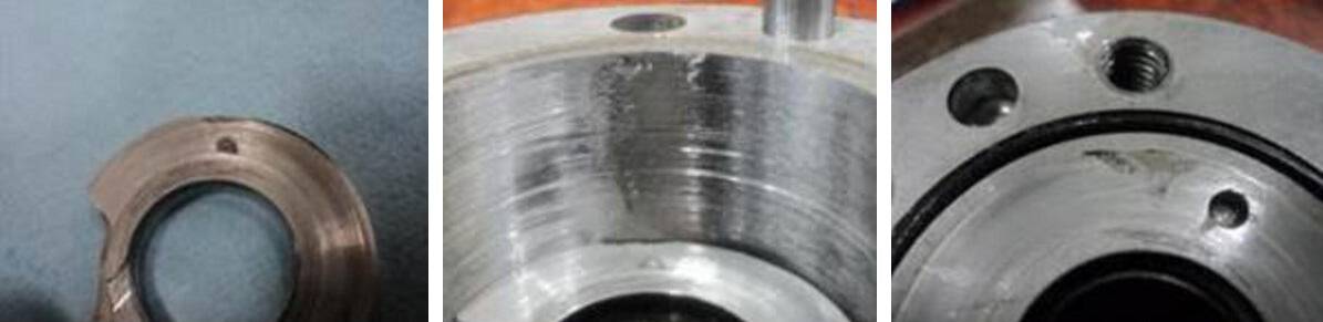
Metallic Debris: If during the maintenance, you find metallic debris on the filter of the hydraulic pump then it may be a symptom of cavitation. One of the easiest ways to confirm it is to check the filter. If any debris is found, you should clean the entire system, and thoroughly inspect the pump.
Damage: This is one of the most obvious symptoms of cavitation. If you already know that the pump is damaged, you need to remove its filter, open, and inspect it thoroughly. If you find a lot of metal inside the filter, then flush the entire system, and check for damages in other parts, too.
If you notice any of the above-discussed symptoms, the next step would be to identify the causes, and rectify the changes in industrial pumps, otherwise, it may affect other components, too.
Avoid using suction strainers: These are designed to inhibit the ingestion of grime and dirt. However, these strainers do not succeed in their purpose, because they are not designed to entrap large particles. These large particles may get deposited in the flow path, thereby affecting the flow of fluid. The deposition also creates pressure, and produces bubbles, which may lead to cavitation.
Clean the reservoir: A dirty reservoir is one of the most common causes of cavitation. Various types of small and large objects may block the suction tube, and create pressure, thereby causing cavitation.
Use properly sized components: This is one of the important factors of cavitation prevention. If the inlet plumbing is too large, there will be too much liquid flow, which may trigger cavitation. Hence, check with the pump manufacturer to ensure that properly sized components are being used in the pump.
In addition to these preventive steps, you must source hydraulic pumps from a trusted manufacturer or supplier. JM Industrial is one of the industry-leading provider of unused and used industrial process equipment from industry-leading brands. These pumps can be availed at cost-effective prices.
Pumps are designed to produce enough flow and pressure to move a liquid from one location to the next. Sounds simple enough, but the internal system of a pump is complex. When you combine the complexity of the pump system with the wide-ranging properties of various fluids, the surrounding environment, and other factors, cavitation can occur.
Pump cavitation is a potentially damaging problem in pumps that are not properly configured or being used for their intended application. Here, we’ll explore what causes cavitation in pumps, the signs to look for, and ways to prevent it from happening.
Pumps are designed to pump liquids but, when the combined flow rate and pressure are inadequate or not conducive to the type of liquid being pumped, pockets or cavities can form, resulting in cavitation.
Some describe pump cavitation as the creation and collapse of the air bubbles in a fluid. While they may appear to look like air, those bubbles are technically a cavity, gaseous vapor, or vacuum. While cavitation is possible in all pump types, it is more common in centrifugal pumps where the bubbles quickly develop around the impeller’s axis. When the bubbles pass from the middle of the impeller to the outer edges, the centrifugal force creates higher pressure, causing those bubbles to quickly collapse or implode with great force.
Pump cavitation is the rapid succession and released energy of the implosions of gaseous cavities which cause an intense rattling sensation that can damage a pump.
Various conditions can make a pump more prone to cavitation. A clogged filter or strainer, for example, can easily restrict flow and lead to pump cavitation. Similarly, a restricted or flimsy inlet hose might collapse and cause issues. Fluid viscosity is a major contributor, too, especially when combined with the wrong hose. Imagine drinking a milkshake through a thin straw: the combination of the thick viscosity, pressure, and weak structure of the straw causes it to collapse and restricts the flow. Or consider if that straw has a pinhole in it; the leak would also affect flow and pressure. Similar phenomena can occur in pump systems.
That said, the inlet supply hose can’t be too rigid either. If you use a solid metal hose or a system is plumbed with hard PVC or copper piping, it could cause water hammering. Finding the right combination of dampening with a strong yet soft inlet hose or flexible PVC is ideal. Here at Pumptec, we use pulse hoses with metal springs inside them to add strength and rigidity. They’re less likely to collapse yet still offer the right level of flexibility.
The position of the reservoir tank also makes a difference. If the tank is positioned below the pump, the pump will need to decrease pressure to draw the fluid vertically through the inlet piping. The longer the inlet hose and the farther the vertical distance between the tank and the pump, the greater the chance of creating a vacuum and cavitation.
Heated liquids are a major contributor to cavitation, too, especially as the hot fluid approaches the boiling point and creates additional vapor pressure. In this instance, the liquid needs to be fed/pushed through a pump rather than drawn/pulled through it. The easiest way to achieve this is to have the tank containing the heated fluid elevated above the pump so that it is gravity fed into the pump system.
In all these instances, the flow is being disrupted or poorly executed, causing the discharge pressure to fall. The pump is basically being starved of fluid, resulting in cavitation.
Obvious signs of pump cavitation are excessive noise and vibration. The implosions and released energy within the system produce a loud growling sound, or it may sound and feel like gravel is circulating through the system.
Cavitation can damage seals, O-rings, and bearings, resulting in leaks and loss of pressure. On a centrifugal pump, the constant force of the implosions can erode the impeller and pump housing. Because of the added strain, the pump will also consume more power than it should.
On a positive displacement plunger pump, cavitation can erode seals and the metal around the poppet and seat on the check valves. If the pump body is made of anodized aluminum, which appears as a black coating, the black anodization will wear away upstream from the outlet check valve. In extreme cases, wear will occur outside of the main seal. If that happens, the pump will start sucking air, and bubbles — sometimes called washout — will form on the outlet.
Many of these issues can be prevented with proper maintenance and by selecting a pump that is designed for the intended use, accommodates the viscosity of the fluid being pumped, and has the proper configuration.
Some people think they just need to increase the size of the inlet hose. While it’s true that a hose that’s too small could cause cavitation, having a hose that’s too large could cause priming problems.
Centrifugal pumps have such high flow rates that it’s difficult to control their output, plus they have a lot of back pressure downstream that affects the amount of flow. Because of their lower flow rates, plunger pumps typically have fewer cavitation issues.
All in all, the pump pressure must be maintained above the liquid"s vapor pressure to avoid cavitation. In the end, the best tip for reducing cavitation is to work with a pump manufacturer to determine the proper use and placement for your application.
Contact the pump experts at Pumptec to discuss your pump challenges and how to overcome them with a solution that’s customized to your application. Get a head start by checking out our

The second leading cause of hydraulic pump failure, behind contamination, is cavitation. Cavitation is a condition that can also potentially damage or compromise your hydraulic system. For this reason, understanding cavitation, its symptoms, and methods of prevention are critical to the efficiency and overall health of not just your hydraulic pump, but your hydraulic system as a whole.
The product of excessive vacuum conditions created at the hydraulic pump’s inlet (supply side), cavitation is the formation, and collapse of vapors within a hydraulic pump. High vacuum creates vapor bubbles within the oil, which are carried to the discharge (pressure) side. These bubbles then collapse, thus cavitation.
This type of hydraulic pump failure is caused by poor plumbing, flow restrictions, or high oil viscosity; however, the leading cause of cavitation is poor plumbing. Poor plumbing is the result of incorrectly sized hose or fittings and or an indirect (not straight or vertical) path from the pump to the reservoir. Flow restrictions, for example, include buildup in the strainer or the use of an incorrect length of hose or a valve that is not fully open. Lastly, high oil viscosity—or oil that is too viscous—will not flow easily to the pump. Oil viscosity must be appropriate for the climate and application in which the hydraulic pump is being used.
The greatest damage caused by cavitation results from the excessive heat generated as the vapor bubbles collapse under the pressure at the pump outlet or discharge side. On the discharge side, these vapor bubbles collapse as the pressure causes the gases to return to a liquid state. The collapses of these bubbles result in violent implosions, drawing surrounding material, or debris, into the collapse. The temperature at the point of implosion can exceed 5,000° F. Keep in mind that in order for these implosions to happen, there must be high vacuum at the inlet and high pressure at the outlet.
Cavitation is usually recognized by sound. The pump will either produce a “whining” sound (more mild conditions) or a “rattling” sound (from intense implosions) that can sound like marbles in a can. If you’re hearing either of these sounds, you first need to determine the source. Just because you hear one of these two sounds doesn’t guarantee that your hydraulic pump is the culprit.
To isolate the pump from the power take-off (PTO) to confirm the source, remove the bolts that connect the two components and detach the pump from the PTO. Next, run the PTO with no pump and see if the sound is still present. If not, it is safe to assume your hydraulic pump is the problem.
Another sign you may be experiencing cavitation is physical evidence. As part of your general maintenance, you should be inspecting and replacing the hydraulic oil filter"s elements at regular intervals based on the duty cycle of the application and how often it is used. If at any time during the inspection and replacement of these elements you find metallic debris, it could be a sign that you’re experiencing cavitation in the pump.
The easiest way to determine the health of your complete hydraulic circuit is to check the filter. Every system should have a hydraulic oil filter somewhere in-line. Return line filters should be plumbed in the, you guessed it, return line from the actuator back to tank—as close to the tank as possible. As mentioned earlier, this filter will have elements that should be replaced at regular intervals. If you find metallic debris, your pump could be experiencing cavitation. You’ll then need to flush the entire system and remove the pump for inspection.
Conversely, if you’ve already determined the pump to be damaged, you should remove the filter element, cut it open, and inspect it. If you find a lot of metal, you’ll need to flush the entire system and keep an eye on the other components that may be compromised as a result.
Once cavitation has been detected within the hydraulic pump, you’ll need to determine the exact cause of cavitation. If you don’t, cavitation can result in pump failure and compromise additional components—potentially costing you your system.
Since the pump is fed via gravity and atmospheric pressure, the path between the reservoir and the pump should be as vertical and straight as possible. This means that the pump should be located as close to the reservoir as is practical with no 90-degree fittings or unnecessary bends in the supply hose. Whenever possible, be sure to locate the reservoir above the pump and have the largest supply ports in the reservoir as well. And don"t forget, ensure the reservoir has a proper breather cap or is pressurized (3–5 PSI), either with an air system or pressure breather cap.
Be sure the supply line shut-off valve (if equipped) is fully open with no restrictions. This should be a “full-flow” ball valve with the same inside diameter (i.d.) as the supply hose. If feasible, locate a vacuum gauge that can be T’d into the supply line and plumb it at the pump inlet port. Activate the PTO and operate a hydraulic function while monitoring the gauge. If it reads >5 in. Hg, shut it off, and resume your inspection.
A hose with an inner bladder vulcanized to a heavy spiral is designed to withstand vacuum conditions as opposed to outward pressure. The layline will also denote the size of the hose (i.d.). You can use Muncie Power’s PPC-1 hydraulic hose calculator to determine the optimal diameter for your particular application based on operating flows.
Another consideration, in regards to the inlet plumbing, is laminar flow. To reduce noise and turbulence at the pump inlet, the length of the supply hose should be at least 10 times its diameter. This means that any type of shut-off valve or strainer at the reservoir should be at least 10 diameters from the pump inlet. A flared, flange-style fitting at the pump inlet can also reduce pump noise by at least 50 percent compared to a SAE, JIC, or NPT fitting.
Selecting the proper viscosity of hydraulic fluid for your climate and application is also critical. Oil that is too viscous will not flow as easily to the pump. Consult your local hydraulic oil supplier for help selecting the optimal fluid viscosity.
By maintaining a regular maintenance schedule, remaining vigilant for any signs or symptoms, and taking preventative measures, the good news is that you should be able to prevent cavitation and experience efficient operation for the duration of your pump’s lifespan.
Poor plumbing is the leading cause of cavitation and can be prevented by selecting a properly sized hose, choosing the appropriate fittings, ensuring the most direct, straight routing from the pump to the reservoir, etc.

Two leading causes why hydraulic pumps usually fail are: (1) contamination and (2) cavitation. In order to prevent any potential damage to your entire hydraulic system, it’s imperative to understand cavitation, the indications or symptoms from your system it is occurring, as well as the preventive measures.
How does cavitation happen exactly? It starts when vapor bubbles in the oil are created due to high vacuum. When these vapor bubbles are carried and collapsed on the pump outlet (discharge side), cavitation happens.
Make Sure Oil flow Paths are Straight – Hydraulic pumps are being supplied via atmospheric pressure and gravity, so it’s ideal to place the reservoir above it. Make sure that the path is as straight and vertical as possible. Keep an eye on bent or twisted supply hose.
Check Laminar Flow – If you’re hearing turbulence or noise in pump inlet, make sure that the supply hose length is the correct ratio to its diameter. A flange-style, flared fitting in the pump inlet can also help in eliminating pump noise.
Check Proper Viscosity – It"s important to choose the hydraulic fluid with appropriate viscosity for your application and climate. Consult with your supplier for professional help in choosing the optimal fluid viscosity.
With regular maintenance, keeping an eye on symptoms, and taking preventive measures, you’d be able to avoid cavitation and expect efficient operation from your hydraulic pumps.

It differs little if it is a pump on an engine, a hydraulic system, or any other application. Fact is, a broken pump can bring your entire operation to a standstill. Though pumps can fail due to age and use, the reality is that most are murdered, snatched from their prime with much life left in them. The culprit is cavitation, and it sends warning signs (excessive vibration, hammering, groaning, and whistling) but most are ignored.
Pump cavitation describes the formation of bubbles or cavities in the bulk fluid being moved that usually develops around a low-pressure area. This is the result of either an entrained gas in the liquid from the vapor pressure being exceeded or from a lack of flow. When the vapor bubbles collapse or implode, they strike at the speed of sound, creating the noise and vibration. This collision will erode the surfaces of the pump and impeller, and will attack the bearing, shaft alignment, and seal.
When you examine a failed pump, you will notice an appearance that resembles a sponge-like texture or missing material. Depending on the pump design and operating characteristics, the bearing may fall victim first, allowing excessive shaft movement and a collision of the impeller with the housing. Minor cavitation will result in decreased output or pressure. It is imperative that you are cognizant of the sound and pressure/flow characteristic of your pumps. Cavitation caught in the early stages will have minimal to no impact on pump life.
Suction side cavitation occurs when a pump is under low pressure or excessive vacuum. The pump is being starved of liquid and is not being fed enough flow. At that time, bubbles form at the eye of the impeller (where it connects to the shaft). As these bubbles move over to the discharge region, the fluid condition is altered and the bubbles are compressed into a liquid, causing them to implode against the face of the impeller. An impeller subjected to suction side cavitation will have pieces of material missing.
Discharge cavitation is the result of the discharge pressure being extremely high, so that it is difficult for the liquid to vacate the pump. It then circulates around the impeller and housing causing a very high vacuum at the wall and the formation of bubbles. Discharge cavitation allows the imploding bubbles to create intense shock waves, removing material from the housing and impeller. In extreme discharge cavitation cases, the impeller shaft may even break.
The most common cause is a flow restriction or running the pump at a speed that is out of its operating range. The flow issue can be either on the suction or pressure side, or a cumulative effect of both. Proper and timely maintenance of filters and screens goes a long way in preventing cavitation. Keep in mind that on a sprayer or other application with aged rubber hoses, they can be collapsing slightly and limiting suction performance and evoking cavitation.
Plumbing design such as pipe diameter and the amount of turns and the sharpness of them will potentially create either suction or discharge cavitation. You may have upgraded to a larger pump and now the factory piping cannot support it. No fluid likes to make turns; this will result in a flow restriction, both on the feed and discharge sides.
If a pump does fail, you need to take it apart and determine if it was the result of cavitation. On an engine, the coolant (water) pump seal can fail prematurely if the rpm is brought too high while the thermostat is closed. During that time, the coolant is being forced through a small bypass hose or passage. Excessive engine speed even under no load will cause the suction side of the pump to experience a very high vacuum and, over time, violate the pump seal and leak from the weep hole. On any engine, the rpm should be moderated when the coolant is below the temperature of the thermostat opening point.

An in-depth description of what cavitation is, how cavitation can occur in pumps, how to prevent pump cavitation, and the effects pump cavitation can have on your pump. Pump cavitation is very noticeable and can cause serious damage to your pump, so it"s important to be able to identify and diagnose cavitation whenever it occurs.
Cavitation is the formation of bubbles when the pressure in certain spots of a pump begins to reach the vapor pressure of the fluid inside. When the pressure inside the pump gets as low as or lower than the vapor pressure of the fluid, the fluid begins to evaporate, creating bubbles. These bubbles exist until they reach a higher pressure area.
Pump cavitation is generally found in the inlet of pumps or in narrow piping sections, which are the areas that will have the lowest pressure in the pump. This is most pronounced around the edges of any inlet in the pump. The bubbles formed by these low pressure areas quickly reach an area pressurized enough to turn them back into water. Due to the properties of water when pressurized, when the bubbles pop they emit a powerful pressure shock. The volume of bubbles and shocks creates a loud noise.
The reason cavitation can be damaging comes from how each bubble collapses. Rather than the pressure shock damaging the pump, a small stream of water is expelled from the center of the bubble, and is powerful enough to cause micro cracks in material. Over time, this effect builds up, so much so that the pump can be seriously damaged. This small stream of water, called a micro jet, is formed by the way the bubble explodes - or more precisely, implodes.
Each cavitation bubble implodes upon itself, with the leading edge pushing back towards the opposite end of the bubble. Essentially, when the two edges make contact, they open up a hole in the bubble, and the force of the two edges connecting drags water through the newly-formed hole and launches the micro jet of fluid directly out. The micro-cracks caused by this are not immediately serious, but over the course of several months to a few years, cavitation can seriously damage the pump.

Cavitation is a common mode of wear in hydraulic pumps and control valves. The damage to components more often than not results in severe losses of service life times and flow efficiencies. Understanding the causes behind this phenomenon is the first step in developing solutions to combat its harmful effects.
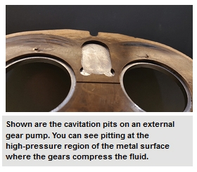
When the local static pressure in a fluid (inlet pressure) falls below the fluids vapour pressure (a characteristic property) at that particular temperature, vapour bubbles form in the fluid/hydraulic oil. Now, when we talk about bubbles, it is difficult to imagine that something so small can do incredible amounts of damage to hydraulic components. The vapour bubbles themselves pose no threat when floating around in the fluid. When the bubbles make it to the high pressure side of the pump/valve, however, they condense instantaneously and the bubbles collapse and produce hydraulic micro-jets which act similar to shockwaves. These micro-jets impinge on the metal surfaces, thereby destroying the material bonds (cavitation damage), and often result in (1) The creation of loud rolling noises (2) Vibration of the pump (3) The delivery of less flow and (4) Pitted erosion (as shown below).
The common causes of cavitation that allow the fluid to have a low static pressure can be grouped into three categories i.e. inlet inadequacies, fluid properties, and pump position.
Inlet inadequacies: These are often the case in systems when there is a restriction to the flow of the hydraulic fluid. Be sure to regularly look out for clogged strainers/filters, too many bends in the inlet line, and/or a collapsed inlet hose. Additionally, during the design and installation stage of your system, ensure the inlet pump lines are correctly sized and not too small.
Fluid properties:If your fluid is in a state that allows it to vaporise easily, the risk of cavitation is increased. This means that there is a presence of water particles and/or the hydraulic fluid is too viscous to be easily forced into the pump as a result of low temperature. Ensure that you use a good quality hydraulic oil, keep it isolated from external wet sources and, if necessary, heat it up before use as you would with warming up your rig’s engine.
Pump position: If your pump is too far away from the reservoir or too far above your reservoir you will have a low suction pressure allowing the formation of cavitation bubbles to occur. Make sure to use a pump with good filling characteristics or with a flooded suction. Alternatively, your design could incorporate a supercharged inlet.
Although cavitation can occur anywhere in a hydraulic system, it commonly occurs within the suction line of a pump. This will cause excessive noise in the pump – generally a high pitched “whining” sound. However, this excessive noise is only the tip of the iceberg! The real result of this phenomenon is severe pump damage and a decrease in pump life. I have personally seen many instances where a customer was replacing pumps frequently, thinking they were receiving defective pumps from their vendor. In reality, the pump failures were not due to poor pump quality – the failures were occurring because of cavitation.
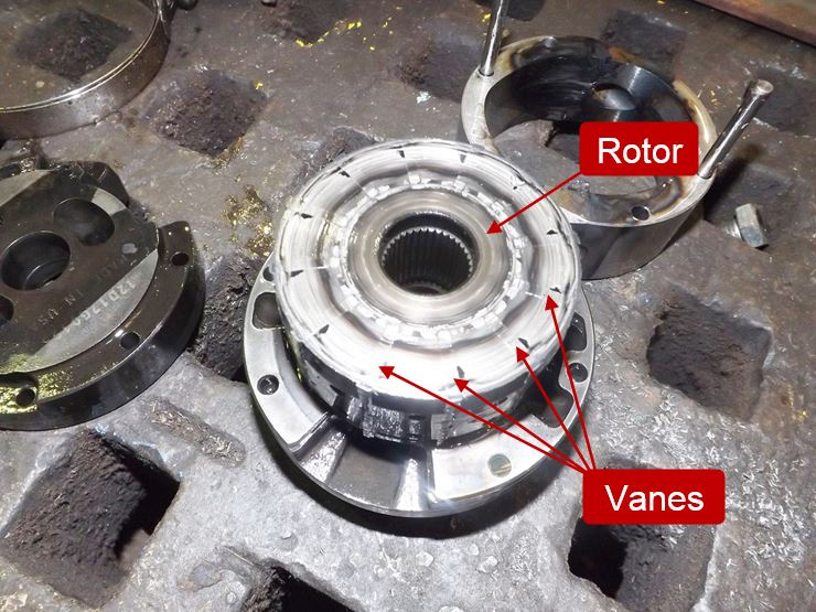
Simply put, cavitation is the formation of vapor cavities in the hydraulic oil. In hydraulic pumps, cavitation will occur any time the pump is attempting to deliver more oil than it receives into the suction (inlet) line. This is commonly referred to as “starvation” and results from a partial vacuum in the suction line. To fully illustrate what is happening when this occurs, we need to discuss vapor pressure. Vapor pressure is the pressure below which a liquid at a given temperature will become a gas, and this pressure varies significantly depending on the liquid. Generally, as the temperature of a liquid rises, the vapor pressure will proportionally increase. Likewise, as the temperature decreases, the vapor pressure will decrease. Most of us know that water will boil (turn to vapor) at 212°F (100°C) at 14.7 PSI (atmospheric pressure at sea level). In other words, the vapor pressure of water at 212°F is 14.7 PSI. If the pressure is reduced, the temperature at which the water boils will be reduced. If the temperature is lowered, the vapor pressure will decrease. In fact, water will boil at room temperature if the pressure is sufficiently reduced! The same principle applies to hydraulic oil, although the vapor pressure will be somewhat different than that of water. The vapor pressure of hydraulic oil is somewhere between 2 and 3 PSI at normal temperatures. In ideal conditions, the pressure in the suction line of the pump will be around 14.7 PSI at sea level. Of course, this pressure decreases with altitude, but sufficient pressure will normally be maintained in the suction line to prevent cavitation of the oil. However, if the pressure in the suction line of the pump is sufficiently reduced to the vapor pressure of the oil, vapor cavities will form. As the oil passes from the suction line to the outlet of the pump, the pressure will increase and the vapor cavities will implode violently. These extremely powerful implosions will cause erosion and premature failure of the pump components. In fact, a brand-new pump can be destroyed in a matter of minutes if the cavitation is severe enough. The picture below shows a rotor and cam ring from a vane pump that had failed due to severe cavitation.
In my 35-plus years of troubleshooting hydraulic components, this is the worst case of cavitation damage I have ever seen. In addition to the usual erosion of the parts, the vanes were actually fused to the rotor slots! Although this is an extreme example, it shows the potential damage to a pump due to cavitation. The good news is that cavitation is preventable and we will look at several conditions that can trigger this phenomenon.

Air that enters a hydraulic system can cause many problems that could subsequently lead to system failure. Here FPE Seals discusses how to spot these potential problems and why it is so important that air is bled from a system as soon as it is detected.
Essentially, hydraulic pumps are not designed to pump air because when compressed air generates heat. When air contaminates a hydraulic fluid, usually via the pump’s inlet, aeration, cavitation, or foaming can occur.
Aeration is bad news, as it degrades the hydraulic fluid causing damage to the components of the system due to loss of lubrication, resulting in overheating and burning of the seals. Overheating is particularly dangerous as dieseling can occur when the hydraulic cylinder oil mixes with the air, causing an explosion under compression.
Cavitation, brought on by the rapid changes of pressure in the fluid, causes small vapour-filled bubbles to contaminate the system, which implode when compressed. Ultimately this leads to metal erosion, which harms the system’s components and contaminates the fluid.
Abnormal noise is often a tell-tale sign that there is trapped air in a hydraulic system. As air circulates through the system it compresses and decompresses, creating a banging or knocking noise.
It is also important that displacement hydraulic cylinders are bled before installation as any air trapped in the system would work like a gas shock absorber. For this reason, displacement cylinders have a breather at the top, to disperse any air.
And lastly, when testing a new cylinder, it is important to check for potential air contamination, as this can result in blowing the dirt wiper and the hydraulic seal out of its housing extruding past the rod.
The hydraulic gear pump article provides guidance and review about different types, qualities, durabilities, and prices. The fluid is transferred by the mechanical action of the gears. Hydraulic gear pumps convert mechanical power into the hydraulic energy of the fluid.
The rotation of the gear causes the suction at the inlet and fluid is transferred by the pump. The fluid flows over the gears. The mechanical energy by the rotation of gears is transferred into the fluid pressure at the discharge. The separation of both the gears at the inlet causes a vacuum. The vacuum leads to the suction in the pump. The gear rotation performs two functions here namely asCreates a suction pressure at inlet leading to the flow of fluids and
Gear pumps are positive displacement type pumps. They transfer only a fixed amount of the fluid for each rotation. Gear pumps can transfer highly viscous fluids. The hydraulic gear pumps can be external gear type, internal gear type, or gerator type.
Mostly, spur gears are used in the pumps. The bevel gears, screw gears, helical gears can also be used. These pumps can produce fluid discharge at a high-pressure range due to the tight tolerances.
Type of pump – We must decide the type of pump required for our applications such as internal gear pump or external gear pump. External gears are most suitable for high-pressure and high-flow applications. Internal gear pumps are used in low-flow and precision flow applications.
Displacement or flow rate –the amount of fluid to be transferred by the pump. The fluid is transferred through the clearances between the mating gears. The tight clearances between the gears are required for the effective displacement of the fluid. The flow rate is expressed in terms of volume per unit time and measured in gallons per minute (GPM).
Hydraulic gear pumps are used in a wide range of applications for industrial, residential and domestic purposes. Hydraulic gear pumps are manufactured mainly by some of the leading companies in markets such as Ampco Pumps, Eaton Pumps, Parker Pumps, Houston Hydraulics, Witte Pumps & Technology, etc. Their prices vary from 250$ in low flow pumps to 2000$ to 4000$ for large capacity pumps.
Parker Pumps is one of the leading company in the gear pump market. Their pumps are used in construction, agricultural, industrial, material handling, and forestry applications. They have research and development team to produce customized pumps for special requirement.
Witte Pumps and Technology concentrate mainly on providing customized pumps for the unique customer needs. They also have a standard set of pumps for commercial purposes. They also manufacture parts and accessories for the pumps. Their pumps are used in the chemical industries, booster pumps, metering applications and low-pressure industrial applications.
Houston Hydraulic designs and manufactures hydraulic equipment and hydraulic power units. They provide pumps along with the motors and sell as pump-motor combos. The pump-motor combos are customized as per the customer requirement for the effective functioning.
Oil viscosity is greatly impacted by the temperature of the oil, with low temperatures causing increases in viscosity which makes it difficult for the oil to reach the pump. Generally, it is best to avoid starting hydraulic systems with oil colder than 40°F (4°C) or putting under load with oil colder than70°F (21°C).
Reservoirs do not always have heaters, especially in the South. Those that do possess available heaters are usually disconnected. Although the damage may not be instantaneous, a pump regularly started using cold oil will eventually fail prematurely.
Investing in a hydraulic oil of high viscosity index base oils with low pour points for wide temperature range applicability, like CITGO’s Mystik® JT-9™ LeakShield® AW Hydraulic Oil, can help prevent such cavitation.
Once a year at minimum, the suction strainer needs to be removed from the reservoir and cleaned. It is prudent to keep in mind that strainers may become blocked for a variety of reasons. If there seems to be a malfunction with a pump—before taking any drastic action, like making replacements—check to ensure nothing has obstructed the suction line.
Every pump has a maximum drive speed. High speeds require higher volumes of oil at the suction ports. If an electric motor is driving the hydraulic pump at speeds over the pump’s rating, you might be gearing up for a crash course in cavitation.
Adequate oil volume is unable to flow into the suction cavity in the pump due to the port’s size, causing the pump to cavitate. Maximum drive speeds can range from as low as 1,200 revolutions per minute (RPM) to as high as 3,600 RPM — so always check drive speed when replacing a pump with that of a different brand or model. Cavitates tend to be rare but being mindful of your pumps’ maximum drive speeds can prevent costly mishaps, such as leaks and other cavitation-induced damage altogether.

Cavitation is the second leading hydraulic pump failure cause, behind contamination. As this can potentially cause damage and compromise your hydraulic system, it is important to understand what it is as well as its symptoms.
Cavitation is the product of excessive vacuum conditions created at the hydraulic pump’s inlet. This causes high vacuums to create vapour bubbles within the hydraulic oil, these are then carried to the discharge side before they then collapse - causing cavitation to occur.
These high vacuums and cavitation are often caused by poor plumbing, flow restrictions, or high oil viscosity. Poor plumbing is often the main cause of this and is due to an incorrectly sized hose or fittings and/or an indirect (not straight or vertical) path from the pump to the reservoir.
The easiest way to identify cavitation is through noise. The hydraulic pump will either emit a “whining” or a “rattling” sound. If you hear either or both of these sounds you will need to isolate the pump to make sure that this is where it is coming from.
As part of your general maintenance, you should be inspecting and replacing the hydraulic oil filter"s elements at regular intervals based on the duty cycle of the application and how often it is used. If when replacing the filter you come to find metallic debris this could be a sign that cavitation is occurring within the pump. In this case it is best to flush the entire system and detach the pump for closer inspection.
When replacing the filter you find that it is damaged, this could be due to cavitation. To find out if this is the case, remove the filter element of the hydraulic system and inspect for metallic debris. If there is some present then flush the system to prevent damage being caused elsewhere. Now that you have identified cavitation has been occurring within the hydraulic pump, you’ll need to determine the exact cause of cavitation.
As there are so many causes and damage results from cavitation, it is important to regularly check your hydraulic pump for signs of cavitation. By simply checking the pump and filter you can prevent your hydraulic system from failing when you most need it.
Hydraulic pumps come in a variety of sizes, styles and fuel types, so if you are having issues with your pump browse our great range for a replacement or get in contact with our expert team for advice on any hydraulic issue.


 8613371530291