
what is hydraulic pump cavitation price
The second leading cause of hydraulic pump failure, behind contamination, is cavitation. Cavitation is a condition that can also potentially damage or compromise your hydraulic system. For this reason, understanding cavitation, its symptoms, and methods of prevention are critical to the efficiency and overall health of not just your hydraulic pump, but your hydraulic system as a whole.
The product of excessive vacuum conditions created at the hydraulic pump’s inlet (supply side), cavitation is the formation, and collapse of vapors within a hydraulic pump. High vacuum creates vapor bubbles within the oil, which are carried to the discharge (pressure) side. These bubbles then collapse, thus cavitation.
This type of hydraulic pump failure is caused by poor plumbing, flow restrictions, or high oil viscosity; however, the leading cause of cavitation is poor plumbing. Poor plumbing is the result of incorrectly sized hose or fittings and or an indirect (not straight or vertical) path from the pump to the reservoir. Flow restrictions, for example, include buildup in the strainer or the use of an incorrect length of hose or a valve that is not fully open. Lastly, high oil viscosity—or oil that is too viscous—will not flow easily to the pump. Oil viscosity must be appropriate for the climate and application in which the hydraulic pump is being used.
The greatest damage caused by cavitation results from the excessive heat generated as the vapor bubbles collapse under the pressure at the pump outlet or discharge side. On the discharge side, these vapor bubbles collapse as the pressure causes the gases to return to a liquid state. The collapses of these bubbles result in violent implosions, drawing surrounding material, or debris, into the collapse. The temperature at the point of implosion can exceed 5,000° F. Keep in mind that in order for these implosions to happen, there must be high vacuum at the inlet and high pressure at the outlet.
Without a pressure condition at the outlet, or discharge side, these vapors merely form voids in the oil that reduce lubrication effectiveness. This results in friction and wear, which while seemingly mild compared to the excessive heat and violent implosions, can become detrimental over time.
Cavitation is usually recognized by sound. The pump will either produce a “whining” sound (more mild conditions) or a “rattling” sound (from intense implosions) that can sound like marbles in a can. If you’re hearing either of these sounds, you first need to determine the source. Just because you hear one of these two sounds doesn’t guarantee that your hydraulic pump is the culprit.
To isolate the pump from the power take-off (PTO) to confirm the source, remove the bolts that connect the two components and detach the pump from the PTO. Next, run the PTO with no pump and see if the sound is still present. If not, it is safe to assume your hydraulic pump is the problem.
Another sign you may be experiencing cavitation is physical evidence. As part of your general maintenance, you should be inspecting and replacing the hydraulic oil filter"s elements at regular intervals based on the duty cycle of the application and how often it is used. If at any time during the inspection and replacement of these elements you find metallic debris, it could be a sign that you’re experiencing cavitation in the pump.
The easiest way to determine the health of your complete hydraulic circuit is to check the filter. Every system should have a hydraulic oil filter somewhere in-line. Return line filters should be plumbed in the, you guessed it, return line from the actuator back to tank—as close to the tank as possible. As mentioned earlier, this filter will have elements that should be replaced at regular intervals. If you find metallic debris, your pump could be experiencing cavitation. You’ll then need to flush the entire system and remove the pump for inspection.
Conversely, if you’ve already determined the pump to be damaged, you should remove the filter element, cut it open, and inspect it. If you find a lot of metal, you’ll need to flush the entire system and keep an eye on the other components that may be compromised as a result.
Once cavitation has been detected within the hydraulic pump, you’ll need to determine the exact cause of cavitation. If you don’t, cavitation can result in pump failure and compromise additional components—potentially costing you your system.
Since the pump is fed via gravity and atmospheric pressure, the path between the reservoir and the pump should be as vertical and straight as possible. This means that the pump should be located as close to the reservoir as is practical with no 90-degree fittings or unnecessary bends in the supply hose. Whenever possible, be sure to locate the reservoir above the pump and have the largest supply ports in the reservoir as well. And don"t forget, ensure the reservoir has a proper breather cap or is pressurized (3–5 PSI), either with an air system or pressure breather cap.
Be sure the supply line shut-off valve (if equipped) is fully open with no restrictions. This should be a “full-flow” ball valve with the same inside diameter (i.d.) as the supply hose. If feasible, locate a vacuum gauge that can be T’d into the supply line and plumb it at the pump inlet port. Activate the PTO and operate a hydraulic function while monitoring the gauge. If it reads >5 in. Hg, shut it off, and resume your inspection.
If a strainer is present in the reservoir, inspect it, and remove any gunk or buildup that may be restricting supply flow. Next, check the inlet (suction) hose for any visible layline (descriptive markings on the hose). The industry standard “suction” hose nomenclature will read 100R4, or possibly SAER4. This will indicate the hose has an inner bladder that’s been vulcanized to a heavy spiral wire.
A hose with an inner bladder vulcanized to a heavy spiral is designed to withstand vacuum conditions as opposed to outward pressure. The layline will also denote the size of the hose (i.d.). You can use Muncie Power’s PPC-1 hydraulic hose calculator to determine the optimal diameter for your particular application based on operating flows.
Another consideration, in regards to the inlet plumbing, is laminar flow. To reduce noise and turbulence at the pump inlet, the length of the supply hose should be at least 10 times its diameter. This means that any type of shut-off valve or strainer at the reservoir should be at least 10 diameters from the pump inlet. A flared, flange-style fitting at the pump inlet can also reduce pump noise by at least 50 percent compared to a SAE, JIC, or NPT fitting.
Selecting the proper viscosity of hydraulic fluid for your climate and application is also critical. Oil that is too viscous will not flow as easily to the pump. Consult your local hydraulic oil supplier for help selecting the optimal fluid viscosity.
By maintaining a regular maintenance schedule, remaining vigilant for any signs or symptoms, and taking preventative measures, the good news is that you should be able to prevent cavitation and experience efficient operation for the duration of your pump’s lifespan.
Poor plumbing is the leading cause of cavitation and can be prevented by selecting a properly sized hose, choosing the appropriate fittings, ensuring the most direct, straight routing from the pump to the reservoir, etc.
Since joining the company in 2007, Ben Gillum has served in various capacities including shipping and receiving clerk, CS assembly, customer service manager, product application specialist, training and education assistant manager, and warranty and returns manager.

Hydraulic pumps are used in various industries to pump liquid, fluid, and gas. Although this equipment features robust construction, it may fail at times due to various issues. Cavitation is one of the serious issues faced by this equipment. Like all other technical issues, right planning as well as troubleshooting will help avoid this issue to a large extent. What is pump cavitation and how to troubleshoot these it?
It is seen that many times, Strong cavitation that occurs at the impeller inlet may lead to pump failure. Pump cavitation usually affects centrifugal pumps, which may experience several working troubles. At times, submersible pumps may also be affected by pump cavitation.
Non-inertial Cavitation: This type of cavitation is initiated when a bubble in a fluid undergoes shape alterations due to an acoustic field or some other type of energy input.
Suction Cavitation: This cavitation is brought by high vacuum or low-pressure conditions that may affect the flow. These conditions will reduce the flow, and bubbles will be formed near the impeller eye. As these bubbles move towards the pump’s discharge end, they are compressed into liquid, and they will implode against the edge of the impeller.
Discharge Cavitation: Here, cavitation occurs when the pump’s discharge pressure becomes abnormally high, which in turn affects its efficiency. High discharge pressure will alter the flow of fluid, which leads to its recirculation inside the pump. The liquid will get stuck in a pattern between the housing, as well as the impeller, thereby creating a vacuum. This vacuum creates air bubbles, which will collapse and damage the impeller.
Sound: The pump affected by cavitation will produce a marble, rock, or gravel type of sound when in motion. The sound will begin as a small disturbance and its intensity will increase as the material slowly chips away from the surface of the pump.
Metallic Debris: If during the maintenance, you find metallic debris on the filter of the hydraulic pump then it may be a symptom of cavitation. One of the easiest ways to confirm it is to check the filter. If any debris is found, you should clean the entire system, and thoroughly inspect the pump.
Damage: This is one of the most obvious symptoms of cavitation. If you already know that the pump is damaged, you need to remove its filter, open, and inspect it thoroughly. If you find a lot of metal inside the filter, then flush the entire system, and check for damages in other parts, too.
If you notice any of the above-discussed symptoms, the next step would be to identify the causes, and rectify the changes in industrial pumps, otherwise, it may affect other components, too.
Avoid using suction strainers: These are designed to inhibit the ingestion of grime and dirt. However, these strainers do not succeed in their purpose, because they are not designed to entrap large particles. These large particles may get deposited in the flow path, thereby affecting the flow of fluid. The deposition also creates pressure, and produces bubbles, which may lead to cavitation.
Clean the reservoir: A dirty reservoir is one of the most common causes of cavitation. Various types of small and large objects may block the suction tube, and create pressure, thereby causing cavitation.
Use properly sized components: This is one of the important factors of cavitation prevention. If the inlet plumbing is too large, there will be too much liquid flow, which may trigger cavitation. Hence, check with the pump manufacturer to ensure that properly sized components are being used in the pump.
In addition to these preventive steps, you must source hydraulic pumps from a trusted manufacturer or supplier. JM Industrial is one of the industry-leading provider of unused and used industrial process equipment from industry-leading brands. These pumps can be availed at cost-effective prices.

www.powermotiontech.com is using a security service for protection against online attacks. An action has triggered the service and blocked your request.
Please try again in a few minutes. If the issue persist, please contact the site owner for further assistance. Reference ID IP Address Date and Time 8bf2006c85a66667641f5dd58dcb3d35 63.210.148.230 03/07/2023 05:16 AM UTC

While there are several corrective actions that can be taken to resolve a pump cavitation issue within a hydraulic pump, supercharging, or pressurizing, the pump inlet is probably the easiest and most cost effective way of doing this. There are many different benefits to supercharging (forcing flow into the inlet), which creates an artificial positive head or pressure on the pump inlet, reducing the “suck” a pump must have to get oil into the system. Creating a positive head on the inlet will completely eliminate pump cavitation and increase the longevity of the hydraulic pump. There are different ways in which we can supercharge the pump inlet.
Many maintenance technicians confuse cavitation and aeration. In fact, aeration is sometimes referred to as pseudo cavitation. While these two conditions have similar symptoms, their causes are entirely different.
Cavitation is the formation and collapse of air cavities in liquid. When hydraulic fluid is pumped from a reservoir, a low-pressure drop occurs in the suction side of the pump. Despite what many people believe, the fluid is not sucked into the pump but rather pushed into it by atmospheric pressure, as shown in the left illustration below.
The movement of the rotating gears leads to a drop in pressure at the suction line. The resulting pressure difference between the reservoir and the pump inlet causes the fluid to move from the higher pressure to the lower pressure. As long as the pressure difference is sufficient and the flow path is clear, the operation goes smoothly, but anything that reduces the inlet flow can create problems. Whenever the pump cannot get as much fluid as it is trying to deliver, cavitation occurs, as shown in the right illustration below.
Hydraulic oil contains approximately 9 percent dissolved air. When a pump does not get enough oil, air is pulled out of the oil. These air bubbles travel into the pump and eventually collapse and implode when they reach an area of relatively high pressure. The ensuing shockwaves produce a steady, high-pitched whining sound and damage to the inside of the pump. In the early stages, the sound goes undetected in loud plants unless an ultrasonic sensor is employed. These sensors can listen to super high frequencies emitted by the pumps, detecting cavitation before it does too much damage.
Any increase in fluid velocity can lead to cavitation. Fluid velocity is inversely proportional to the size of the hydraulic line. Most pumps have a suction line that is larger than the pressure line. This is to keep inlet velocity low, making it very easy for oil to enter the pump. Any blockage, such as a plugged suction strainer or filter, can result in the pump cavitating. A contaminated suction strainer is the most common cause of cavitation simply because it is underneath the oil level in the reservoir.
One of our consultants was recently called to a plant in Georgia that had changed five pumps on a machine within a week. The first thing that was noticed was a high-pitched whining sound, which was heard every 20 to 30 seconds. The millwrights had changed the suction line, and although a suction strainer was shown on the schematic, none was found in the line. The machine was then shut down, and the reservoir drained to be cleaned. Guess what was found in the reservoir? The suction strainer, which had been floating around in the oil, was occasionally blocking the suction pipe to the pump. Had there been early detection of cavitation, the plant could have saved a decent chunk of change on all those pumps.
A plugged breather cap is another common cause of cavitation. It can lead to falling pressure in the reservoir. Suction pressure at the pump must drop very low to compensate for this, creating vapor cavities.
At a plywood plant in Oregon, a hose ruptured on the lathe, which resulted in a loss of 150 gallons of oil in the reservoir. After the hose was changed, the lubrication technician removed one of the breather caps to refill the reservoir. While filling the tank, a shift change occurred, and the second-shift lube tech took over. Once the reservoir was refilled, the lube tech installed a pipe plug on the threads where the breather cap was originally located. The result was that one of the pumps on the unit failed within a few hours after startup due to cavitation. After losing two pumps in 24 hours, the pipe plug on the breather opening was discovered.
Extreme oil temperatures can also cause cavitation. High temperatures allow vapor cavities to form with less of a pressure drop, while low temperatures increase the oil’s viscosity, making it harder for the oil to get into the pump. Most hydraulic systems should not be started up with the oil any colder than 40 degrees F or put under load until at least 70 degrees F.
In addition, cavitation may result if the drive speed is too high for the pump, as the pump tries to deliver more oil than it can get into its suction port. If the pump is positioned so fluid must be lifted a long way from the reservoir, atmospheric pressure may be insufficient to deliver enough fluid to the pump inlet, which can cavitate.
Systems at high altitudes are also susceptible to cavitation, as the available atmospheric pressure may be inadequate. It is for this reason that aeronautic hydraulics must use pressurized reservoirs.
Aeration occurs whenever outside air enters the suction side of the pump. This produces a sound that is more erratic than that of cavitation. The whining noise may be augmented by a sound similar to marbles or gravel rattling around inside the pump. If the oil in the reservoir is visible, you may see foaming. Air in the oil can lead to sluggish system performance and even damage the pump and other components.
Aeration is often caused by an air leak in the suction line. Pressure in the suction line is below that of atmospheric pressure, so if there’s a leak in the suction line, oil won’t leak out, but air will leak in. If you suspect an air leak, put oil on all the fittings and connections in the suction line. If the sound of aeration stops briefly, you have found your leak. An ultrasonic gun can also be used to detect leaks.
One of our consultants was asked to diagnose several pump failures on a system at an automotive manufacturing plant. When he arrived at the unit, he heard an erratic high-pitched sound. He also noticed that there were several fittings in the suction line. He had one of the millwrights fill a bottle with oil and squirt it around all the fittings. When oil was applied to one fitting, the pump momentarily quieted down. This fitting had vibrated loose after 12 years on the machine.
A bad shaft seal on a fixed displacement pump is another common cause of aeration. If you suspect a bad shaft seal, spray some shaving cream around the seal. If it is bad, holes in the shaving cream will develop as air enters the pump.
I was once called to a paper mill where foam came out of the log-kicker reservoir shortly after the fixed displacement pump was started. After performing the shaving cream test, I knew the shaft seal was badly worn. Upon further inspection, I found the pump elastomeric coupling was worn, which resulted in wear on the shaft seal.
Incorrect shaft rotation may not be an issue with all pumps, but some will aerate if they are turned backward. Most pumps have a direction of rotation stamped or located on a sticker on the pump housing. Many times when a pump is rebuilt, this sticker is removed. Always check the part number of the new pump to be installed with the old pump. Often a number or letter will indicate whether it is a right-hand or left-hand rotation. If you are unsure, remove the pump’s outlet line and secure it into a container. Never hold this line, as it could be a hazardous situation. Momentarily jog the electric motor. If the pump is rotating in the correct direction, oil will flow out of the outlet port.
Aeration may also result from a low fluid level. The oil level should never drop more than 2 inches above the suction line. If so, a vortex can form, much like when draining a bathtub. This allows air in the suction line, leading to aeration of the pump.
When troubleshooting hydraulic pump issues, make the visual and sound checks first, as these are the easiest to perform. Remember, aeration and cavitation produce different sounds. Usually you can determine the cause of the problem before the first wrench is turned.
Al Smiley is the president of GPM Hydraulic Consulting Inc., located in Monroe, Georgia. Since 1994, GPM has provided hydraulic training, consulting and reliability assessments to companies in t...
Most modern hydraulic pumps are reliable, robust pieces of equipment that will withstand years of constant service. However, any hydraulic pump can suffer from mechanical issues. Aeration and cavitation are two serious problems that can affect a hydraulic pump, and either problem can cause serious damage if the issue is ignored.
However, it can be difficult to figure out if a malfunctioning pump is suffering from aeration or cavitation, as the two problems tend to produce similar symptoms. Despite these similarities, aeration and cavitation have different causes and require different solutions, so knowing the difference between the two problems is vitally important knowledge for any hydraulic pump user.
All hydraulic pumps contain a small amount of air, which provides space for the pump"s hydraulic fluid to expand into as it heats up. However, excessive amounts of air in a hydraulic system can cause serious problems.
Aeration in hydraulic pumps occurs when air is drawn into the pump"s hydraulic fluid supply. Air can infiltrate your system through perished pump seals, damaged pipe connectors, leaking suction lines, and other forms of damage. This unwanted air mixes with and dissolves into the hydraulic fluid supply.
Hydraulic fluid that has been contaminated by exposure to air loses many of its functional properties. For example, hydraulic fluid containing excess air cannot conduct heat as efficiently, so aeration can cause rapid overheating in affected pumps and other hydraulic systems. Serious aeration can also impede the pump"s stroke cycle, causing a significant drop in usable power.
For a hydraulic pump to function properly, the flow of fluid from the pump"s reservoir to the pump itself must remain constant and unimpeded. If this flow speeds up or slows down for any reason (such as improper pressure settings or a block in the suction line), this can lead to a potentially catastrophic problem known as cavitation.
When a running hydraulic pump does not receive hydraulic fluid at the proper rate, fluid pressure in the pump"s suction line can drop dramatically. This causes the formation of bubbles inside the hydraulic fluid, which contain air and vaporized hydraulic fluid. These bubbles subsequently collapse, creating an incredible amount of force and heat.
The shockwaves created by these imploding bubbles can do an incredible amount of damage to a hydraulic pump in a short space of time. The pump"s impellers and interior surfaces tend to be particularly badly affected by cavitation, and a pump that has suffered from extensive cavitation may need a complete rebuild before it can be used again.
While cavitation and aeration have different causes, they can produce similar problems, making proper diagnosis difficult. High hydraulic fluid temperatures, lowered pumping rates, and visibly damaged valve seals can all be caused by either cavitation or aeration.
Generally, the easiest way to tell the difference is by listening to the malfunctioning pump, as both types of problem usually produce distinct noises. A cavitating pump tends to produce a steady, rhythmic pattern of knocking or whining noises. Unusual noises produced by aeration are more erratic and random and tend to sound more like rattling than knocking.
However, it is important to note that cavitation and aeration are not mutually exclusive problems, and a poorly maintained hydraulic pump may suffer from both problems simultaneously. Combined aeration and cavitation can lead to a particularly damaging form of cavitation, known as gaseous cavitation.
If your hydraulic pump is suffering from any signs of cavitation or aeration, calling in a professional hydraulic repair service is usually the fastest way to get to the bottom of the problem. These services have access to specialized testing tools and equipment that can quickly detect cavitation and aeration and will be able to provide rapid and effective solutions.
If your hydraulic pumping system is not functioning as it should, and you think cavitation or aeration may be the cause, contact the hydraulic experts at Quad Fluid Dynamics, Inc., for professional advice.
Most operating facilities in today’s marketplace are aware of the effects that cavitation has on mechanical pump reliability. Reduced rotor stability, shorter bearing life and the ever-popular premature mechanical seal failure are just a few of the more common manifestations. If, however, we were to look at the total cost of ownership for a cavitating pump, including its reduced efficiency and subsequent higher utility costs, we would see that this daily operating expense mounts up to a huge waste of both energy and money.
“Best in Class” companies evaluate the purchase of a pump based on Total Life Cycle Cost (TLCC). Pump efficiency will be one of the variables that weigh into this calculation. A specified margin for Net Positive Suction Head Required (NPSHR) and a range for Suction Specific Speed will be specified in their engineering guides. Again, these pump characteristics weigh into the purchasing decision, but can ultimately be overridden during the project development cycle due to delivery schedules and initial purchase price. The TLCC philosophy applies to new pumps being purchased today.
What about the large population of pumps in service today that are 20, 30 or even 40-plus years old. TLCC and pump reliability were not even on the map when these units were purchased and commissioned. Their inefficiencies and diminished reliability are further aggravated by being operated at off-design conditions resulting from process demand changes that occurred after the pump was installed.
Further confusion is added by the term NPSHR. Keep in mind that the design goal of a pump manufacturer is to design a pump that meets the broadest range of operating conditions possible rather than designing a pump to meet your specific hydraulic needs.
A manufacturer’s certified performance curve will list the NPSHR for the pump. This curve is not the point at which incipient cavitation occurs in the pump. Rather, it is the point at which cavitation is significant enough that the pump head is reduced by 3%. This is determined by testing the performance of the pump with the suction fully fl ooded. The pump is later retested at known fl ow rates and the suction valve is pinched off. The NPSHR curve is then plotted once the head meets a 3% reduction at the target fl ows. This is accepted in industry because the 3% condition is typically repeatable independent of process conditions (fl uid, temperature, etc.). Consequently, many pumps in service today are being operated within the prescribed NPSHR margin, yet cavitation still exists-as evidenced by the damage found on their impellers during a pump repair.
Reliability teams fight to keep the pump available, but rarely get the opportunity to affect real change, since the cost of a design modification is thought to be too high. Pumps are pulled for maintenance. Cavitation is evident, as seen in Fig. 1. The affected area of the impeller is weld-repaired or, occasionally, the impeller is replaced with a more cavitationresistant metallurgy. The pump is reassembled and placed back in service. If a design change is considered, it usually is dismissed due to price-without the energy savings ever having been considered.
This is cavitationThe published or known efficiency of the pump includes the hydraulic inefficiencies that are sufficient to cause this kind of mechanical damage to the impeller. As the fl uid being pumped drops below the fl uid’s vapor pressure, it rapidly fl ashes from a liquid to a gas and back to a liquid. This is cavitation. The subsequent shock waves carry enough energy to literally rip a minute piece of metal from the impeller vane. Over the course of operating, these minute pieces of removed metal compound upon each other, leading to the damage shown in Fig. 1. Additionally, the vibration associated with these shock waves is transmitted down the shaft and its cumulative effect wipes out the mechanical seals and bearings. This is well known and discussed. One common solution is to install larger diameter or stiffer shafts with bigger bearings to try to extend the mean time between repairs (MTBR). API-610 has taken this approach in the last few revisions, which places a greater emphasis on the L/D ratios and other shaft stiffness design criteria.
What we often fail to recognize is that hydraulic inefficiency from cavitation is costing us horsepower (HP) every time the pump is placed in service. In other words, pump users often are literally paying to tear up their equipment. With the availability of Computational Fluid Mechanics (CFM) and Computation Fluid Dynamics (CFD), the existing inherent inefficiency in a pump’s hydraulic development can be reduced-and in many cases eliminated.
CFM and CFD allows a qualified individual to evaluate the suction characteristics of the impeller before any manufacturing takes place. Adjustments can be made to the inlet eye diameter and/or the inlet vane angles that can dramatically improve these characteristics. Multiple modeling runs can be examined to optimize the impeller geometry around your specific desired hydraulic condition.
Assigning some values to the above variables, we can use a typical pump efficiency of 69% and assume a modest 4% efficiency increase. Let’s say that we have a 200 HP motor with a rate load of 175 HP. Using a unit availability of 96% will give us 8,410 hours of operation. From the Energy Information Administration [Ref. 1], we find that in October 2006, the average retail price of electricity for an industrial user in the United States was 6.12¢ per kilowatt hour. Thus, the annual utility savings would be $6,098. By itself, for a single pump, that’s a nice piece of change. Think, though, what this type of savings could add up to for operations with multiple pumps.
If you have a cavitating pump, don’t just upgrade the metallurgy, stiffen the shaft and move on. Instead, eliminate or minimize the cavitation by redesigning the suction characteristics of the impeller.
Richard E. Martinez is vice president of operations with Standard Alloys, in Port Arthur, TX, a company he joined in 1989 as director of engineering, following several years working with the Lower Colorado River Authority (LCRA). Under his direction, Standard Alloys developed the capacity to perform custom design of impellers, volutes/diffusers and return guide vanes. Promoted to his current position in 2006, he now is responsible for operation of Standard Alloys Engineering, Pattern Shop, Foundry and Machine Shop/Repair Center. Martinez, who holds a B.S.M.E. from Lamar University, has published a number of articles related to pump performance, modifications and enhancements. For more information, telephone: (800) 231-8240 x 312; e-mail: richardm@standardalloys. com; Internet: www.standardalloys.com

Two leading causes why hydraulic pumps usually fail are: (1) contamination and (2) cavitation. In order to prevent any potential damage to your entire hydraulic system, it’s imperative to understand cavitation, the indications or symptoms from your system it is occurring, as well as the preventive measures.
How does cavitation happen exactly? It starts when vapor bubbles in the oil are created due to high vacuum. When these vapor bubbles are carried and collapsed on the pump outlet (discharge side), cavitation happens.
Make Sure Oil flow Paths are Straight – Hydraulic pumps are being supplied via atmospheric pressure and gravity, so it’s ideal to place the reservoir above it. Make sure that the path is as straight and vertical as possible. Keep an eye on bent or twisted supply hose.
Make Sure the Valve is Fully Open – If the supply line shut-off valve is equipped, make sure that it’s fully open without restrictions. This must be a “full flow” ball valve with the same inside diameter as your supply hose.
Check Laminar Flow – If you’re hearing turbulence or noise in pump inlet, make sure that the supply hose length is the correct ratio to its diameter. A flange-style, flared fitting in the pump inlet can also help in eliminating pump noise.
Check Proper Viscosity – It"s important to choose the hydraulic fluid with appropriate viscosity for your application and climate. Consult with your supplier for professional help in choosing the optimal fluid viscosity.
With regular maintenance, keeping an eye on symptoms, and taking preventive measures, you’d be able to avoid cavitation and expect efficient operation from your hydraulic pumps.
At Command Hydraulics we are dedicated to providing farmers with innovative products to solve everyday problems. Our products are innovative additions to your equipment that will add value to your operation every day.

Everybody who works with hydraulic systems has heard of the cavitation and its destructive nature, and I have seen many a mechanic look at those pitted surfaces, nod his head and proclaim: "m-m-m, cavitaiton...", all while pointing with the index finger at the ceiling... Clearly, this means that overhaulers do tend to associate the appearance of pitted and grainy wear spots on parts with the word "cavitation", but it doesn"t necessarily mean that all of them are familiar with the (extremely interesting, in my opinion) details of this peculiar type of erosion.
Before all, it must be said that cavitation is an extremely complex combination of physical and chemical processes and it involves mechanisms that, despite numerous studies, are still debated and not fully explained up to this day, so this short post is but a brief overview of this phenomenon, "sprinkled" with a couple of examples form the oil-hydraulic industry and my personal moderately biased opinion.
The term "cavitation" (from the Latin word "cavus" which means "hollow") is used to describe the formation of vapor bubbles in fluid when its static pressure rapidly drops below a certain critical value and their consecutive collapse as the pressure is reestablished. In our case the fluid is most of the times some sort of hydraulic oil, and the critical pressure is fairly close to the equilibrium vapor pressure of the oil at the current temperature.
Nucleation is the very beginning of the liquid to gas phase transition. Most fluids, hydraulic oil included, can withstand pressures lower than the vapor pressure without changing phase, and in order for the vapor bubbles to actively form and grow the so called nucleation sites must be present in the fluid, like, for example, solid and gaseous contaminants, random and turbulence induced inhomogenities, irregularities and sharp edges of the confining surfaces. Lucky for cavitation (if one can say so) hydraulic systems present no shortage of any of the above, however it is still interesting to note that a more contaminated fluid makes better environment for the formation of the bubbles.
As the bubbles undergo the expansion stage, another interesting phenomenon takes place - the reduced pressure creates conditions for the air dissolved in the oil to diffuse into the bubble through the bubble wall, thus making the cavitation bubbles fill with a mixture of oil vapor and air, rather than with pure vapor. Also, when an entrained air bubble serves as a nucleation site, there"s already some air inside before the oil vapor starts to "inflate" it, which means that the oil vapor to air ratio in air-bubble nucleated cavities can vary depending on the initial size of the incipient air bubble. Furthermore, to make things even more complicated, these two distinctly different processes, namely evaporation and degasification, take place simultaneously, meaning that you have growing vapor filled bubbles that have small amounts of air coming in though the process of diffusion, and you have the entrained air bubbles forming (on their own nucleation sites) as the dissolved air is drawn from the solution by the pressure drop, and then these bubbles serve as nucleation sites for the vapor bubbles. And, lastly, you have "normal" aeration bubbles, coming in all sizes from the process of direct mixing of oil with air, which, basically, do the same! Like I said before - a remarkably complex process, in which a large number of factors combine to produce the widest assortment of bubbles. In fact there"s a well-grounded opinion that this - let"s call it "combinatory" - cavity development process should be called "pseudo-cavitation", and be differentiated for the "pure vapor" cavitation, which makes total sense, but due to the obviously non-scientific nature of this article, this complex phenomenon will continue to be referred to as just cavitation.
The most interesting phase of the cavitation process, and the one that"s actually responsible for all the damage, is the bubble collapse phase. In a spectacular manner, as the static pressure around our (so far harmless) bubble rises, the bubble deforms into a kidney-like shape, and as it implodes, a tiny droplet - the so-called micro-jet - is generated, piercing the bubble wall at an extremely high velocity, and then finally, as the walls run into each other, an intense shock-wave is released into the surrounding liquid. When this happens on or next to a solid surface, it suffers innumerous pulse loads from these microscopic but very intense implosions, and it is this cycling stress that eventually leads to the surface material fatigue and, with enough time, fragmentation, giving birth to those grainy eroded craters that mechanics get to gaze at in their workshops later on. The erosion rate will depend on the material strength and the geometry of the affected surface.
In our industry, when you say "the static pressure around the bubble rises", the "rises" part can refer to anything from tank pressure to full system pressure, depending on the place of the hydraulic circuit where the cavitation takes place. Consequently, at low levels of re-established static pressure, the implosion of the bubbles containing relatively large proportion of air inside can be cushioned due to the fact that it takes more time for the air to dissolve back into the fluid than to come out of it, however the same bubbles, when collapsed by a higher static pressure (for example when they are carried inside a bore of a piston pump cylinder block from the suction side to the pressure side) can literally ignite the oil-vapor and air mixture due to rapid adiabatic compression, creating a microscopic but very real explosion - the so called micro-dieseling" phenomenon - which, aside from the obvious shock wave damage, can also cause accelerated thermal degradation of the hydraulic oil.
It is very important to note that in hydraulic systems the cluster of cavities (sometimes referred to as the "cavitation cloud") almost always originates in dynamic, often high-velocity flow conditions, with the bubbles collapsing when they are carried by the flow to regions with higher static pressure. This means that cavitation erosion can and in most cases does happen distant from the cavitation origin site.
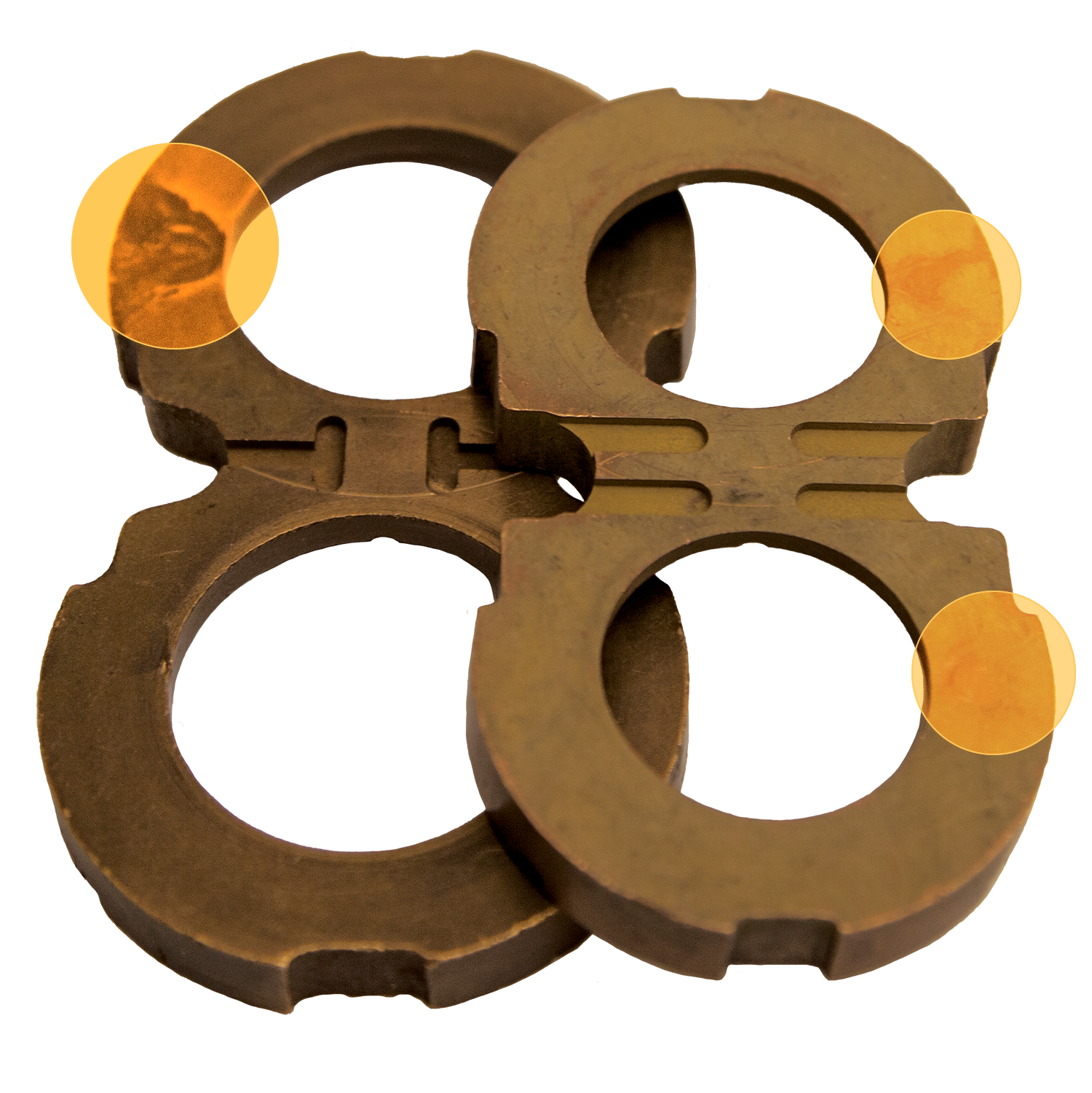
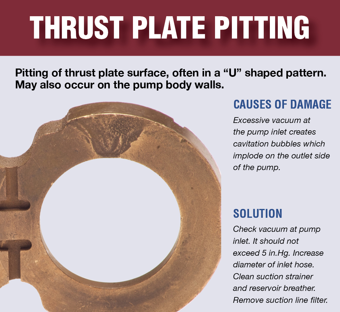
Let us consider the places where cavitation can occur. Since we already know that cavitation is primarily caused by a pressure drop, the first logical place coming to mind is hydraulic pump inlet. Truly, pressures low enough to cause cavitation can easily develop when suction conditions are compromised. If this is the case, the erosion is likely to be found inside the pump in the region where the positive displacement elements (like piston bores, or vane and gear chambers) transition from the suction side to the pressure side - i.e. the most probable place for the bubble collapse to happen. Like in this example, showing the typical horse-shoe wear pattern on the open loop pump valve plate, located between the kidney ports in the inlet-to-outlet transit area. When cavitation is prolonged and severe, the erosion spots can be found inside the positive displacement chambers and on the confining walls as well. In this cavitation case, for example, deep cavitation craters developed inside the bores of a piston pump barel.
Another factor, that can lead to hydraulic pump cavitation damage, but which is often overlooked, is the reaction time of certain open loop variable displacement pumps, typically when applied in closed center load sensing systems with frequent cycling between stand-by and full flow operation. Some pump models are capable of changing the displacement from zero to maximum so quickly, that the stationary column of oil in the suction line can"t keep up with the pump"s suddenly increased suction rate, thus creating momentary cavitation enabling conditions even in cases where the suction line is correctly sized. In these cases, if the system requirements allow it, the problem can be solved or mitigated by installing orifices in servo-piston lines thus effectively increasing the pump"s reaction time.
The next place for the cavtiation to develop would be the actuators, typically in systems where over-running load conditions can create suction and, consecutively, generate low pressure in one of the lines. The most common example would be hydraulic motors and rotary actuators, although cavitation can happen in cylinders as well. Correctly designed systems address this problem through application of some sort of over-center control and anti-cavitation arrangement, typically in the form of anti-cavitation check valves connected to a slightly pressurized (e.g. return) line to make sure the "starving" part of the actuator gets adequately filled with oil. But sometimes these valves fail, get misadjusted, or the load conditions are too fast for the anti-cavitation system to keep up. In these cases, if cavitation damage is discovered in the actuator, the anti-cavitation and load control measures must be double-checked. Here"s another "good example of a bad example" - a gerotor hydraulic motor, severely damaged by cavitation. In this particular case the fault lay in bad design - the load inertia wasn"t taken into consideration and no anti-cavitation system was used, resulting, as you can see, in severe erosion damage to the rotor.
Another cavitation-generating place to consider would be any place in a hydraulic system where high pressure oil needs to be throttled, producing narrow "oil-in-oil" jet. High velocity flow through restricted passages, like orifices, pressure control poppets, or spool metering notches, can easily create low pressure regions where cavitation can develop, and due to the fact that the originating cavitation cloud is also fast moving, the implosion area can cause erosion literally somewhere "around the corner". While hydraulic pump and actuator cavitation can be addressed by a number of solutions that effectively normalize the static pressure or even "supercharge" it in the problematic area, it is much harder and often impossible to do so in "throttling" cavitation cases, although it also must be said that more often than not the damage is likely to be negligible, since "normal" systems are built to avoid continuous high pressure throttling scenarios. But, as is always the case with hydraulics, it depends... And if unacceptable cavitation damage is indeed discovered downstream of a restriction point, the solution usually must be tailor-made for that particular case. Off the top of my head I can name a couple of possible fixes for such situations, for instance: changing the geometry of the problematic area so that the collapse phase happens farther from the confining walls, or maybe replacing a single restriction point with two connected in series.
Have a look at this very interesting "oil-in-oil jet" cavitation example. In this pump model the high speed stream originating from a decompression orifice of the valve plate is directed inside the pump case at an angle towards the end plate, having resulted in a relatively harmless, but nevertheless spectacular erosion spot. Here"s another example - an eroded overcenter valve spool. The cavitation damage is hardly noticeable at first glance, but it is actually extremely severe, with the erosion cavity of almost 4mm deep (!). If you zoom into the picture you can see that cavitation ate out a big chunk of material inside one of the spool notches.
For some reason there"s a strongly established opinion that whenever cavitation occurs you should hear a loud rattling noise comparable to something like pump "running with marbles inside". Throwing in my two cents, I can tell you that indeed, in case of a severe pump cavitation, yes, you will hear this distinctive loud noise, and if nothing is done immediately the pump will fail catastrophically, in fact in many of such cases when you arrive to diagnose the problem it"s "already too late"... However, I"ve also seen many components with signs of cavitation damage, that came from hydraulic systems that didn"t produce any humanly noticeable abnormal noise. And these systems, by the way, also appeared to have normal service history with acceptable component life spans.
Which brings me now to the revelation of my point of view on all this cavitation thing. Simply put - cavitation is extremely complex and generally bad, but - some degree of cavitation will happen in many, if not all, hydraulic systems, and we just have to learn how to live with it. Even the fact that you discovered signs of cavitation erosion during the last scheduled overhaul doesn"t necessarily mean that you have to run and "save the patria" by taking all possible and impossible measures to eliminate it no matter what. I believe that you should use common sense and consider costs when evaluating the presence of this type of damage, and only consider taking measures if the normally expected life span of a component was significantly shortened. Which is why it is also important to make sure that you have the correct information about how many operational hours led to the damage.
Obviously, if you hear loud and clear that a pump is cavitating, or when you find a motor partially destroyed by erosion after a short operation period, immediate investigation and corrective actions are necessary. But if you design your hydraulic system right and run it clean (the word "clean" here should be regarded as a collective term meaning everything that"s good - i.e. contaminant-free and correctly chosen oil, right temperature and operating conditions, adequate preventive maintenance in place - you know - clean), chances are that you will never have to worry about cavitation, and even if you eventually encounter minor cavitation erosion spots, most likely it will happen during a scheduled overhaul and to a part that was going to be replaced anyway, thus not having impacted the system"s expected life.
I used to say - "cavitation must be avoided at all costs", now I say - common sense and numbers, gentlemen, it"s all about common sense and numbers...

Pump cavitation is always a serious concern in the fluid power industry that leads to pump failure/breakdown. Cavitation occurs when liquid/oil contains dissolved gas and collapse during machine operation. In short, cavitation is the formation and collapse of air cavities in the liquid. The factors that affect air bubble formation are system pressure, temperature, fluid type, and external/internal leakages. This article will highlight all important facts about pump cavitation that includes its symptoms, method of prevention, and more.
What is pump cavitation? As we mentioned earlier, cavitation is the process of forming an air bubble in the hydraulic fluid. The primary reason for this issue is the partial pressure drop at the suction side of the pump caused while pumping fluid from the reservoir to the hydraulic pump. This pressure various will lead to the creation of a cavity inside the hydraulic pump. The produced air bubble will explode inside the pump causing system failure. There are numerous other causes for pump cavitation that includes the following.
Also, it is common for every hydraulic oil to contain 9% of dissolved air. The air will be pulled out of the oil when the pump doesn’t get sufficient oil. When this air bubble reaches a high-pressure area, it will explode or collapse.
Cavitation can be categorized based on its effect and different conditions. Based on the effects, cavitation can be of two types called inertial cavitation and non-inertial cavitation. Inertial cavitation will produce a shock wave when a bubble or void present in a liquid collapses. Whereas, non-inertial cavitation occurs when the air bubble in fluid changes its shape due to an acoustic field or some other type of energy input. Similarly, suction cavitation and discharge cavitation are two cavitation categories based on different conditions. I.e; suction cavitation occurs under high vacuum or low-pressure conditions that effects flow and discharge cavitation occurs when the pump’s discharge pressure becomes abnormally high.
The results of cavitation are excessive heat, reduced lubrication, violent implosions, friction and wear. These issues can cause serious damages to the pump leading to hydraulic system breakdown. The symptoms of cavitation are unusual sound while pump operation, presence of metal debris, and damage. When these symptoms occur, proper inspection and troubleshooting are necessary.
If pump cavitation is avoided, the pump will deliver maximum performance to a longer time period. Some tips for avoiding cavitation are mentioned below.

"Over two decades ago I was teaching a class in Salt Lake City, Utah. One of my students, a teacher from a technical college in northern California, was so impressed with my training “system” that he asked if I would make a duplicate of it for him. I did, and the rest is history! Today, you will find my hydraulic training systems in the USA, Canada, Australia, Africa, Asia, South America, and Saudi Arabia ... It is also the number one choice for Corporate Technical Training Centers.
FPTI™ is the fastest growing fluid power training systems provider in the world - ask any teacher who uses our system, or any student who has attended our workshops. There"s nothing else like it."

While it’s common for people to think of a pump’s inlet as sucking in oil, in reality, it is atmospheric pressure doing the work. In essence, the weight of the atmosphere pushes the oil out of the reservoir and into a region of lower pressure—the inlet. Once the oil is forced from the reservoir and through the inlet, it then moves the volume of liquid into a region of decreasing volume to create flow. For this process to begin, there must be minimum pressure at the inlet of a hydraulic pump, as shown in the diagram below.
As you can see, the inlet of a pump plays a large role in how well it operates. Unfortunately, those designing and maintaining pump systems can become so focused on downstream flow that they overlook proper inlet maintenance. This can result in degradation of inlet function and serious problems such as cavitation.
Cavitation occurs when the absolute pressure on the inlet side of the pump is too low and air is drawn out of the solution, creating bubbles in the oil. As these bubbles get pushed around to the high-pressure outlet side of the pump, they collapse. This creates localized shock waves that blow bits of material out of the pump. It can also result in excessive heat and reduced lubrication that leads to friction and wear over time.
Cavitation can cause pump failure and it can damage other components of your system, which is why it is critical to examine the condition of the pump"s inlet on a regular basis.
PSI versus PSIA. What’s the difference? PSI, or pounds per square inch, is a unit of measurement for pressure used in the United States. PSIA describes the absolute pressure in psi, including the pressure of the atmosphere. Absolute pressure is also referred to as total pressure.
The energy it takes to lift oil through the suction line (including pressure drop due to flow). We refer to this action as Phase 1 pressure, because it represents the amount of energy it takes to accelerate the fluid through the pumps internal pathways and keep the pump full.
In order for a pump to function, atmospheric pressure must be greater than Phase 1 pressure + NPSH. Every pump has its own specifications regarding acceptable minimum/maximum inlet pressure, but we can use the example below to illustrate how to calculate it.
To begin, assume that you are maintaining an 18 GPM hydraulic pump. The NPSH is equal to 12 PSIA with standard hydraulic oil and 1800 RPM per manufacturer’s specifications.
Each foot of oil lift requires approx. = 0.4 PSI. Fluid velocity is 3.8 feet per second. A typical lookup table shows there will be a 0.05 PSI drop due to the flow through the pipe.
Total loss of the inlet line during steady state is 0.4 PSI + 0.05 PSI, or 0.45 PSI. 14.7 – 0.45 = 14.25 PSI. Because this final number—14.25 PSI—is greater than the NPSH of 12 PSIA, you can rest assured the system is functioning well.
If we apply the same numbers to a variable-volume pump, the result will be less acceptable. Here’s why: Imagine the pump is not in demand and is therefore being held off stroke, meaning there is no flow. When the pump is suddenly needed, it will come on stroke, requiring the column of oil in the suction line to accelerate. This sudden change in demand requires the pump pressure to accelerate from static to a pressure that is strong enough to move the oil and prevent cavitation.
Assume the pump strokes on in 70 milliseconds (msec). The volume of liquid that has to accelerate is 1.5in^2 x 18.1” = 27.1 cubic inch (cu. in.). Note: Since the entire column of oil in the pipe has to accelerate, we used a measurement of 18.1” instead of 12.1”.
These calculations reveal that the system is fine, because the pump requires a minimum 12 PSIA at its inlet to operate effectively. However, if this system was installed at 2,300 feet above sea level (13.4 PSIA), the pump would cavitate whenever it came on stroke.
The above example assumes no losses due to other plumbing, however, it is not uncommon to see elbow fittings on pump ports, which could add to losses in the inlet line.
In addition to maintaining good inlet conditions, any small leak on the inlet will entrain air, which is also bad for the pump. Small leaks will cause a pump to lose prime whenever the system is shut off, which means it will start dry and run dry until prime is re-established. For this reason, it is never a good idea to install hydraulic pumps above the fluid level. Rather, hydraulic systems designs should ensure that the pump inlet is flooded, i.e. the oil level is above the pump inlet. A ball valve can be used to isolate the pump from the reservoir in case it needs service, and a limit switch can be used on the ball valve to prevent the system from running if the ball valve isn’t fully open.
This website is using a security service to protect itself from online attacks. The action you just performed triggered the security solution. There are several actions that could trigger this block including submitting a certain word or phrase, a SQL command or malformed data.

Pumps are at the heart of most industrial processes and the second most common machine in the world (after the electric motor). Because they are so common, pumps are often overlooked as a potential source of improved productivity or a cause of excess costs if not operated properly.
As with any machine, some problems can occur. A common problem in pumping systems is pump cavitation. Pump cavitation causes a number of issues including excess noise, vibration and energy usage, not to mention serious damage to the pump itself.
Imagine pinching a water hose and the water moves faster coming out but it is aerated and spread out. That is what happens with pump cavitation. It is a physical phenomenon that occurs when the pressure of the liquid incoming becomes lower than the vapor pressure of the liquid. A reduction in pressure is typically caused by increased speed of the fluid. When fluid pressure on the trailing side of the impeller blade (opposite the pump intake) falls below the vaporization point of the fluid, vapor bubbles begin to form. As the bubbles/cavities travel to the discharge side of the pump, moving to a high pressure area, the cavities implode. The imploding or collapsing of these bubbles trigger intense shockwaves inside the pump, causing damage to the impeller, vibration and excess noise.
These shock waves can cause mechanical damage to the impeller and pump, only increasing in severity over time and leading to potential pump failure. Factors that impact the degree of compression for the vapor bubbles are the speed and shape of the impeller.
When a pump operates with no flow through the pump due to a closed discharge valve or line blockage, a dead head has occurred. The pump recirculates the same water, causing water temperature to continually rise. If the pump continues to run in a dead-headed condition for too long, excessive heating can damage expensive seals and reduce the life of the pump.
Dead heading in a centrifugal pump can lead to explosions due to the energy being put into the liquid in the pump. Hydraulic overpressure and possible chemical reactions in the pump can also be caused by the overexertion of pressure. The same results can be caused by running the pump dry for an extended period, which can lead to cavitation.
Dead head means the outflow valve is open so the pump continues to circulate the same liquid over and over, which can damage the pump motor because the liquid can get too hot. The low power protection will work to detect this condition and trip to protect the motor.
Cavitation is similar in that the low power protection will detect it and trip and protect the motor as well. But this condition means that the pump is running dry and no liquid is there to pump. That too will cause the motor to overheat.
Cavitation damage can shorten the life of the pump impeller, mechanical seals, bearings and possibly other pump components. In other words, it will reduce the mean time between failure (MTBF), which will increase maintenance costs and pump downtime.
The most common way to identify pump cavitation is through sound or vibration. There is an audible sound similar to crackling that can be heard when this is occurring. Due to the bursting of the vapor bubbles, there is increased vibration experienced by the pump, which can also be observed.
Other ways to identify pump cavitation are temperature or power detection at the outboard motor. Pump cavitation means there is little to no liquid to pump while the pump itself continues. Pumping dry in this fashion, with building vapor pressure, will cause the motor to overheat—reducing motor life and potentially causing damage to the impeller and the pump itself.
Once an event is identified, it is important to identify the cause of the pressure drop and correct it. In most cases, the problem can be solved by simplifying the suction pipework, removing as many bends and valves as possible:
Most industries use large, highly complex pumps. Failure of these critical pumps could result in downtime costs that exceed $200,000 per day in operations cost alone, not counting the cost of equipment replacement due to damage. Therefore, users tend to closely monitor these pumps. Since cavitation can implode a pump and result in a major safety risk, users are always seeking reliable solutions that allow them to predict and prevent it.
As the shockwaves from the vapor bubbles bursting continue, the temperature will increase to the outboard motor. Motor management relays monitor and trip based on the temperature thresholds. Protections can range from the incoming power source feeding the motor to the individual pump or load. Motor management relays provide a high level of monitoring accuracy and power protection for the entire power system while maximizing uptime.
By preventing cavitation, users will increase the efficiency and life span of the pump. Remember, prevention is worth the time, so take the time to carry out a thorough maintenance program and it will save users in the long run.


 8613371530291