
what is hydraulic pump cavitation pricelist

Hydraulic pumps are used in various industries to pump liquid, fluid, and gas. Although this equipment features robust construction, it may fail at times due to various issues. Cavitation is one of the serious issues faced by this equipment. Like all other technical issues, right planning as well as troubleshooting will help avoid this issue to a large extent. What is pump cavitation and how to troubleshoot these it?
It is seen that many times, Strong cavitation that occurs at the impeller inlet may lead to pump failure. Pump cavitation usually affects centrifugal pumps, which may experience several working troubles. At times, submersible pumps may also be affected by pump cavitation.
Non-inertial Cavitation: This type of cavitation is initiated when a bubble in a fluid undergoes shape alterations due to an acoustic field or some other type of energy input.
Suction Cavitation: This cavitation is brought by high vacuum or low-pressure conditions that may affect the flow. These conditions will reduce the flow, and bubbles will be formed near the impeller eye. As these bubbles move towards the pump’s discharge end, they are compressed into liquid, and they will implode against the edge of the impeller.
Discharge Cavitation: Here, cavitation occurs when the pump’s discharge pressure becomes abnormally high, which in turn affects its efficiency. High discharge pressure will alter the flow of fluid, which leads to its recirculation inside the pump. The liquid will get stuck in a pattern between the housing, as well as the impeller, thereby creating a vacuum. This vacuum creates air bubbles, which will collapse and damage the impeller.
Sound: The pump affected by cavitation will produce a marble, rock, or gravel type of sound when in motion. The sound will begin as a small disturbance and its intensity will increase as the material slowly chips away from the surface of the pump.
Metallic Debris: If during the maintenance, you find metallic debris on the filter of the hydraulic pump then it may be a symptom of cavitation. One of the easiest ways to confirm it is to check the filter. If any debris is found, you should clean the entire system, and thoroughly inspect the pump.
Damage: This is one of the most obvious symptoms of cavitation. If you already know that the pump is damaged, you need to remove its filter, open, and inspect it thoroughly. If you find a lot of metal inside the filter, then flush the entire system, and check for damages in other parts, too.
If you notice any of the above-discussed symptoms, the next step would be to identify the causes, and rectify the changes in industrial pumps, otherwise, it may affect other components, too.
Avoid using suction strainers: These are designed to inhibit the ingestion of grime and dirt. However, these strainers do not succeed in their purpose, because they are not designed to entrap large particles. These large particles may get deposited in the flow path, thereby affecting the flow of fluid. The deposition also creates pressure, and produces bubbles, which may lead to cavitation.
Clean the reservoir: A dirty reservoir is one of the most common causes of cavitation. Various types of small and large objects may block the suction tube, and create pressure, thereby causing cavitation.
Use properly sized components: This is one of the important factors of cavitation prevention. If the inlet plumbing is too large, there will be too much liquid flow, which may trigger cavitation. Hence, check with the pump manufacturer to ensure that properly sized components are being used in the pump.
In addition to these preventive steps, you must source hydraulic pumps from a trusted manufacturer or supplier. JM Industrial is one of the industry-leading provider of unused and used industrial process equipment from industry-leading brands. These pumps can be availed at cost-effective prices.

Pumps are designed to produce enough flow and pressure to move a liquid from one location to the next. Sounds simple enough, but the internal system of a pump is complex. When you combine the complexity of the pump system with the wide-ranging properties of various fluids, the surrounding environment, and other factors, cavitation can occur.
Pump cavitation is a potentially damaging problem in pumps that are not properly configured or being used for their intended application. Here, we’ll explore what causes cavitation in pumps, the signs to look for, and ways to prevent it from happening.
Pumps are designed to pump liquids but, when the combined flow rate and pressure are inadequate or not conducive to the type of liquid being pumped, pockets or cavities can form, resulting in cavitation.
Some describe pump cavitation as the creation and collapse of the air bubbles in a fluid. While they may appear to look like air, those bubbles are technically a cavity, gaseous vapor, or vacuum. While cavitation is possible in all pump types, it is more common in centrifugal pumps where the bubbles quickly develop around the impeller’s axis. When the bubbles pass from the middle of the impeller to the outer edges, the centrifugal force creates higher pressure, causing those bubbles to quickly collapse or implode with great force.
Pump cavitation is the rapid succession and released energy of the implosions of gaseous cavities which cause an intense rattling sensation that can damage a pump.
Various conditions can make a pump more prone to cavitation. A clogged filter or strainer, for example, can easily restrict flow and lead to pump cavitation. Similarly, a restricted or flimsy inlet hose might collapse and cause issues. Fluid viscosity is a major contributor, too, especially when combined with the wrong hose. Imagine drinking a milkshake through a thin straw: the combination of the thick viscosity, pressure, and weak structure of the straw causes it to collapse and restricts the flow. Or consider if that straw has a pinhole in it; the leak would also affect flow and pressure. Similar phenomena can occur in pump systems.
That said, the inlet supply hose can’t be too rigid either. If you use a solid metal hose or a system is plumbed with hard PVC or copper piping, it could cause water hammering. Finding the right combination of dampening with a strong yet soft inlet hose or flexible PVC is ideal. Here at Pumptec, we use pulse hoses with metal springs inside them to add strength and rigidity. They’re less likely to collapse yet still offer the right level of flexibility.
The position of the reservoir tank also makes a difference. If the tank is positioned below the pump, the pump will need to decrease pressure to draw the fluid vertically through the inlet piping. The longer the inlet hose and the farther the vertical distance between the tank and the pump, the greater the chance of creating a vacuum and cavitation.
Heated liquids are a major contributor to cavitation, too, especially as the hot fluid approaches the boiling point and creates additional vapor pressure. In this instance, the liquid needs to be fed/pushed through a pump rather than drawn/pulled through it. The easiest way to achieve this is to have the tank containing the heated fluid elevated above the pump so that it is gravity fed into the pump system.
In all these instances, the flow is being disrupted or poorly executed, causing the discharge pressure to fall. The pump is basically being starved of fluid, resulting in cavitation.
Obvious signs of pump cavitation are excessive noise and vibration. The implosions and released energy within the system produce a loud growling sound, or it may sound and feel like gravel is circulating through the system.
Cavitation can damage seals, O-rings, and bearings, resulting in leaks and loss of pressure. On a centrifugal pump, the constant force of the implosions can erode the impeller and pump housing. Because of the added strain, the pump will also consume more power than it should.
On a positive displacement plunger pump, cavitation can erode seals and the metal around the poppet and seat on the check valves. If the pump body is made of anodized aluminum, which appears as a black coating, the black anodization will wear away upstream from the outlet check valve. In extreme cases, wear will occur outside of the main seal. If that happens, the pump will start sucking air, and bubbles — sometimes called washout — will form on the outlet.
Many of these issues can be prevented with proper maintenance and by selecting a pump that is designed for the intended use, accommodates the viscosity of the fluid being pumped, and has the proper configuration.
Some people think they just need to increase the size of the inlet hose. While it’s true that a hose that’s too small could cause cavitation, having a hose that’s too large could cause priming problems.
Centrifugal pumps have such high flow rates that it’s difficult to control their output, plus they have a lot of back pressure downstream that affects the amount of flow. Because of their lower flow rates, plunger pumps typically have fewer cavitation issues.
All in all, the pump pressure must be maintained above the liquid"s vapor pressure to avoid cavitation. In the end, the best tip for reducing cavitation is to work with a pump manufacturer to determine the proper use and placement for your application.
Contact the pump experts at Pumptec to discuss your pump challenges and how to overcome them with a solution that’s customized to your application. Get a head start by checking out our
It differs little if it is a pump on an engine, a hydraulic system, or any other application. Fact is, a broken pump can bring your entire operation to a standstill. Though pumps can fail due to age and use, the reality is that most are murdered, snatched from their prime with much life left in them. The culprit is cavitation, and it sends warning signs (excessive vibration, hammering, groaning, and whistling) but most are ignored.
Pump cavitation describes the formation of bubbles or cavities in the bulk fluid being moved that usually develops around a low-pressure area. This is the result of either an entrained gas in the liquid from the vapor pressure being exceeded or from a lack of flow. When the vapor bubbles collapse or implode, they strike at the speed of sound, creating the noise and vibration. This collision will erode the surfaces of the pump and impeller, and will attack the bearing, shaft alignment, and seal.
When you examine a failed pump, you will notice an appearance that resembles a sponge-like texture or missing material. Depending on the pump design and operating characteristics, the bearing may fall victim first, allowing excessive shaft movement and a collision of the impeller with the housing. Minor cavitation will result in decreased output or pressure. It is imperative that you are cognizant of the sound and pressure/flow characteristic of your pumps. Cavitation caught in the early stages will have minimal to no impact on pump life.
Suction side cavitation occurs when a pump is under low pressure or excessive vacuum. The pump is being starved of liquid and is not being fed enough flow. At that time, bubbles form at the eye of the impeller (where it connects to the shaft). As these bubbles move over to the discharge region, the fluid condition is altered and the bubbles are compressed into a liquid, causing them to implode against the face of the impeller. An impeller subjected to suction side cavitation will have pieces of material missing.
Discharge cavitation is the result of the discharge pressure being extremely high, so that it is difficult for the liquid to vacate the pump. It then circulates around the impeller and housing causing a very high vacuum at the wall and the formation of bubbles. Discharge cavitation allows the imploding bubbles to create intense shock waves, removing material from the housing and impeller. In extreme discharge cavitation cases, the impeller shaft may even break.
The most common cause is a flow restriction or running the pump at a speed that is out of its operating range. The flow issue can be either on the suction or pressure side, or a cumulative effect of both. Proper and timely maintenance of filters and screens goes a long way in preventing cavitation. Keep in mind that on a sprayer or other application with aged rubber hoses, they can be collapsing slightly and limiting suction performance and evoking cavitation.
Plumbing design such as pipe diameter and the amount of turns and the sharpness of them will potentially create either suction or discharge cavitation. You may have upgraded to a larger pump and now the factory piping cannot support it. No fluid likes to make turns; this will result in a flow restriction, both on the feed and discharge sides.
If a pump does fail, you need to take it apart and determine if it was the result of cavitation. On an engine, the coolant (water) pump seal can fail prematurely if the rpm is brought too high while the thermostat is closed. During that time, the coolant is being forced through a small bypass hose or passage. Excessive engine speed even under no load will cause the suction side of the pump to experience a very high vacuum and, over time, violate the pump seal and leak from the weep hole. On any engine, the rpm should be moderated when the coolant is below the temperature of the thermostat opening point.

To calculate the overall star rating and percentage breakdown by star, we don’t use a simple average. Instead, our system considers things like how recent a review is and if the reviewer bought the item on Amazon. It also analyzed reviews to verify trustworthiness.
The second leading cause of hydraulic pump failure, behind contamination, is cavitation. Cavitation is a condition that can also potentially damage or compromise your hydraulic system. For this reason, understanding cavitation, its symptoms, and methods of prevention are critical to the efficiency and overall health of not just your hydraulic pump, but your hydraulic system as a whole.
The product of excessive vacuum conditions created at the hydraulic pump’s inlet (supply side), cavitation is the formation, and collapse of vapors within a hydraulic pump. High vacuum creates vapor bubbles within the oil, which are carried to the discharge (pressure) side. These bubbles then collapse, thus cavitation.
This type of hydraulic pump failure is caused by poor plumbing, flow restrictions, or high oil viscosity; however, the leading cause of cavitation is poor plumbing. Poor plumbing is the result of incorrectly sized hose or fittings and or an indirect (not straight or vertical) path from the pump to the reservoir. Flow restrictions, for example, include buildup in the strainer or the use of an incorrect length of hose or a valve that is not fully open. Lastly, high oil viscosity—or oil that is too viscous—will not flow easily to the pump. Oil viscosity must be appropriate for the climate and application in which the hydraulic pump is being used.
The greatest damage caused by cavitation results from the excessive heat generated as the vapor bubbles collapse under the pressure at the pump outlet or discharge side. On the discharge side, these vapor bubbles collapse as the pressure causes the gases to return to a liquid state. The collapses of these bubbles result in violent implosions, drawing surrounding material, or debris, into the collapse. The temperature at the point of implosion can exceed 5,000° F. Keep in mind that in order for these implosions to happen, there must be high vacuum at the inlet and high pressure at the outlet.
Without a pressure condition at the outlet, or discharge side, these vapors merely form voids in the oil that reduce lubrication effectiveness. This results in friction and wear, which while seemingly mild compared to the excessive heat and violent implosions, can become detrimental over time.
Cavitation is usually recognized by sound. The pump will either produce a “whining” sound (more mild conditions) or a “rattling” sound (from intense implosions) that can sound like marbles in a can. If you’re hearing either of these sounds, you first need to determine the source. Just because you hear one of these two sounds doesn’t guarantee that your hydraulic pump is the culprit.
To isolate the pump from the power take-off (PTO) to confirm the source, remove the bolts that connect the two components and detach the pump from the PTO. Next, run the PTO with no pump and see if the sound is still present. If not, it is safe to assume your hydraulic pump is the problem.
Another sign you may be experiencing cavitation is physical evidence. As part of your general maintenance, you should be inspecting and replacing the hydraulic oil filter"s elements at regular intervals based on the duty cycle of the application and how often it is used. If at any time during the inspection and replacement of these elements you find metallic debris, it could be a sign that you’re experiencing cavitation in the pump.
The easiest way to determine the health of your complete hydraulic circuit is to check the filter. Every system should have a hydraulic oil filter somewhere in-line. Return line filters should be plumbed in the, you guessed it, return line from the actuator back to tank—as close to the tank as possible. As mentioned earlier, this filter will have elements that should be replaced at regular intervals. If you find metallic debris, your pump could be experiencing cavitation. You’ll then need to flush the entire system and remove the pump for inspection.
Conversely, if you’ve already determined the pump to be damaged, you should remove the filter element, cut it open, and inspect it. If you find a lot of metal, you’ll need to flush the entire system and keep an eye on the other components that may be compromised as a result.
Once cavitation has been detected within the hydraulic pump, you’ll need to determine the exact cause of cavitation. If you don’t, cavitation can result in pump failure and compromise additional components—potentially costing you your system.
Since the pump is fed via gravity and atmospheric pressure, the path between the reservoir and the pump should be as vertical and straight as possible. This means that the pump should be located as close to the reservoir as is practical with no 90-degree fittings or unnecessary bends in the supply hose. Whenever possible, be sure to locate the reservoir above the pump and have the largest supply ports in the reservoir as well. And don"t forget, ensure the reservoir has a proper breather cap or is pressurized (3–5 PSI), either with an air system or pressure breather cap.
Be sure the supply line shut-off valve (if equipped) is fully open with no restrictions. This should be a “full-flow” ball valve with the same inside diameter (i.d.) as the supply hose. If feasible, locate a vacuum gauge that can be T’d into the supply line and plumb it at the pump inlet port. Activate the PTO and operate a hydraulic function while monitoring the gauge. If it reads >5 in. Hg, shut it off, and resume your inspection.
If a strainer is present in the reservoir, inspect it, and remove any gunk or buildup that may be restricting supply flow. Next, check the inlet (suction) hose for any visible layline (descriptive markings on the hose). The industry standard “suction” hose nomenclature will read 100R4, or possibly SAER4. This will indicate the hose has an inner bladder that’s been vulcanized to a heavy spiral wire.
A hose with an inner bladder vulcanized to a heavy spiral is designed to withstand vacuum conditions as opposed to outward pressure. The layline will also denote the size of the hose (i.d.). You can use Muncie Power’s PPC-1 hydraulic hose calculator to determine the optimal diameter for your particular application based on operating flows.
Another consideration, in regards to the inlet plumbing, is laminar flow. To reduce noise and turbulence at the pump inlet, the length of the supply hose should be at least 10 times its diameter. This means that any type of shut-off valve or strainer at the reservoir should be at least 10 diameters from the pump inlet. A flared, flange-style fitting at the pump inlet can also reduce pump noise by at least 50 percent compared to a SAE, JIC, or NPT fitting.
Selecting the proper viscosity of hydraulic fluid for your climate and application is also critical. Oil that is too viscous will not flow as easily to the pump. Consult your local hydraulic oil supplier for help selecting the optimal fluid viscosity.
By maintaining a regular maintenance schedule, remaining vigilant for any signs or symptoms, and taking preventative measures, the good news is that you should be able to prevent cavitation and experience efficient operation for the duration of your pump’s lifespan.
Poor plumbing is the leading cause of cavitation and can be prevented by selecting a properly sized hose, choosing the appropriate fittings, ensuring the most direct, straight routing from the pump to the reservoir, etc.
Since joining the company in 2007, Ben Gillum has served in various capacities including shipping and receiving clerk, CS assembly, customer service manager, product application specialist, training and education assistant manager, and warranty and returns manager.

Cavitation is a common mode of wear in hydraulic pumps and control valves. The damage to components more often than not results in severe losses of service life times and flow efficiencies. Understanding the causes behind this phenomenon is the first step in developing solutions to combat its harmful effects.
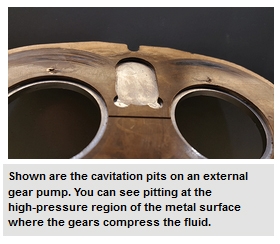
When the local static pressure in a fluid (inlet pressure) falls below the fluids vapour pressure (a characteristic property) at that particular temperature, vapour bubbles form in the fluid/hydraulic oil. Now, when we talk about bubbles, it is difficult to imagine that something so small can do incredible amounts of damage to hydraulic components. The vapour bubbles themselves pose no threat when floating around in the fluid. When the bubbles make it to the high pressure side of the pump/valve, however, they condense instantaneously and the bubbles collapse and produce hydraulic micro-jets which act similar to shockwaves. These micro-jets impinge on the metal surfaces, thereby destroying the material bonds (cavitation damage), and often result in (1) The creation of loud rolling noises (2) Vibration of the pump (3) The delivery of less flow and (4) Pitted erosion (as shown below).
The common causes of cavitation that allow the fluid to have a low static pressure can be grouped into three categories i.e. inlet inadequacies, fluid properties, and pump position.
Inlet inadequacies: These are often the case in systems when there is a restriction to the flow of the hydraulic fluid. Be sure to regularly look out for clogged strainers/filters, too many bends in the inlet line, and/or a collapsed inlet hose. Additionally, during the design and installation stage of your system, ensure the inlet pump lines are correctly sized and not too small.
Fluid properties:If your fluid is in a state that allows it to vaporise easily, the risk of cavitation is increased. This means that there is a presence of water particles and/or the hydraulic fluid is too viscous to be easily forced into the pump as a result of low temperature. Ensure that you use a good quality hydraulic oil, keep it isolated from external wet sources and, if necessary, heat it up before use as you would with warming up your rig’s engine.
Pump position: If your pump is too far away from the reservoir or too far above your reservoir you will have a low suction pressure allowing the formation of cavitation bubbles to occur. Make sure to use a pump with good filling characteristics or with a flooded suction. Alternatively, your design could incorporate a supercharged inlet.

Hydraulic Cavitation is, in many cases, an undesirable occurrence. It is the formation and collapse of air cavities in liquid. In hydraulic devices such as pumps, motors, etc. cavitation causes a great deal of noise, local erosion, damage to components, vibrations, increases oil contamination and a loss of efficiency. There is already established process of predicting cavitation using 3D simulation software. However, the model development is the time-consuming process as well as prediction process is component /subsystem level and cannot be done for various duty cycle operations at architecture level. That requires exploring our research in 1D simulation technique for prediction of cavitation. In this research, we have developed and implemented a methodology/mathematical model for the prediction of hydraulic cavitation in hydraulic system using a 1D simulation technique. For simulation purpose, we have taken an example of simple hydraulic system and predicted the cavitation in one of the component/subsystem of hydraulic system for ambient conditions. The mathematical model proposed based on mass transport equations of vapor, liquid and gas, Rayleigh-Plesset equations, Singhal model and bubble density equations. From simulation results, we conclude that cavitation can be predicted based on bubble dynamics (from estimation of the nuclei of bubble to its collapse), vapor volume fraction, collapse pressure generated at the time of collapse of bubble and maximum impact pressure on the wall of component. The simulation results are validated using 3D simulation software. This method will help to predict cavitation at early stages of design of hydraulic system. Future work consist of the estimation of erosion rate and material damage (life and performance).

The phenomenon of cavitation consists in the disruption of continuity in the liquid where there is considerable local reduction of pressure. The formation of bubbles within liquids (cavitation) begins even in the presence of positive pressures that are equal to or close to the pressure of saturated vapor of the fluid at the given temperature.
Various liquids have different degrees of resistance to cavitation because they depend, to a considerable degree, upon the concentration of gas and foreign particles in the liquid.
The mechanism of cavitation can be described as follows: Any liquid will contain either gaseous or vaporous bubbles, which serve as the cavitation nuclei. When the pressure is reduced to a certain level, bubbles become the repository of vapor or of dissolved gases.
The immediate result of this condition is that the bubbles increase rapidly in size. Subsequently, when the bubbles enter a zone of reduced pressure, they are reduced in size as a result of condensation of the vapors that they contain.
This process of condensation takes place fairly quickly, accompanied by local hydraulic shocks, the emission of sound, the destruction of material bonds and other undesirable phenomena. It is believed that reduction in volumetric stability in most liquids is associated with the contents of various admixtures, such as solid unwetted particles and gas-vapor bubbles, particularly those on a submicroscopic level, which serve as cavitation nuclei.
A critical aspect of the cavitation wear process is surface destruction and material displacement caused by high relative motions between a surface and the exposed fluid. As a result of such motions, the local pressure of the fluid is reduced, which allows the temperature of the fluid to reach the boiling point and small vapor cavities to form.
When the pressure returns to normal (which is higher than the vapor pressure of the fluid), implosions occur causing the cavity or vapor bubbles to collapse. This collapse of bubbles generates shock waves that produce high impact forces on adjacent metal surfaces and cause work hardening, fatigue and cavitation pits.
Thus, cavitation is the name given to a mechanism in which vapor bubbles (or cavities) in a fluid grow and collapse due to local pressure fluctuations. These fluctuations can produce a low pressure, in the form of vapor pressure of the fluid. This vaporous cavitation process occurs at approximately constant temperature conditions.
Vaporous cavitation is an ebullition process that takes place if the bubble grows explosively in an unbounded manner as liquid rapidly changes into vapor. This situation occurs when the pressure level goes below the vapor pressure of the liquid.
Gaseous cavitation is a diffusion process that occurs whenever the pressure falls below the saturation pressure of the noncondensable gas dissolved in the liquid. While vaporous cavitation is extremely rapid, occurring in microseconds, gaseous cavitation is much slower; the time it takes depends upon the degree of convection (fluid circulation) present.
Cavitation wear occurs only under vaporous cavitation conditions - where the shock waves and microjets can erode the surfaces. Gaseous cavitation does not cause surface material to erode.
It only creates noise, generates high (even molecular level cracking) temperatures and degrades the chemical composition of the fluid through oxidation. Cavitation wear is also known as cavitation erosion, vaporous cavitation, cavitation pitting, cavitation fatigue, liquid impact erosion and wire-drawing.
Cavitation wear is a fluid-to-surface type of wear that occurs when a portion of the fluid is first exposed to tensile stresses that cause the fluid to boil, then exposed to compressive stresses that cause the vapor bubbles to collapse (implode).
This collapse produces a mechanical shock and causes microjets to impinge against the surfaces, unifying the fluid. Any system that can repeat this tensile and compressive stress pattern is subject to cavitation wear and all the horrors accompanying such destructive activity.
Cavitation wear is similar to surface fatigue wear; materials that resist surface fatigue (hard but not brittle substances) also resist cavitation damage.
Liquid is the medium that causes cavitation wear. Cavitation wear does not require a second surface; it requires only that high relative motion exists between the surface and the fluid. Such motion reduces the local pressure in the fluid. When the liquid reaches its boiling point and ebullition occurs, vapor bubbles form, which produces cavitation.
Each vapor cavity lasts a short time because almost any increase in pressure causes the vapor in the bubble to condense instantaneously and the bubble to collapse and produce a shock wave. This shock wave then impinges on adjacent metal surfaces and destroys the material bonds.
The shock wave first produces a compressive stress on the solid surface, and then when it is reflected, produces a tensile stress that is normal to the surface.
Figure 1 depicts the collapse of a vapor bubble and the birth of a microjet. Cavitation is generally found where a hydrodynamic condition, characterized by a sudden and gross change in hydrostatic pressure, exists. Because ebullition can occur the instant pressure drops, vapor bubbles form and collapse frequently and quickly.
Entrained air and dust particles in the fluid serve as nucleation sites for the formation of vapor cavities. These nuclei can be small gas-filled pockets in the crevices of the container or simply gas pockets on contaminant particles moving freely in the flow stream. Therefore, all confined fluids may contain sufficient impurities to produce cavitation.
Small voids near the surface or flow field, where minimum pressure exists, indicate that cavitation has begun. Once initiated, bubbles continue to grow as long as they remain in low-pressure regions. As the bubbles travel into high-pressure regions, they collapse, producing intense pressures and eroding any solid surfaces in the vicinity.
Equipment users can detect cavitation audibly, visually, by acoustical instrumentation, by machine vibration sensors, through sonoluminescence measurement or by a decrease or change in performance from that produced under single-phase flow conditions (for example, loss of flow, rigidity and response).
Under cavitating flow conditions, the wear rate can be many times greater than that caused by erosion and corrosion alone. Cavitation wear can destroy the strongest of materials - tool steels, stellites, etc. Such damage can occur rapidly and extensively.
The amount of damage that cavitation causes depends on how much pressure and velocity the collapsed bubbles create. As a result of this pressure and velocity, the exposed surface undergoes a variety of widely varying intensities.
Each imposition lasts only a short time; the impulse magnitudes and collapse times are greater for larger bubbles at given collapsing pressure differentials. Thus, the greater the tensile stress on the fluid (the lower the static pressure), the larger the bubbles, the more intense the cavitation and the more serious the damage.
The impulses that result when vapor bubbles form and collapse cause individual symmetrical craters and permanent material deformations when the collapse occurs next to the surface. Consequently, cavitation damage, like fatigue failure, has several periods of activity:
So the region where damage occurs is often quite separate from the region in which cavities are created - often leading to an incorrect diagnosis of the problem. Cavitation wear is mechanical in nature and cannot occur without the application of the tensile and compressive stresses.
In leakage paths (across seals, valve seats and spool lands) where high velocities cause pressure levels to drop below the vapor pressure of the fluid (a cavitation condition often referred to as wire-drawing) and
In all devices where fluid flow is subjected to sharp turns, reduction in cross-sections with subsequent expansions (in cocks, flaps, valves, diaphragms) and other deformations.
Cavitation disturbs the normal operating conditions of fluid-type mechanical systems and destroys the surfaces of components. The process consists of cavities forming when pressures are low, the growth of subsequent bubbles as pressure stabilizes and finally the collapse of the bubbles when the cavities (gaseous or vaporous bubbles) are exposed to high-pressure.
Note that the pressure drop across the component is the driving force for cavitation wear. Figure 2 depicts the cavitation process that occurs in a gear pump and in a spool valve showing how cavities generate, grow and collapse in fluid-type components.
In cavitation wear, microcracks propagate to the point where the material can no longer withstand the impulse load that the imploding vapor bubbles impose. Therefore, particles finally break off and enter the system.
As with any fatigue failure, microcracks first form at stress risers (notches, tears, undercuts, welding defects, etc.) or at heterogeneous areas of the material (such as at the directionality of metal flow, inclusions, and decarburized sections).
Therefore, a rough surface is prone to cavitation wear and because pittings and a rough profile characterize the cavitation damage, the damage increases as the surface becomes rougher.
The most basic means of combating cavitation wear is to minimize the tensile stress on the fluid. In other words, the equipment users must lower the level of refraction or vacuum conditions in zones of possible cavitation. In particular, the following steps may be appropriate:
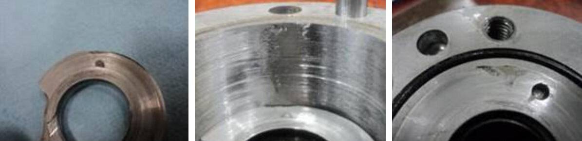
In many cases, design engineers can minimize cavitation damage by properly selecting fabrication materials. For example, stainless steel may be selected instead of aluminum (Figure 3) and use hard facing with a cavitation-resistant alloy on the exposed surface. Rubber and other elastomeric coatings have also helped minimize cavitation wear. Despite their low resistance to cavitation, these surfaces reflect the shock wave without causing intense damage.
The size of the particles generated by cavitation wear is a function of the Brinell hardness of the exposed material. The largest particles occur during the accumulation period. The slopes of the cumulative particle size distribution curves increase as the strain energy of the material increases. The average size of the particles produced by cavitation decreases as the cavitation intensity increases.
When investigating a cavitation problem in a fluid system, you must identify all possible sources of low pressure (vacuum), high temperature (heat), and locations where air might be ingressing. The following list should serve as a guideline for identifying low pressure areas in a fluid system:
Reservoirs - sites where mechanical (agitation) type air entrainment occurs, swirling fluid exists, fluid impingement on liquid or solid surfaces, pressurized reservoir conditions, cyclonic flow at pump suction port, critical altitude (angled reservoir) occurring during operation that exposes the pump suction port to the atmosphere, jostling of the fluid due to movement over rough terrain and/or low reservoir fluid level that expose the pump suction port to the atmosphere.
Pump - small diameter conduits and/or ports, restrictive flow passages, flow diversions, and/or long suction line conditions, poor pump filling characteristics (restrictive internal flow passages, high pumping speed, overly large flow displacement); altitude too high to provide sufficient reservoir pressure to supply the pump at rated flow conditions; inadequate suction head to lift fluid to pump inlet level (that is, elevation between fluid level and pump intake too great), insufficient suction head to accelerate reservoir fluid to the rated flow conditions of the pump (non-responsive to the pump displacement demands).
Valves - jets discharging from orifices into limited flow space, streamline flow through channels terminating in chambers where low pressure is at the downstream walls of the valve, and/or throttle valves discharging into a low pressure (return line) conduit.
Actuators (extended seals) - air passing rod seals, air desorption existing, and/or vaporous cavities forming when negative loading occurs due to external inertial loads.

Hydraulic Cavitation is, in many cases, an undesirable occurrence. It is the formation and collapse of air cavities in liquid. In hydraulic devices such as pumps, motors, etc. cavitation causes a great deal of noise, local erosion, damage to components, vibrations, increases oil contamination and a loss of efficiency. There is already established process of predicting cavitation using 3D simulation software. However, the model development is the time-consuming process as well as prediction process is component /subsystem level and cannot be done for various duty cycle operations at architecture level. That requires exploring our research in 1D simulation technique for prediction of cavitation. In this research, we have developed and implemented a methodology/mathematical model for the prediction of hydraulic cavitation in hydraulic system using a 1D simulation technique. For simulation purpose, we have taken an example of simple hydraulic system and predicted the cavitation in one of the component/subsystem of hydraulic system for ambient conditions. The mathematical model proposed based on mass transport equations of vapor, liquid and gas, Rayleigh-Plesset equations, Singhal model and bubble density equations. From simulation results, we conclude that cavitation can be predicted based on bubble dynamics (from estimation of the nuclei of bubble to its collapse), vapor volume fraction, collapse pressure generated at the time of collapse of bubble and maximum impact pressure on the wall of component. The simulation results are validated using 3D simulation software. This method will help to predict cavitation at early stages of design of hydraulic system. Future work consist of the estimation of erosion rate and material damage (life and performance).
In this writing we will explain these questions? What is a submersible water pump? What is the price? What are its applications and features? Stay with us to know the answers. A submersible pump is a sort of sealed pumping equipment that pushes water through the pumping process rather than pulling it. As the name suggests, the pump may work this way because it is totally submerged in the liquid to be pumped. Due to this, the pump may be lowered into a deep pit without experiencing issues like pump cavitation, which can harm moving parts and produce steam bubbles. There are many industrial and commercial uses for submersible pumps.
The whirling impeller and rotating vanes of centrifugal pumps are typically composed of metal. These vanes help the propellant fluid receive energy from the engine. The fluid accelerates when it enters the impeller because of the rotation of the impeller. High speed fluid finally leaves the impeller blades, where the kinetic energy is often transferred to pressure.
There are single-stage and multi-stage submersible pumps. A motor is housed in each stage"s housing, which is mechanically sealed to stop leaks. The body of the motor extends into a tube or hose heading to the surface, and it is connected to a cable that produces electrical power to run the motor. Submersible pumps can be linked to various pipes, hoses, or wires depending on the task and the liquid being pumped. Housings for submersible pumps can be constructed from a variety of metals, including polymer, stainless steel, and chrome. The fact that the cover is hermetically sealed is its most crucial feature.
The electric submersible pumping principle underlies the operation of many submersible pumps (ESP). This is accomplished by lowering the flow pressure, which lowers the pressure at the submersible pump"s location at the bottom of the shaft. Since ESP system motors must function at high temperatures (up to 300°F) and pressures, particularly deep wells like oil wells are frequently employed. In more recent advances, coiled tubular umbilicals may be used to power deep-well motors; but, because special electrical cables are required, their operation may be relatively expensive. Additionally, compared to other submersible pump motors, the power consumption is significantly larger, and the pump operates to a great extent that prevents particles and sand from entering.
A device with a sealed motor linked to the water ump body is referred to as an electric submersible pump (ESP). The fluid that will be pushed is submerged beneath the entire system. This kind of pump"s key benefit is that it doesn"t suffer from pump cavitation, a problem brought on by significant height differences between the pump and the fluid surface. Submersible pumps force the fluid to the surface as opposed to jet pumps, which generate a vacuum and rely on atmospheric pressure. In heavy oil applications, where a liquid under pressure from a surface is utilised to drive the bore of a hydraulic motor and hot water is used as the driving fluid, floats are employed in place of electric motors. Electric submersible pumps are multistage centrifugal pumps that run vertically. The diffuser, where kinetic energy is transformed into pressure, is where the impeller-accelerated fluid loses kinetic energy. This is how radial and mixed flow pumps operate primarily. Instead of being an electric motor, the motor in HSP is hydraulic, and it can either be closed cycle (keeping the power fluid and generated fluid apart) or open cycle (mixing the power fluid and generated fluid cavity and surface separation). A mechanical coupling located at the pump"s base connects the pump shaft to the gas separator or protector. The pump stage raises fluid that enters through the input plate of the pump. Radial bearings (bushings), which are dispersed throughout the shaft and support the pump shaft radially, are among the additional components.
In order to produce a sort of "artificial lift" that can function over a wide variety of flow rates and depths, submersible pumps are utilized in the oil industry. In comparison to natural production, the well can produce much more oil by lowering the pressure at the bottom of the well (by decreasing the flow pressure in the bottom hole or raising the drawdown). When discussing hydraulic power, ESP (Electric Submersible Pumps) or HSP are meant (Hydraulic Submersible Pumps).
A mechanical tool called a pump is used to transfer fluid like water from one location to another. New pumps for new applications such as submersible pumps, maintenance, and repairs are all offered by Pump Service. We are aware that in some circumstances, our clients may require a submersible pump. Here, we delve deeper into the definition, operation, and applications of submersible pumps. A submersible pump is what? Submersible pumps, as their name suggests, are pumps that are fully submerged in the fluid they are moving. This differs from a pump that is outside the fluid being pumped. The pump motor of Lethbridge"s submersible pumps is linked to the hull and sealed, making them entirely submersible. How are submersible pumps operated? Submersible pumps operate by pushing the fluid, as opposed to exterior pumps, which must bring the fluid to the surface. The impeller inside the pump body begins to rotate as soon as the submersible water pump is turned on. Water is drawn into the pump body by this rotation. The water is subsequently forced toward the surface by the impeller through the diffuser. What benefits can submersible pumps offer? Due to their numerous potential advantages over external pumps, Lethbridge"s submersible pumps are used in specific circumstances. The fact that totally submersible pumps don"t need priming is one of its many benefits. Since the water pressure helps transport the fluid into the pump, submersible pumps are more energy-efficient than external pumps. Submersible pumps also have the critical benefit of having a longer lifespan than external pumps due to the absence of mechanical issues.
Due to its benefits, submersible pumps have a wide range of possible uses in residential, commercial, and industrial settings. In Lethbridge, submersible pumps are most frequently used for, but not limited to:
The septic tank is used to pump out sewage. Electricity supply for irrigation systems used in industry and agriculture. Pumping water out of sections of construction sites that are waterlogged. It moves oil from underground to a facility for refining and storing it on the surface. In order to fill above-ground storage tanks, it pumps water from deep underground wells.
You may rely on Pump Services to identify the best pumping solution for your requirements if you require a submersible pump. At Lethbridge, we provide a broad selection of pumps from renowned brands like Jacuzzi, Monarch, Armstrong, Bell & Gossett, including submersible pumps. Inform us of the application you desire. We are delighted to suggest the ideal submersible pump for your requirements.

Pump cavitation is always a serious concern in the fluid power industry that leads to pump failure/breakdown. Cavitation occurs when liquid/oil contains dissolved gas and collapse during machine operation. In short, cavitation is the formation and collapse of air cavities in the liquid. The factors that affect air bubble formation are system pressure, temperature, fluid type, and external/internal leakages. This article will highlight all important facts about pump cavitation that includes its symptoms, method of prevention, and more.
What is pump cavitation? As we mentioned earlier, cavitation is the process of forming an air bubble in the hydraulic fluid. The primary reason for this issue is the partial pressure drop at the suction side of the pump caused while pumping fluid from the reservoir to the hydraulic pump. This pressure various will lead to the creation of a cavity inside the hydraulic pump. The produced air bubble will explode inside the pump causing system failure. There are numerous other causes for pump cavitation that includes the following.
Also, it is common for every hydraulic oil to contain 9% of dissolved air. The air will be pulled out of the oil when the pump doesn’t get sufficient oil. When this air bubble reaches a high-pressure area, it will explode or collapse.
Cavitation can be categorized based on its effect and different conditions. Based on the effects, cavitation can be of two types called inertial cavitation and non-inertial cavitation. Inertial cavitation will produce a shock wave when a bubble or void present in a liquid collapses. Whereas, non-inertial cavitation occurs when the air bubble in fluid changes its shape due to an acoustic field or some other type of energy input. Similarly, suction cavitation and discharge cavitation are two cavitation categories based on different conditions. I.e; suction cavitation occurs under high vacuum or low-pressure conditions that effects flow and discharge cavitation occurs when the pump’s discharge pressure becomes abnormally high.
The results of cavitation are excessive heat, reduced lubrication, violent implosions, friction and wear. These issues can cause serious damages to the pump leading to hydraulic system breakdown. The symptoms of cavitation are unusual sound while pump operation, presence of metal debris, and damage. When these symptoms occur, proper inspection and troubleshooting are necessary.
If pump cavitation is avoided, the pump will deliver maximum performance to a longer time period. Some tips for avoiding cavitation are mentioned below.

All Rights Reserved. Reproduction of any part of this website, including design and content, without written permission is strictly prohibited. Trade Marks and Trade Names contained and used in this Website are those of others, and are used in this Website in a descriptive sense to refer to the products of others. Use of this Web site constitutes acceptance of our User Agreement and Privacy Policy
TRADEMARK DISCLAIMER: Tradenames and Trademarks referred to within Yesterday"s Tractor Co. products and within the Yesterday"s Tractor Co. websites are the property of their respective trademark holders. None of these trademark holders are affiliated with Yesterday"s Tractor Co., our products, or our website nor are we sponsored by them. John Deere and its logos are the registered trademarks of the John Deere Corporation. Agco, Agco Allis, White, Massey Ferguson and their logos are the registered trademarks of AGCO Corporation. Case, Case-IH, Farmall, International Harvester, New Holland and their logos are registered trademarks of CNH Global N.V.

A submersible pump (or electric submersible pump (ESP)) is a device which has a hermetically sealed motor close-coupled to the pump body. The whole assembly is submerged in the fluid to be pumped. The main advantage of this type of pump is that it prevents pump cavitation, a problem associated with a high elevation difference between the pump and the fluid surface. Submersible pumps push fluid to the surface, rather than jet pumps, which create a vacuum and rely upon atmospheric pressure. Submersibles use pressurized fluid from the surface to drive a hydraulic motor downhole, rather than an electric motor, and are used in heavy oil applications with heated water as the motive fluid.
Electric submersible pumps are multistage centrifugal pumps operating in a vertical position. Liquids, accelerated by the impeller, lose their kinetic energy in the diffuser, where a conversion of kinetic to pressure energy takes place. This is the main operational mechanism of radial and mixed flow pumps. In the HSP, the motor is a hydraulic motor rather than an electrical motor, and may be closed cycle (keeping the power fluid separate from the produced fluid) or open cycle (mingling the power fluid with the produced fluid downhole, with surface separation).
enter the pump through an intake screen and are lifted by the pump stages. Other parts include the radial bearings (bushings) distributed along the length of the shaft, providing radial support to the pump shaft. An optional thrust bearing takes up part of the axial forces arising in the pump, but most of those forces are absorbed by the protector"s thrust bearing.
There are also screw-type submersible pumps, there is a steel screw which is used as a working element in them. The screw allows the pump to work in water with a high sand content and other mechanical impurities.
Submersible pumps are found in many applications. Single stage pumps are used for drainage, sewage pumping, general industrial pumping and slurry pumping. They are also popular with Pond filters. Multiple stage submersible pumps are typically lowered down a borehole, and most typically used for residential, commercial, municipal and industrial water extraction (abstraction), water wells and in oil wells.
Pumps in electrical hazardous locations used for combustible liquids or for water that may be contaminated with combustible liquids must be designed not to ignite the liquid or vapors.
Submersible pumps are used in oil production to provide a relatively efficient form of "artificial lift", able to operate across a broad range of flow rates and depths.
ESP systems consist of both surface components (housed in the production facility, for example an oil platform), and sub-surface components (found in the well hole). Surface components include the motor controller (often a variable speed controller), surface cables and transformers. The subsurface components are deployed by attaching to the downhole end of a tubing string, while at the surface, and then lowered into the well bore along with the tubing.
A high-voltage (3 to 5 kV) alternating-current source at the surface drives the subsurface motor. Until recently, ESPs had been costly to install due to the requirement of an electric cable extending from the source to the motor. This cable had to be wrapped around jointed tubing and connected at each joint. New coiled tubing umbilicals allow for both the piping and electric cable to be deployed with a single conventional coiled tubing unit. Cables for sensor and control data may also be included.
The subsurface components generally include a pump portion and a motor portion, with the motor downhole from the pump. The motor rotates a shaft that, in turn, rotates pump impellers to lift fluid through production tubing to the surface. These components must reliably work at high temperatures of up to 300 °F (149 °C) and high pressures of up to 5,000 psi (34 MPa), from deep wells of up to 12,000 feet (3.7 km) deep with high energy requirements of up to 1000 horsepower (750 kW). The pump itself is a multi-stage unit, with the number of stages being determined by the operating requirements. Each stage includes an impeller and diffuser. Each impeller is coupled to the rotating shaft and accelerates fluid from near the shaft radially outward. The fluid then enters a non-rotating diffuser, which is not coupled to the shaft and contains vanes that direct fluid back toward the shaft. Pumps come in diameters from 90 mm (3.5 inches) to 254 mm (10 inches) and vary between 1 metre (3 ft) and 8.7 metres (29 ft) in length. The motor used to drive the pump is typically a three-phase, squirrel cage induction motor, with a nameplate power rating in the range 7.5 kW to 560 kW (at 60 Hz).
ESP assemblies may also include: seals coupled to the shaft between the motor and pump; screens to reject sand; and fluid separators at the pump intake that separate gas, oil and water.
Submersible pump cable are electrical conductors designed for use in wet ground or under water, with types specialized for pump environmental conditions.
A submersible pump cable is a specialized product to be used for a submersible pump in a deep well, or in similarly harsh conditions. The cable needed for this type of application must be durable and reliable, as the installation location and environment can be extremely restrictive as well as hostile. As such, submersible pump cable can be used in both fresh and salt water. It is also suitable for direct burial and within well castings. A submersible pump cable"s area of installation is physically restrictive. Cable manufacturers must keep these factors in mind to achieve the highest possible degree of reliability. The size and shape of submersible pump cable can vary depending on the usage and preference and pumping instrument of the installer. Pump cables are made in single and multiple conductor types and may be flat or round in cross section; some types include control wires as well as power conductors for the pump motor.
"A Historical Perspective of Oilfield Electrical Submersible Pump Industry". esppump.com. ESP pump.com. September 17, 2012. Retrieved November 16, 2017. With three employees, Arutunoff built and installed the first ESP in an oil well in the El Dorado field near Burns, Kansas.
"A brief history of pumps". worldpumps.com. Elsevier Ltd. March 23, 2009. Retrieved November 16, 2017. 1929: Pleuger pioneers the submersible turbine pump motor
Lyons, William C., ed. (1996). Standard Handbook of Petroleum & Natural Gas Engineering. Vol. 2 (6 ed.). Gulf Professional Publishing. ISBN 0-88415-643-5.


 8613371530291