
kelly bushing oil and gas free sample
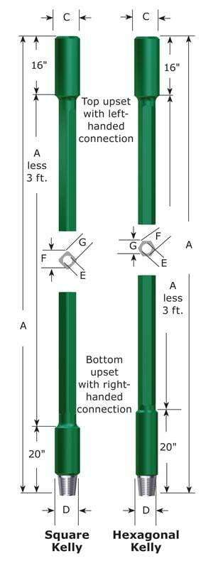
The square or hexagonal shaped steel pipe connecting the swivel to the drill string. The kelly moves through the rotary table and transmits torque to the drill string.
Source: API RP 7G, Recommended Practice for Drill Stem Design and Operating Limits, Upstream Segment, Sixteenth Edition, August 1998 (Addendum 2: September 2009). Global Standards
Square- or hexagonal-shaped steel pipe connecting the swivel to the drill pipe. NOTE The kelly moves through the rotary table and transmits torque to the drill stem.
Square or hexagonally shaped steel pipe connecting the swivel to the drill pipe that moves through the rotary table and transmits torque to the drill stem.
The square, hexagonal or other shaped steel pipe connecting the swivel to the drill pipe. The kelly moves through the kelly bushings, rotary table and rotates the drill string.
Source: API RP 54, Recommended Practice for Occupational Safety for Oil and Gas Well Drilling and Servicing Operations, Third Edition, August 1999 (2007). Global Standards
The uppermost component of the drill string; the kelly is an extra-heavy joint of pipe with flat or fluted sides that is free to move vertically through a “kelly bushing” in the rotary table; the kelly bushing imparts torque to the kelly and thereby the drill string is rotated.
The uppermost component of the drill string; the kelly is an extra-heavy joint of pipe with flat or fluted sides that is free to move vertically through a “kelly bushing” in the rotary table; the kelly bushing imparts torque to the kelly and thereby the drill string is rotated.
Source: API RP 64, Recommended Practice for Diverter Systems Equipment and Operations, Second Edition, November 2001 (March 1, 2007). Global Standards
“Kelly” means a 3 or more sided shaped steel pipe connecting the swivel to the drill pipe. The kelly moves through the kelly bushing and the rotary table and transmits torque to the drill string. [Mich. Admin. Code R 408 (2013)].
The square or other shaped steel pipe connecting the swivel to the drill pipe. The kelly moves through the rotary table and transmits torque to the drill string.

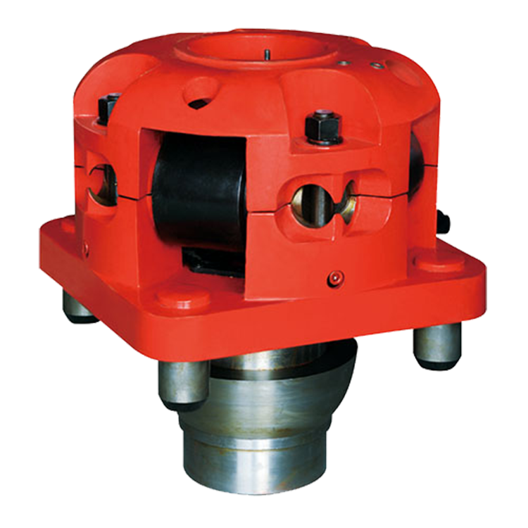
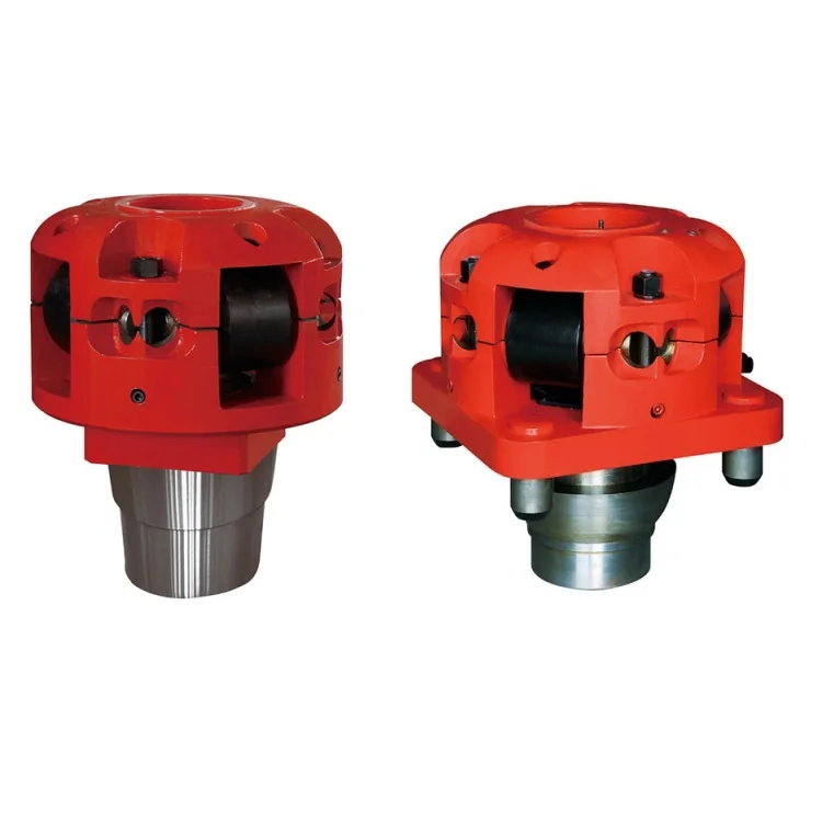
Kelly bushing is that elevated device positioned right on top of the rotary table and used to transmit torque from the rotary table to the kelly. The kelly bushing is designed to be the connection between the rotary table and the kelly. The kelly is a 4 or 6 sided steel pipe.
The purpose of the rotary table is to generate the rotary action (torque) and power necessary to rotate the drillstring and drill a well. The torque generated by the rotary table is useless if it is not transferred to the kelly (the drillstring is connected to the kelly).
Hence, through the kelly bushing the torque generated at the rotary table is transferred to the kelly. To achieve this connection, the inside profile of the kelly bushing matches the outer profile of the kelly so that the kelly fits or “sits” comfortably in the kelly bushing.
There are various designs for the kelly bushing including the split type, the pin-drive type and the square-drive type. Each of these designs has different ways in which they are connected and disconnected from the rotary table.
The internal diameter of the kelly bushing can be cut into the shape of a square (4-sided) or a hexagon (6-sided) depending on the outer shape of the kelly that will be used. The internals of a Kelly bushing is designed to resemble the outer shape of a Kelly just like the insides of a key lock is cut to exactly match the outer shape of the key.
The kelly bushing is not designed to hold tightly onto the Kelly; the kelly is still permitted to move up and down through the kelly bushing. This requirement is a must since drilling cannot progress if the kelly remains on a fixed spot. As the well is drilled deeper, the kelly also moves downward through the Kelly bushing.
The kelly bushing is sometimes used as a reference point from which depth measurements can be taken. All depths must be recorded with respect to a reference point; the kelly bushing (KB) is one of the depth references used in the oil and gas industry.
The top of the kelly bushing is normally used as the depth reference.For example, 7500ft KB means 7500ft below the kelly bushing or 7500ft measured from the top of the kelly bushing down to that point in the well.
In some other cases, depths could be recorded as 7500ft MDBKB meaning 7500ft measured depth below the kelly bushing. This is mostly used when the measured depth is different from the true vertical depth of the well, common with deviated and horizontal wells.

A large valve, usually installed above the ram preventers, that forms a seal in the annular space between the pipe and well bore. If no pipe is present, it forms a seal on the well bore itself. See blowout preventer.†
One or more valves installed at the wellhead to prevent the escape of pressure either in the annular space between the casing and the drill pipe or in open hole (for example, hole with no drill pipe) during drilling or completion operations. See annular blowout preventer and ram blowout preventer.†
A heavy, flanged steel fitting connected to the first string of casing. It provides a housing for slips and packing assemblies, allows suspension of intermediate and production strings of casing, and supplies the means for the annulus to be sealed off. Also called a spool.†
A pit in the ground to provide additional height between the rig floor and the well head to accommodate the installation of blowout preventers, ratholes, mouseholes, and so forth. It also collects drainage water and other fluids for disposal.†
The arrangement of piping and special valves, called chokes, through which drilling mud is circulated when the blowout preventers are closed to control the pressures encountered during a kick.†
A centrifugal device for removing sand from drilling fluid to prevent abrasion of the pumps. It may be operated mechanically or by a fast-moving stream of fluid inside a special cone-shaped vessel, in which case it is sometimes called a hydrocyclone.†
A centrifugal device, similar to a desander, used to remove very fine particles, or silt, from drilling fluid. This keeps the amount of solids in the fluid to the lowest possible level.†
The hoisting mechanism on a drilling rig. It is essentially a large winch that spools off or takes in the drilling line and thus raises or lowers the drill stem and bit.†
The cutting or boring element used in drilling oil and gas wells. Most bits used in rotary drilling are roller-cone bits. The bit consists of the cutting elements and the circulating element. The circulating element permits the passage of drilling fluid and uses the hydraulic force of the fluid stream to improve drilling rates.†
A heavy, thick-walled tube, usually steel, used between the drill pipe and the bit in the drill stem. It is used to put weight on the bit so that the bit can drill.†
The heavy seamless tubing used to rotate the bit and circulate the drilling fluid. Joints of pipe 30 feet long are coupled together with tool joints.†
A wire rope hoisting line, reeved on sheaves of the crown block and traveling block (in effect a block and tackle). Its primary purpose is to hoist or lower drill pipe or casing from or into a well. Also, a wire rope used to support the drilling tools.†
On diesel electric rigs, powerful diesel engines drive large electric generators. The generators produce electricity that flows through cables to electric switches and control equipment enclosed in a control cabinet or panel. Electricity is fed to electric motors via the panel.†
A large, hook-shaped device from which the elevator bails or the swivel is suspended. It is designed to carry maximum loads ranging from 100 to 650 tons and turns on bearings in its supporting housing.†
A device fitted to the rotary table through which the kelly passes. It is the means by which the torque of the rotary table is transmitted to the kelly and to the drill stem. Also called the drive bushing.†
A portable derrick capable of being erected as a unit, as distinguished from a standard derrick, which cannot be raised to a working position as a unit.†
A series of open tanks, usually made of steel plates, through which the drilling mud is cycled to allow sand and sediments to settle out. Additives are mixed with the mud in the pit, and the fluid is temporarily stored there before being pumped back into the well. Mud pit compartments are also called shaker pits, settling pits, and suction pits, depending on their main purpose.†
A trough or pipe, placed between the surface connections at the well bore and the shale shaker. Drilling mud flows through it upon its return to the surface from the hole.†
A diesel, Liquefied Petroleum Gas (LPG), natural gas, or gasoline engine, along with a mechanical transmission and generator for producing power for the drilling rig. Newer rigs use electric generators to power electric motors on the other parts of the rig.†
A hole in the rig floor 30 to 35 feet deep, lined with casing that projects above the floor. The kelly is placed in the rathole when hoisting operations are in progress.†
A mud pit in which a supply of drilling fluid has been stored. Also, a waste pit, usually an excavated, earthen-walled pit. It may be lined with plastic to prevent soil contamination.†
The hose on a rotary drilling rig that conducts the drilling fluid from the mud pump and standpipe to the swivel and kelly; also called the mud hose or the kelly hose.†
The principal component of a rotary, or rotary machine, used to turn the drill stem and support the drilling assembly. It has a beveled gear arrangement to create the rotational motion and an opening into which bushings are fitted to drive and support the drilling assembly.
A series of trays with sieves or screens that vibrate to remove cuttings from circulating fluid in rotary drilling operations. The size of the openings in the sieve is selected to match the size of the solids in the drilling fluid and the anticipated size of cuttings. Also called a shaker.†
Wedge-shaped pieces of metal with teeth or other gripping elements that are used to prevent pipe from slipping down into the hole or to hold pipe in place. Rotary slips fit around the drill pipe and wedge against the master bushing to support the pipe. Power slips are pneumatically or hydraulically actuated devices that allow the crew to dispense with the manual handling of slips when making a connection. Packers and other down hole equipment are secured in position by slips that engage the pipe by action directed at the surface.†
A relatively short length of chain attached to the tong pull chain on the manual tongs used to make up drill pipe. The spinning chain is attached to the pull chain so that a crew member can wrap the spinning chain several times around the tool joint box of a joint of drill pipe suspended in the rotary table. After crew members stab the pin of another tool joint into the box end, one of them then grasps the end of the spinning chain and with a rapid upward motion of the wrist "throws the spinning chain"-that is, causes it to unwrap from the box and coil upward onto the body of the joint stabbed into the box. The driller then actuates the makeup cathead to pull the chain off of the pipe body, which causes the pipe to spin and thus the pin threads to spin into the box.†
A vertical pipe rising along the side of the derrick or mast. It joins the discharge line leading from the mud pump to the rotary hose and through which mud is pumped going into the hole.†
A rotary tool that is hung from the rotary hook and traveling block to suspend and permit free rotation of the drill stem. It also provides a connection for the rotary hose and a passageway for the flow of drilling fluid into the drill stem.†
The large wrenches used for turning when making up or breaking out drill pipe, casing, tubing, or other pipe; variously called casing tongs, rotary tongs, and so forth according to the specific use. Power tongs are pneumatically or hydraulically operated tools that spin the pipe up and, in some instances, apply the final makeup torque.†
The top drive rotates the drill string end bit without the use of a kelly and rotary table. The top drive is operated from a control console on the rig floor.†
In the oil and gas industry, depth in a well is the measurement, for any point in that well, of the distance between a reference point or elevation, and that point. It is the most common method of reference for locations in the well, and therefore, in oil industry speech, "depth" also refers to the location itself.
Because wells are not always drilled vertically, there may be two "depths" for every given point in a wellbore: the borehole, and the datum and the point in the wellbore. In perfectly vertical wells, the TVD equals the MD; otherwise, the TVD is less than the MD measured from the same datum. Common datums used are ground level (GL), drilling rig floor (DF), Rotary table (RT), kelly bushing (KB or RKB) and mean sea level (MSL).
Well depth values taken during the drilling operation are referred to as "driller"s depth". The "total depth" for the well, core depths and all analysis of core / mud and other materials from the drilling hole are measured in "drillers depth".
The differences between loggers and drillers depths are due to different stretch in the drilling string when drilling, and the wire line entered into the bore hole during wireline logging operations. This difference is estimated and referred to as "core shift". A core from a certain drillers depth is lined up with a wireline log (loggers depth) and structures in the core are compared with the log and matched.
Sign Convention - Depth increases positive in the downward direction. This may seem intuitive but confusion can arise when using certain references while integrating data from different sources. Workers mapping surfaces typically use elevation which, by convention, increases positive in the upward direction. Be mindful when integrating depth and elevation. For example, shallow wells drilled onshore often encounter reservoir at negative depths when referenced to sea level, mappers would define these same reservoirs at positive elevations when referenced to sea level.
The acronym TVDSS is commonly used in the oil industry to represent TVD minus the elevation above mean sea level of the depth reference point of the well. The depth reference point is the kelly bushing in the United States and a few other nations, but is the drill floor in most places.
Differential (or relative) depths or thicknesses should generally be specified with at least two components: a unit and a path, plus any eventual specifiers to remove any possible ambiguity. No specifier should ever be left "implicit" or "understood". There are cases where a path is not needed and in fact should not be specified, because it is defined by the specifier, e.g. isochore (true stratigraphic thickness, independent of well path or inclination).
The distinction between "loggers" depth" and "drillers" depth" is becoming blurred due to the increasing use of logs acquired while drilling (LWD). At the time of writing, the common practice remains that the petrophysicists or geologists define the "official depths" in a well, and these depths are frequently different from the "drillers" depth", after various corrections, tie-ins, etc., have been applied.
Petrophysicists and drilling operations tend to express depths with reference to the rotary table or the original drill floor; geologists tend to use a common datum such as the mean sea level; geophysicists use the mean sea level. This can introduce much confusion when a unit is not specified with all 3 components: unit, path, and reference.
Path: common expressions of path are measured depth (MD) – elsewhere often known as along hole depth (AHD) – and true vertical depth (TVD). Note that using TV for true vertical depth is not consistent with the use of MD for measured depth, hence the recommended TVD.
the legal datum offshore Australia is Lowest Astronomical Tide (LAT) – (Ref. 1 & 2). Note that this requirement in itself can cause difficulties as it is difficult to measure offshore and can vary greatly between locations and even with time. There is, however, an advantage to this convention: tidal corrections should always be of the same sign (negative depth), i.e. the sea level is always higher than or equal to LAT.
Common references used in operations include: Rotary Table (RT), Drill Floor (DF), Kelly Bushing (KB), Sea Bottom (SB), Ground Level (GL), Casing Bowl Flange (CBF).
Any combination of unit, path, and reference can be used, as long as they result in fully specified, unambiguous depths. A well may reach to many kilometers.
Specification of an absolute depth: in Figure 1 above, point P1 might be at 3207 mMDRT and 2370 mTVDMSL, while point P2 might be at 2530 mMDRT and 2502 mTVDLAT.
Specification of a differential depth or a thickness: in Figure 2 above, the thickness of the reservoir penetrated by the well might be 57 mMD or 42 mTVD, even though the reservoir true stratigraphic thickness in that area (or isopach) might be only 10 m, and its true vertical thickness (isochore), 14 m.
This website is using a security service to protect itself from online attacks. The action you just performed triggered the security solution. There are several actions that could trigger this block including submitting a certain word or phrase, a SQL command or malformed data.

At a previous employer a coworker came to me and told me that a group within our company had asked for all the KB (kelly bushing) elevations for every well in Colorado. I replied that it made no sense and asked my coworker to see if the reference elevations were what they really wanted. The coworker returned the next day and indicated that they had insisted on the KB elevations. We supplied the KB elevations and sure enough, about a week later they came back and asked for the reference elevations.
Data sometimes takes on an almost mystical quality, where the meaning and intent have been lost because of inaccurate use or overuse. The oil and gas industry has so many buzz words and so many things that are typically done that we sometimes lose the actual meaning of why or how things are done and worse still, fail to understand the data.
It’s really important to understand the data you’re working with – what it is, where it came from, and what it can be used for. The problem is sometimes actually harder than it seems. If we use the example above, most logs are measured from the KB elevation, correct? So you want KB elevations when normalizing logs to the sea-level datum?
Yes, most logs are measured from the KB. No, never use just the KB. Some logs are measured from the DF (derrick floor), GR (ground), or CHF (casing head flange), and there are a few other strange places logs are measured from. In today’s world, where multiple rigs can drill multiple sections of a well, the KB can have different elevations depending on the run of the log. It’s really important to put things back together on a common reference point so the logs aren’t off and formations can be correlated and depth corrected. (Side note: the definition of MSL, mean sea-level, is also probably a good topic of future discussion. It’s probably not what or where you think it is).
I really like to use the CHF as the reference elevation because after surface casing is run and cemented in, it is a constant point that has a single elevation point throughout the drilling and completion cycle. No matter what the elevation of the rig or completion is, the CHF is always at the same elevation.
So the KB is a physical place on the rig and the reference elevation is the physical place where the log was measured from. They can be the same thing but equating them everywhere will certainly create incorrect data.
Where the elevations come from is another question. Elevations are often supplied on the drilling permit, the completion report, the logs, and probably a couple of other reports.
The elevation starts when the surveyor goes out and measures precisely where the oil and gas company wants the well. Today everything is done by GPS, and the surveyor gets a latitude, longitude, and elevation. At the precise spot, the surveyor pounds a steak into the ground and ties an orange surveyor’s ribbon on it. It’s usually in some pasture and hopefully not on the side of a hill or in the middle of some pond. That does happen, however, despite the fact that the geologist spends months studying the subsurface. The thing is, they probably don’t spend more than 10 minutes looking at the surface.
A day or two before the well spuds, a bulldozer arrives and scrapes the land flat so the rig will have a solid footing while it is drilling the well. The excess dirt gets piled up so that any water gets trapped on site and doesn’t run off to the nearest stream or pond. A curious artifact often appears on one of the piles of dirt – a surveyor’s stake with an orange ribbon on it.
I’ve been at a few rig locations and as I drove on site and glanced over at the surveyor’s stick sitting in the dirt pile, I often wondered how the guys setting up the rig knew the exact spot where the hole was supposed to be located with the location stick sitting far away in the dirt. The answer is they don’t. They position the rig on the pad where it will best fit given the generator, tanks, pipe, and all the other equipment that needs to be located, along with space for parking.
Some companies will actually call back the surveyor to have him give a final elevation of the ground and of the KB and/or DF. If you’re really lucky, the company will have also asked the surveyor to respot the well location so there is an updated lat/long, but don’t count on it. One of the most shocking comments I’ve heard about well locations is, “I don’t worry about well locations anymore because everyone uses a GPS.” Yes, the surveyor used a GPS to place the stake in the ground … just before the bulldozer pushed it into the dirt pile.
If the ground elevation changed between the permit and the completion report, there’s an excellent chance the surveyor came back and resurveyed (and hopefully he also included an elevation to something permanent, like the CHF).
So the question is, now that we have established that we might have several different elevations, what is the best one to use? Oh how I wish that were the only question that needed answering. Elevations are reported to the state and elsewhere from lots of different sources. Permits, completions, activity reports, and logs are the main documents where this data can be found. Locations are a different story, and it is a rare event to see a correction.
The elevations off the log are probably the best to use. Though I have seen them wrong on the log, it’s a rare occurrence. The elevations are generally captured to support the geologist in making structure maps, so there’s a good chance they’ve been checked and verified.
So the next time you are looking for an elevation, ask yourself, what was it referenced to, what document did it come from and, probably most importantly, is it a reasonable value?
Well depth is a very important piece of information. There are several TDs and several ways to measure them. The major TDs we deal with are the driller’s total depth (DTD) and the logger’s total depth (LTD). In general, the DTD is considered to be the official depth of the well.
The LTD is a nice backup that gives confirmation that the DTD is in the ballpark. The DTD and the LTD almost never agree exactly. A lot of that has to do with cable stretch and steel drill pipe. We don’t normally think that steel drill pipe stretches, but when it’s strung together to make a length of 2-4 miles, it does indeed stretch. The pipe is also under immense tension. At the bottom of the drill pipe, near the bit, there’s special drill pipe called drill collars. Drill collars are designed to put weight on the bit and make it drill better. However, rather than adding drill collars or removing them as the well drills, they add more weight than they will ever need at the start of the well and the driller uses a brake that holds the drill string, which prevents all of the weight from ending on top of the drill bit. Too much weight and the bit will not drill straight and it will prematurely wear out the bit. If there is too little weight, the drill bit will not drill efficiently. It is this tension on the drill string that adds to the stretching.
A couple of other TDs come into play when you are drilling directional or horizontal wells. MTD is the measured total depth, which is the distance along the wellbore. The other piece of information is the true vertical depth (TVD), which is the distance of the well from the surface. There is actually one other measurement, called true vertical depth subsea (TVDSS), which is the TVD as referenced from the reference elevation. In many instances this ends up with data below the sea level and the values are negative. Think of this like a thermometer, where some values are below zero (below sea-level).
Operator is another thing that can cause confusion. Current operator and original operator can be two different companies, and often a property can be bought and sold several times. The original operator will have a lot of information with the state because they are the one who filed the permit, completion information, and other initial documentation. The current operator is the one listed on the production data file. If you are trying to match wells, never assume that two different operators are two different wells.
When working between states, well name and lease name will drive you crazy. I haven’t worked everywhere in the U.S., but my experience is they are often equivalent with a couple of exceptions. The lease name is the lessor of the minerals. However, where the state has a well name and a not a lease name, the operator is free to name the well whatever they want. In most cases they use the lease name. However, there are lots of well names with the word “lucky” in them. Prospect names are also used as the well name, which leads to some very interesting well names.
California and a couple of other states require operators to file a permit when plugging wells, recompleting them, or almost anything associated with a well. Other states just require a permit to drill and then have standard forms for plugging and other things.
Understand the origin of the data you are looking at, where it came from, and the correct use of it. Before you do any analysis, know what the limits or reasonable values of the data should be before you start.
John Fierstien is Director of Product Management for P2 Tobin Data. He started his career in oil and gas in 1978 after finishing his MS in Geology from the University of Pittsburgh and his BS in both Geology and Biology from Central Michigan University. He has worked as both a development and exploration geologist. John has been a product manager in oil and gas for the better part of the last 20 years. He’s also spoken at various meetings and conferences and written about sub-surface modeling, oil and gas software, and oil and gas data. John enjoys photography and growing his home automation system. John currently lives west of Austin, in the Texas Hill Country.

The complexities of the oil and gas industry can make keeping up with all the terms and definitions related to drilling difficult. To simplify things, we’ve compiled a glossary of the most important terms related to drilling and to the oil and gas industry.
To pause or stop drilling operations or production from a well. Reasons for abandoning are if a well is a dry hole or if it’s not producing enough to be kept active.
This process allows a bidder to participate in an auction without being present. An absentee bidder will usually submit their offer before the auction and they need to follow the guidelines set in place by the auctioneer.
When a person or institution is considered capable of understanding and affording the financial risks of unregistered securities, they are known as an accredited investor. The federal securities laws have more specific guidelines for who qualifies as an accredited investor in Rule 501 of Regulation D:
8. A trust with over $5 million in assets managed by a person capable of understanding the risks of unregistered securities is qualified. The trust’s original intent must not have been to purchase the securities offered.
To increase the flow of oil or gas in drilling, hydrochloric acid can be pumped into the well. The acid works to break down limestone, reducing the restrictions the oil or gas was previously facing to increase flow.
Also known as caustic flooding, the alkaline flooding process involves injecting alkaline chemicals during polymer flooding or waterflooding. Sodium hydroxide, sodium carbonate, or other alkaline chemicals react with specific types of oils, and this reaction results in surfactants. These surfactants then increase oil production by reducing interfacial tension between oil and water. Alkaline flooding shouldn’t be used in carbonate reservoirs.
A salt mixture of aluminum hydroxide and stearic acid typically mixed with oil. The resulting solution is sprayed on foamy water mud to release gas bubbles from the mud.
A test of oil mud to determine if the aniline point temperature (aninline point) of the oil will damage elastomers (rubber compounds). The aniline point corresponds to the amount and type of hydrocarbons found in an oil sample, so a low aniline point indicates higher aromatics, and vice versa.
An area between two concentric objects where fluid can flow. An example is the space between the wellbore and casing or the space between casing and tubing.
Anticlines are folds in the earth’s surface where at least 80% of the world’s oil and gas has be found. An anticline has strata that slope downward on both sides and usually has surface formations like hills, knobs, and ridges.
The logo of the American Petroleum Institute (API) is added to equipment that meets their minimum standards. API also provides industry-related publications about recommended practices and standards.
Solid or high-viscosity hydrocarbons found in natural deposits or in petroleum refining residue that are used as additives of oil- and water-based muds (drilling fluids).
Also known as “As Is, Where Is” and “In Its Present Condition”, “As Is” states there are no guarantees about the condition or usage of the property. The buyer is responsible for determining its condition and use cases.
Abbreviated as an AFE, this is a proposal given to each stakeholder that estimates the cost of drilling and completing a proposed well. The proposal will contain dry hole costs, completion costs, and the total cost. Dry hole costs are the spend needed to drill to the casing point, while completion costs are the funds needed to complete the well.
Simply put, base oil is the continuous phase in oil-based drilling fluids (water-in-oil emulsions where water is in the dispersed phase and oil is in the continuous phase).
An extremely viscous form of crude oil that contains sulfer and other metals; to be produced, bitumen must be heated or combined with lighter hydrocarbons.
There are two instances where burner valves are used. The first is in a dehy unit or line heater where it maintains a constant temperature in the process bath by controlling the flow of gas to the fire tube. The second is on a heater treater where constant temperatures are maintained in the vessel by the burner valve.
A steel pipe that’s placed in an oil or gas well after drilling is completed to prevent the well hole from caving in. Casing also prevents fluids from moving from one formation (like groundwater) to another and helps in well control.
Drill Rig: The machinery that’s used to drill oil and gas wells. There are two types of drill rigs: rotary and cable tools, with rotary drill rigs being more efficient.
Describes the continous pumping of mud from surface-level mud tanks, down the drill pipe, out the drill bit nozzles, and through the gap between the drill pipe and the borehole to the surface. This movement carries rock cuttings via the shale shaker to the mud system.
The stub attached to a check that includes relevant information like the well name, production month, total volume produced, price received, and the net decimal interest of the payee.
Used to describe all activities between drilling to casing point and putting the well to production. Includes cleaning out the well bore, setting the casing and tubing, adding surface equipment, and perforating the casing.
A government grant awarded to oil and gas companies to explore and produce oil and gas – usually on government-owned property. Typically, the government receives a bonus or license fee and a portion of the production.
As the name suggests, a counterbalance weight is used to balance an existing weight. Often used in oil production pumping units to balance the weight of the upstroke (fluids and the column of the sucker rod) and downstroke (rods) of the pump.
Paid to the lessor by the lessee, this consideration extends the oil and gas lease terms when there is no operations or production. The payment typically gives the lessee another year, however, if no payment is made and operations cease, the lease is considered abandoned.
This radioactivity contact log responds to variations in the specific gravity of formations by emitting neurtrons and measuring the secondary gamma radiation from the detector to the instrument. This is particularly helpful when measuring porosity in shaley sands.
A removable, steel, serrated piece that fits into the jaws of tongs. Die inserts grip drill pipes, drill collars and casing while the tongs are making up or breaking out pipe.
An internal-combustion engine frequently used for powering drilling rigs. A diesel engine is a high-compression engine that draws air into its cylinders and compresses the air to very high pressures; ignition then occurs as fuel is injected into the compressed, hot air. Combustion takes place in the cylinder above the piston; the combustion then powers the piston.
Also called a dip meter or dip log, this surveying method determines the direction and angle of a formation dip in relation to the borehole to provide geological structure of the formation.
The industry that includes: oil refineries, petrochemical plants, petroleum products distributors, retail outlets and natural gas distribution companies. The Downstream operates anywhere oil, plastics and natural gases are used.
The cutting or boring element used to access oil or gas in the drilling process. Not only are most bits roller-cone bits, but the drill bit also typically includes both the cutting element and the circulating element.
A heavy steel tube that’s placed between the drill pipe and the bit in the drill stem. Drill collars are used to add weight to the bit to make drilling easier.
A piece of seamless tubing used to rotate the bit and circulate the drilling fluid. The pipe joints are usually about 30 feet long and are joined together by tool joints.
The machinery that’s used to drill oil and gas wells. There are two types of drill rigs: rotary and cable tools, with rotary drill rigs being more efficient.
Transmits fluid and rotational power from the kelly bushing to the drilling collar. As the name suggests, the drill string is a column, or string, with attached tool joints.
Describes a well that does not produce oil or gas at commercial volume; typically is a producing well, but does not have enough resources to justify production.
Monitors the amount of oil and gas flowing from a wellhead; measurements are expressed in real time, actual flow, cumulative flow, and historical data.
Used by geologists to determine the nature of rocks, a special tool is used in an uncased hole that outputs electrical current into the rock and records the rock’s resistance.
Hinged steel devices with manual operating handles that are attached to rotary and top drive rigs. Crew members latch elevators onto tool joints to operate them.
This oil recovery process that restores formation pressure and improves oil displacement can be used at any point of the productive life of an oil reservoir. There are three major types of enhanced oil recovery: chemical flooding, miscible displacement, and thermal recovery. Each recovery type alters the original properties of oil, but the specific type used is dependent on the temperature, depth, and other traits of the reservoir.
Also known as heavy oil, this substance contains dispersed gas bubbles that were created at the wellhead of a heavy oil reservoir. The bubbles in foamy oil stay small, keeping the oil viscosity low, while still creating the energy needed to drive the oil to the producing well.
A liquid, typically water, oil, or an acid, that’s used in hydraulic fracturing. Fracturing fluid assists in the hydraulic fracturing process by carrying propping agents that hold open formation cracks after hydraulic pressure dissipates.
A vertical or horizontal separator used to separate gas, oil and water. The water is removed to prevent corrosion and the formation of hydrates or tight emulsions.
Used to prevent gas lock, this tubular and perforated device works by allowing the lighter gas to rise, while the fluids make their way to the pump. It works like this: fluids first enter the anchor, while gas rises and exits the anchor through the perforations at the top. The rest of the fluids enter the anchor through a mosquito bill which allows all the gas to escape before fluids enter the pump.
The process of injecting gas into a reservoir to maintain the pressure created by the gas drive. This process also reduces the decline rate of the original reservoir drive. There are two main types of gas injection: non-miscible oil and miscible oil injection.
In well testing this refers to the ratio of produced gas to produced oil (also known as GOR); in production, this is the volume ratio of gas vs. oil that comes out of solution at standard conditions.
Developed by the American Petroleum Institute, this standard measures the density of liquid as expressed by degrees. The lower the degree, the heavier the liquid.
As the name suggests, the high pressure control valve is used to control fluids up to pressures of 6000 psig. The valves range from 2 to 10 inches long and are used to release fluid from areas of natural gas production.
A drilling technique that consists of vertical drilling down to a particular depth, and then involves turning at a right angle to drill horizontally within a specified reservoir.
A pumping method that uses a downhole pump without sucker rods. Specifically, two reciprocating hydraulic pumps are used; the first pump powers the second, production pump. Single and double tubing strings can both be used to pump multiple wells from a main source. When a single string is used, power oil travels down the string to the pump, and a mix of power oil and fluid is returned through the casing tub annulus. When two strings are used, power oil travels down one string, while the other returns the exhaust and produced fluid.
Generally speaking, improved oil recovery is any activity that increases oil production and recovery factor. However, in the restricted sense, it’s a process (like water flooding or gas flooding) that adds energy to the reservoir to increase oil production and recovery factor. Improved oil recovery allows further oil extraction beyond typical methods.
In this electric well log, the conductivity of a formation is measured. In other surveys, the resistivity is measured. Conductivity measurements work because oil-bearing formations are less conductive than water-bearing formations.
As the name hints, an injection well is a well where fluids are injected into an underground stratum. Also called an input well, this process increases reservoir pressure and displaces oil.
Abbreviated as IDC, these costs are inclusive of everything needed to drill and prepare wells for oil and gas production. Includes costs associated with ground clearing, construction of derricks and pipelines, and wages, among a plethora of other costs.
A written agreement between multiple land operating partners that details how the land will be developed, who will pay for the exploration and development, and when this development will happen.
This steel piece turns the drill stem as the rotary table turns; typically suspended from the swivel through the rotary table and then connected to the top joint of the drill pipe.
A long hollow steel bar that’s used to connect the upper end of a drill string. Kelly bushing is a sleeve in the rotary table that allows the Kelly to freely move up and down during drilling. Kelly bushing also plays a part in the measurement of well depth, as well depth is measured from the Kelly bushing, down to the bottom of the well.
Occurs when water, gas, oil, or other fluid enters the wellbore during drilling when the pressure created by the column of drilling fluid is lower in comparison to the pressure created by fluids in the drilled formation. When not addressed, kicks may cause blowouts.
The agreement formed by the owner of the property and the interested exploration and development party. The property owner gives the lessee exclusive rights to search for and extract any minerals found on the property.
The most common definition of a liner is a pipe used below existing casing to case an open hole. A liner extends from the setting depth up into another string of casing above the lower end of the oil string. Other types of liners include: a short type of perforated pipe that’s placed opposite of a producing formation to prevent loose sand from entering the well; liners in jet perforating guns are conically shaped and are used to increase the efficiency of the charge by improving the jet penetrability; cylinder liners are replaceable tubes created to fit inside the cylinder of an engine or a pump.
A diaphragm used to control the flow of liquid and gas; often found in oil and water dump valves. Used in systems with working pressures up to 300 psig.
The owner of the gas, oil, or other minerals when they’re naturally occuring in a reservoir. Frequently, mineral owners will contract a oil or gas lease with a third-party to extract the minerals.
A mixture of hydrocarbons and non-hydrocarbons (like Hydrogen Sulfide or Nitrogen) in the same gaseous space or in a mixture of crude oil in underground preserves
A contract between the mineral owner and the company interested in drilling that gives the interested company rights to explore and produce oil and gas for a specified term. The lease is usually given for royalty payments in return.
The party or person responsible for the drilling and operation of a well, and the maintenance of the leased land. All of the operator’s responsibilities will be detailed in the JOA.
Used to describe instances where the pressure used to drill (from the drilling fluids) is more than the pressure of the oil or gas within the reservoir.
After deducting the expenses from the oil production, the amount of production that’s left is known as profit oil. This oil will be shared among participating parties and the host government based on the production sharing contract.
Simply put, a reservoir is the rock body in which oil or gas is stored. Common reservoir rocks are limestones, dolomites, or sandstones – all rocks that are porous, permeable, or naturally fractured. A reservoir can be filled with oil, volatile oil, dry gas, and gas condensate.
The machine used to drive rotational power to the drill stem while still allowing vertical movement of the pipe for rotary drilling. Most moden rotary machines have a rotary or master brushing used to turn the kelly bushing, which then allows vertical movement of the kelly while the stem is turning.
Once a reservoir has been fully extracted using the primary production method, the well or field moves into secondary recovery. Secondary recovery methods frequently include gas injection or water flooding – the goal being to repressurize the reservoir for additional oil recovery.
Also known as SOR, steam-oil ratio is used to rate the efficiency of steam injection oil production. The ratio measures the volume of steam needed to create one unit volume of oil and the lower the ratio, the more efficiently the steam is being used.
A type of improved recovery method used to restore formation pressure, improve oil displacement, or improve reservoir fluid flow. Can also be used to extract additional oil after the secondary recovery.
A pipe with a small diameter or a tube threaded at both ends. Tubing is lowered into a completed well so that oil and gas can be produced through the string of tubing.
A type of fixed price drilling contract where a drilling contractor is required to drill to a specific depth and provide ample equipment so the operator only needs to turn a valve to see oil or gas flow.
A horizontal, vertical, or spherical vessel that separates well fluids into gas and total liquid. The oil leaves the vessel through the bottom, while gas leaves through the top.
A type of sand formation where the grains of sand don’t stick to each other. When an unconsolidated sandstone produces oil, it frequently is mixed with sand unless properly controlled.
In geophysics, velocity is described as medium-distance divided by traveltime. Velocity can be measured vertically, laterally, and azimuthally and measured with laboratory measurements, acoustic logs, vertical seismic profiles, and velocity analysis of seismic data.
A heavy crude oil with a viscosity above 10 cp, a gravity below 22.3 degrees API, and low hydrogen-to-carbon ratios. Viscous oil also boasts higher acid numbers as well as high nitrogen and heavy-metal content.
The production of oil due to the expansion of underlying water and rock, which then forces oil into the wellbore. Both bottom water drive and edgewater drive are commonly used. Bottom water involves oil that’s totally in contact with water, whereas with edgewater, only a small portion of the oil touches water.

In oil and gas production, Tubing is the pipe or conduit where fluids are transported from the reservoir to the surface. This is shown Figure 6.01. Figure 6.01 shows the Wellbore Schematic for a typical vertical well. This figure is a schematic cross-section through the axis of the well. This schematic shows two types of pipe, casing and tubing. The casing is used and installed during the drilling process, and we will discuss the purpose of the casing when we discuss the drilling process in Lesson 8. For now, we are interested in the tubing.
The tubing is the inner most string of pipe in the well. As I stated, this is the conduit that connects the reservoir to the surface. Reservoir fluids flow from the reservoir, through the perforations, into the tubing, and the up the well. In this well schematic, fluids are prevented from flowing through the Annular Space between the tubing and Production Casing String with a Packer (a packer is a device that seals the annular space between the production casing and tubing and mechanically prevents fluids from flowing through the annulus). It is the tubing that will be the focus of this lesson.
Wells drilled for oil and gas production (or fluid injection) are not always straight, vertical wells. Wells can be designed to be straight, deviated, or horizontal. This is shown in Figure 6.02 for three common well types: vertical wells, deviated wells, and horizontal wells. In addition to wells that were planned to be deviated, wells that were planned to be straight, vertical wells often deviate from the true vertical direction during the drilling process.
the well inclination from the vertical (0° for a vertical well and 90° for a horizontal well). Note, for our flow calculations, we will use inclination from the horizontal
Figure 6.02 depicts three wells. In this figure, theKelly Bushing is the mechanical assembly that rotates on the rig floor causing the drill pipe and drill bit to rotate. We will learn much more about the Kelly Bushing in Lesson 8. The Kelly Bushing (and, essentially, the rig floor) is a common reference point for depths/lengths in a well. This figure shows four common measurements used in the oil and gas industry for the well lengths and depths:
As we will see, these measurements can have a significant impact on the tubing hydraulics once the well is put onto production or injection. For example, gravity (and hydrostatic pressure) and the geothermal gradient will act in the true vertical direction (TVD), while friction will act along the total length of the tubing (MD).
As oil enters the well and begin flow upwards several Flow Regimes or Flow Patterns can occur in the tubing. These flow patterns in vertical flow are shown in Table 6.01.
When crude oil first enters the well and tubing, it may be above its bubble-point pressure (note, if the reservoir is below the bubble-point pressure, then free gas will enter the well and tubing and a more continuous gas phase will be present in the base of the tubing near the perforations). As the liquid flows up the tubing, pressure is expended as a pressure differential is required to lift the liquid column to the surface.
At some point, the pressure falls below the bubble-point pressure in the tubing, and gas begins to come out of solution. As we discussed in Lesson 2, crude oils and natural gases are complex mixtures hydrocarbon molecules. Figure 6.03 is a Phase Diagram for an undersaturated oil reservoir (crude oil above its bubble-point pressure). In Lesson 4 and Lesson 5, we discussed the behavior of the crude oil and natural gas in the reservoir. This is the solid p-T path shown in Figure 6.03: Path (T R, p R) to (T R, p A).
The dashed p-T path in Figure 6.03 is the path that the fluids take going from the reservoir to the surface separator. Remember, we have seen in Lesson 4 and Lesson 5 that in the reservoir as we remove fluids, the reservoir pressure is reduced. Therefore, the starting point for the path to the separators, Path (T R, p R) to (T S, p S, will be the time-dependent current reservoir pressure, p R
As flow continues up the tubing in Table 6.01, the pressure continues to fall causing gas bubbles to expand due to the compressible nature of gas and solution gas to come out of solution. As the gas bubbles expand, they begin to coalesce and form gas slugs in the center of the tubing. Due to buoyancy, the gas slugs travel at a higher velocity than the liquid and begin to push the liquid up the tubing.
As flow continues up the tubing, the gas slugs continue to expand and begin to form a continuous phase in the center of the tubing. This is the churn flow pattern shown in Table 6.01. During churn flow, high velocity gas pushes liquids up the well, but liquid tends to slip back downward due to its density. As flow continues upward, the continuous gas phase pushes the liquid up the tubing with gas flowing rapidly in the center of the tubing and the liquid flowing slower in the annular space between the tubing walls and the continuous gas phase. This is the annular flow pattern shown in Table 6.01.
As gas and liquid continue to flow upward, the gas phase expands further, leaving less room on the tubing walls for the liquid. During this flow regime, liquids are pushed upwards in liquid slugs and as mist entrained in the gas.
We should remember that not all of these flow regimes occur in all wells. The flow regimes occurring in the tubing will be determined by the conditions in the well. For example, if an undersaturated crude oil reservoir is being produced and the wellhead pressure, p WH, is kept above the surface bubble-point pressure, then the well will only flow in the single-phase flow regime.
As we can see from Figure 6.02, wells can be planned and executed as deviated (or slanted) wells and as horizontal wells. Flow through the tubing in the horizontal section of a well has distinct flow patterns. These flow patterns are illustrated in Table 6.02.
Referring to Table 6.02, as with vertical tubing, if oil enters the horizontal tubing above the bubble-point pressure, then flow will be single-phase and the liquid will be transported in the Single-Phase Flow Regime. As pressure travels horizontally, the pressure differential required to transport the liquid may cause the pressure to drop below the bubble-point pressure of the oil. When this occurs, the tubing fluids enter the Bubble Flow Regime (B). As pressure drops further due to liquid transport, the bubbles expand and coalesce to form gas plugs. When this occurs, the gas and liquid enter the Plug Flow Regime (C). As pressures continue to drop, the gas plugs continue to expand and coalesce, eventually forming a continuous gas phase. If the phase velocities are low, then gravity will act to segregate the phases vertically. This is the Segregated Flow Regime (D). In the segregated flow regime, the surface between the two phases is relatively smooth. If velocities are higher, then the surface of the two segregated phases may develop waves and ripples. This is the Wavy Flow Regime (E). If the velocities are greater still, then the height of the waves may reach the top of the tubing, temporarily closing off the cross-section to the flow of gas. This is the Slug Flow Regime (F). The slug flow regime results in very unstable flow because of the differences in the momentum between the gas and liquid phases due to the different densities and different phase velocities. When the cross-section is cut off to the gas phase, its momentum must be transferred to the liquid phase. At higher velocities, gravity acts too slow to segregate the phases and the flow may enter the Annular Flow Regime (G). In this flow regime, the continuous gas phase occupies the center of the tubing, while liquid phase forms an annular ring between the gas phase and the tubing wall. While gravity may be too slow to create complete vertical segregation, the less dense gas phase may flow higher in the tubing (i.e., the gas and oil may flow in a non-concentric manner). Finally, if the velocity is very high, the gas may occupy most of the cross-section and liquid is transported as a mist that is entrained in the gas. This occurs in the Spray Flow Regime (H). Spray flow is a very stable flow regime with the liquid and gas phases traveling at comparable velocities.
These are the basic flow regimes that can occur in vertical and horizontal tubing. We will revisit these flow regimes when we discuss Multi-Phase Tubing Performance later in this lesson.
An adapter that serves to connect the rotary table to the kelly. The kelly bushing has an inside diameter profile that matches that of the kelly, usually square or hexagonal. It is connected to the rotary table by four large steel pins that fit into mating holes in the rotary table. The rotary motion from the rotary table is transmitted to the bushing through the pins, and then to the kelly itself through the square or hexagonal flat surfaces between the kelly and the kelly bushing. The kelly then turns the entire drillstring because it is screwed into the top of the drillstring itself. Depth measurements are commonly referenced to the KB, such as 8327 ft KB, meaning 8327 feet below the kelly bushing.

Due to aggressive automated scraping of FederalRegister.gov and eCFR.gov, programmatic access to these sites is limited to access to our extensive developer APIs.
If you are human user receiving this message, we can add your IP address to a set of IPs that can access FederalRegister.gov & eCFR.gov; complete the CAPTCHA (bot test) below and click "Request Access". This should only be necessary once for each IP address you access the site from.
If you want to request a wider IP range, first request access for your current IP, and then use the "Site Feedback" button found in the lower left-hand side to make the request.

This website is using a security service to protect itself from online attacks. The action you just performed triggered the security solution. There are several actions that could trigger this block including submitting a certain word or phrase, a SQL command or malformed data.


 8613371530291