
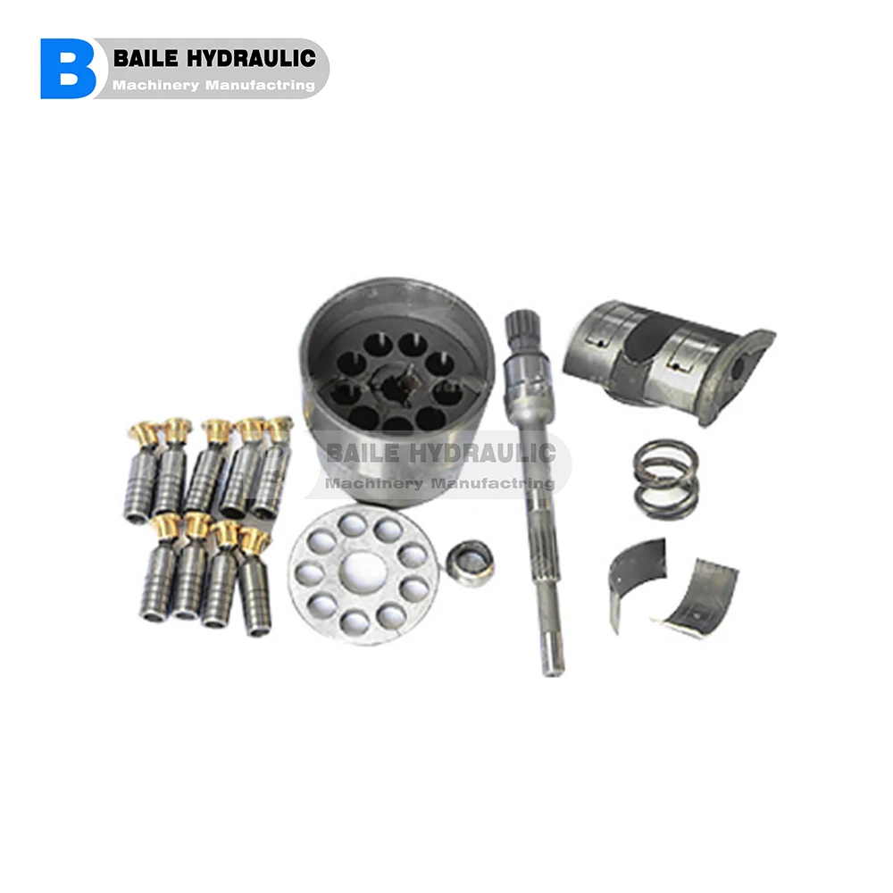
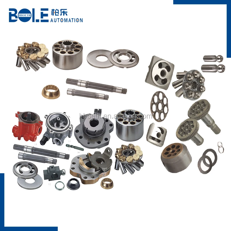
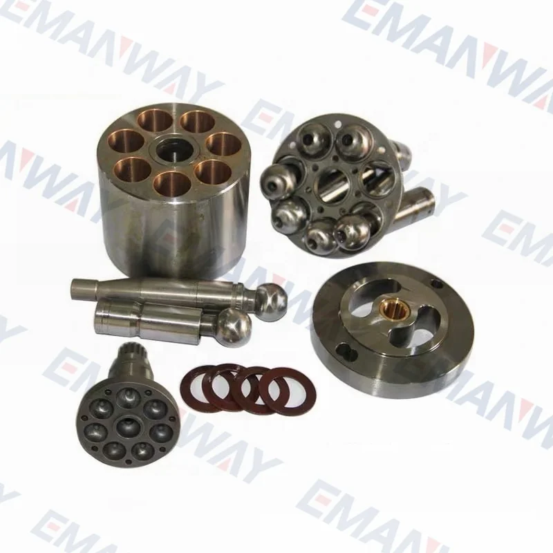
oilgear hydraulic pump parts free sample
At Oilgear, we make historically good pumps, valves and engineering systems. But mostly, we make your problems go away. As your technology advisor and provider for mission-critical jobs, we take on the toughest challenges in the industrial, subsea and mobile industries. We’re your one-stop problem-solver; nonstop when it comes to looking at your issues with fresh eyes. Even helping you prepare for scenarios you haven’t imagined yet.
At Oilgear, our top priority is always the health and safety of our customers and team. Please read our message regarding the COVID-19 (Coronavirus) outbreak here.
Oilgear isn’t in the business of making throwaway products. Oilgear pumps have legendary longevity. When they eventually wear down, they are specifically designed to be refurbished or repaired.
Unlike most of our competitors, Oilgear offers full life cycle support for all of our products, whether it’s a five-year-old pump or a 50-year-old pump. Our bespoke repair process includes disassembly, inspection, quotation, refurbishment with our OEM parts and complete testing.

Whether we have your unit in stock or not, repair is always an option. In fact, it may be your BEST option for obsolete and hard to find hydraulic pumps and motors. Letting us repair your unit can also be drastically cheaper than replacing it, especially if parts are hard to come by.
We not only will try our greatest to offer superb companies to just about every buyer, but also are ready to receive any suggestion offered by our shoppers for Mini Hydraulic Power Packs, Directional Valves, Manual Directional Control Valve, Base within the small business concept of Top quality initially, we want to fulfill more and additional friends within the word and we hope provide the ideal solution and services to you.
We are also focusing on enhancing the things administration and QC program in order that we could keep fantastic advantage within the fiercely-competitive enterprise for Massive Selection for Oilgear Hydraulic Pump Parts - Proportional Valves-GBV200 – Guorui, The product will supply to all over the world, such as: Jeddah, Gambia, Boston, Our products are exported worldwide. Our customers are always satisfied with our reliable quality, customer-oriented services and competitive prices. Our mission is "to continue to earn your loyalty by dedicating our efforts to the constant improvement of our products and services in order to ensure the satisfaction of our end-users, customers, employees, suppliers and the worldwide communities in which we cooperate".

These oilgear hydraulic pump parts are manufactured and assembled using sturdy and robust materials. Accordingly, they’re highly durable and give you long lifespans. With their innovative designs and advanced technologies, these oilgear hydraulic pump parts improve the efficacy of hydraulic machines by fitting in perfectly and with minimal resistance. Their quality is exemplary and warrants you the best outputs. As a measure to maintain top-rated oilgear hydraulic pump parts, only certified sellers and credible distributors are enlisted on the site, after having fulfilled all regulatory requirements.
If you are supplying pump supplies, you can find the most favorable prices at Alibaba.com. Whether you will be working with piston type or diaphragm type systems, reciprocating or centrifugal, Alibaba.com has everything you need. You can also shop for different sizes oilgear hydraulic pump parts wholesale for your metering applications. If you operate a construction site, then you could need to find some concrete pump solutions that you can find at affordable rates at Alibaba.com. Visit the platform and browse through the collection of submersible and inline pump system, among other replaceable models.
Alibaba.com has been an excellent wholesale supplier of oilgear hydraulic pump parts for years. The supply consists of a vast number of brands to choose from, comes in different sizes, operations, and power sources. You can get a pump for residential and large commercial applications from the collection. Whether you want a water pump for your home, or run a repair and maintenance business, and need a supply of oil gear hyd pump, you can find the product you want from the vast collection at Alibaba.com.therther it is for refrigeration, air conditioning, transfer, or a simple car wash business, anything you want, Alibaba.com has it.
A gear pump is a type of positive displacement (PD) pump. It moves a fluid by repeatedly enclosing a fixed volume using interlocking cogs or gears, transferring it mechanically using a cyclic pumping action. It delivers a smooth pulse-free flow proportional to the rotational speed of its gears.
Gear pumps use the actions of rotating cogs or gears to transfer fluids. The rotating element develops a liquid seal with the pump casing and creates suction at the pump inlet. Fluid, drawn into the pump, is enclosed within the cavities of its rotating gears and transferred to the discharge. There are two basic designs of gear pump: external and internal(Figure 1).
An external gear pump consists of two identical, interlocking gears supported by separate shafts. Generally, one gear is driven by a motor and this drives the other gear (the idler). In some cases, both shafts may be driven by motors. The shafts are supported by bearings on each side of the casing.
As the gears come out of mesh on the inlet side of the pump, they create an expanded volume. Liquid flows into the cavities and is trapped by the gear teeth as the gears continue to rotate against the pump casing.
No fluid is transferred back through the centre, between the gears, because they are interlocked. Close tolerances between the gears and the casing allow the pump to develop suction at the inlet and prevent fluid from leaking back from the discharge side (although leakage is more likely with low viscosity liquids).
An internal gear pump operates on the same principle but the two interlocking gears are of different sizes with one rotating inside the other. The larger gear (the rotor) is an internal gear i.e. it has the teeth projecting on the inside. Within this is a smaller external gear (the idler –only the rotor is driven) mounted off-centre. This is designed to interlock with the rotor such that the gear teeth engage at one point. A pinion and bushing attached to the pump casing holds the idler in position. A fixed crescent-shaped partition or spacer fills the void created by the off-centre mounting position of the idler and acts as a seal between the inlet and outlet ports.
As the gears come out of mesh on the inlet side of the pump, they create an expanded volume. Liquid flows into the cavities and is trapped by the gear teeth as the gears continue to rotate against the pump casing and partition.
Gear pumps are compact and simple with a limited number of moving parts. They are unable to match the pressure generated by reciprocating pumps or the flow rates of centrifugal pumps but offer higher pressures and throughputs than vane or lobe pumps. Gear pumps are particularly suited for pumping oils and other high viscosity fluids.
Of the two designs, external gear pumps are capable of sustaining higher pressures (up to 3000 psi) and flow rates because of the more rigid shaft support and closer tolerances. Internal gear pumps have better suction capabilities and are suited to high viscosity fluids, although they have a useful operating range from 1cP to over 1,000,000cP. Since output is directly proportional to rotational speed, gear pumps are commonly used for metering and blending operations. Gear pumps can be engineered to handle aggressive liquids. While they are commonly made from cast iron or stainless steel, new alloys and composites allow the pumps to handle corrosive liquids such as sulphuric acid, sodium hypochlorite, ferric chloride and sodium hydroxide.
External gear pumps can also be used in hydraulic power applications, typically in vehicles, lifting machinery and mobile plant equipment. Driving a gear pump in reverse, using oil pumped from elsewhere in a system (normally by a tandem pump in the engine), creates a hydraulic motor. This is particularly useful to provide power in areas where electrical equipment is bulky, costly or inconvenient. Tractors, for example, rely on engine-driven external gear pumps to power their services.
Gear pumps are self-priming and can dry-lift although their priming characteristics improve if the gears are wetted. The gears need to be lubricated by the pumped fluid and should not be run dry for prolonged periods. Some gear pump designs can be run in either direction so the same pump can be used to load and unload a vessel, for example.
The close tolerances between the gears and casing mean that these types of pump are susceptible to wear particularly when used with abrasive fluids or feeds containing entrained solids. However, some designs of gear pumps, particularly internal variants, allow the handling of solids. External gear pumps have four bearings in the pumped medium, and tight tolerances, so are less suited to handling abrasive fluids. Internal gear pumps are more robust having only one bearing (sometimes two) running in the fluid. A gear pump should always have a strainer installed on the suction side to protect it from large, potentially damaging, solids.
Generally, if the pump is expected to handle abrasive solids it is advisable to select a pump with a higher capacity so it can be operated at lower speeds to reduce wear. However, it should be borne in mind that the volumetric efficiency of a gear pump is reduced at lower speeds and flow rates. A gear pump should not be operated too far from its recommended speed.
For high temperature applications, it is important to ensure that the operating temperature range is compatible with the pump specification. Thermal expansion of the casing and gears reduces clearances within a pump and this can also lead to increased wear, and in extreme cases, pump failure.
Despite the best precautions, gear pumps generally succumb to wear of the gears, casing and bearings over time. As clearances increase, there is a gradual reduction in efficiency and increase in flow slip: leakage of the pumped fluid from the discharge back to the suction side. Flow slip is proportional to the cube of the clearance between the cog teeth and casing so, in practice, wear has a small effect until a critical point is reached, from which performance degrades rapidly.
Gear pumps continue to pump against a back pressure and, if subjected to a downstream blockage will continue to pressurise the system until the pump, pipework or other equipment fails. Although most gear pumps are equipped with relief valves for this reason, it is always advisable to fit relief valves elsewhere in the system to protect downstream equipment.
Internal gear pumps, operating at low speed, are generally preferred for shear-sensitive liquids such as foodstuffs, paint and soaps. The higher speeds and lower clearances of external gear designs make them unsuitable for these applications. Internal gear pumps are also preferred when hygiene is important because of their mechanical simplicity and the fact that they are easy to strip down, clean and reassemble.
Gear pumps are commonly used for pumping high viscosity fluids such as oil, paints, resins or foodstuffs. They are preferred in any application where accurate dosing or high pressure output is required. The output of a gear pump is not greatly affected by pressure so they also tend to be preferred in any situation where the supply is irregular.
A gear pump moves a fluid by repeatedly enclosing a fixed volume within interlocking cogs or gears, transferring it mechanically to deliver a smooth pulse-free flow proportional to the rotational speed of its gears. There are two basic types: external and internal. An external gear pump consists of two identical, interlocking gears supported by separate shafts. An internal gear pump has two interlocking gears of different sizes with one rotating inside the other.
Gear pumps are commonly used for pumping high viscosity fluids such as oil, paints, resins or foodstuffs. They are also preferred in applications where accurate dosing or high pressure output is required. External gear pumps are capable of sustaining higher pressures (up to 7500 psi) whereas internal gear pumps have better suction capabilities and are more suited to high viscosity and shear-sensitive fluids.
The invention pertains to a radial piston hydrostatic machine operable as a pump or as a motor and having a tapered pintle for valving motive fluid to the cylinders of a cylinder barrel journalled on the pintle. And more particularly it pertains to such a machine having a control to move the cylinder barrel on or off the taper of the pintle to adjust the running clearance between their mating tapered bearing surfaces in accordance with operating pressure and the flow of leakage fluid escaping at each end of the pintle.
This type of tapered pintle hydraulic pump or motor is shown and described in U.S. Pat. No. 2,231,361 issued Feb. 11, 1941. It shows an end cylinder arranged on the end of the cylinder barrel, a piston fitted in the end cylinder and secured to the driveshaft for coupling the cylinder barrel and drive shaft for rotation with each other. Leakage fluid escaping from between the tapered bearing surfaces of the cylinder barrel and pintle at thpe small end of the pintle enters the end cylinder and is discharged therefrom through a flow restricting passage. The pressure of the leakage fluid in the end cylinder urges the cylinder barrel toward the large end of the pintle. The machine is also provided with built in stops to limit the movement of the cylinder barrel in either direction and a prressure relief valve connected to a discharge passage for the leakage fluid to limit the pressure of leakage fluid in the end cylinder to a preset maximum value.
Although the tapered surfaces are machined to provide mating surfaces, machining tolerances leave some error which may be compensated in part by select fitting of pintle and cylinder barrel parts in order to provide at least as much leakage flow under normal operating condtions at the large end of the pintle as at the small end of the pintle. However this does not give positive protection against operating conditions that may cause the leakage flow along the bearing surfaces at the large end of the pintle to decrease below a minimum value necessary to lubricate and cool such bearing surfaces and prevent seizure therebetween.
The invention provides a radial piston hydraulic pump or motor having a cylinder journalled on a tapered pintle and axially adjustably positioned on the pintle to vary the running clearance between their bearing surfaces to maintain a prescribed minimum flow of leakage fluid therebetween and escaping at each end of the bearing surfaces sufficient to cool and lubricate the bearing surfaces.
A pump, for example, embodying the present invention and having an output capacity equivalent to 500 horsepower, is designed at rated output to provide a flow of leakage fluid between the bearing surfaces of the pintle and cylinder barrel on the order of 2 percent of pump output. The pump is also designed to have a maximum running clearance of 0.007 inch, as at start-up, and a minimum running clearance of 0.001 inch, as at maximum pressure and temperature.
Another object of the invention is to make cylinder barrel and pintle parts for pumps interchangeable without the necessity for select fitting by providing a control that maintains an effective minimum running clearance between both end portions of said parts to compensate for machining tolerances for all operating conditions of the pumps.
A variable displacement hydraulic machine, FIG. 1, is operable as a pump or as a motor, and for convenience is herein referred to as a pump. The pump comprises a closed casing 1, having a removable head 2 attached to its front end and a hub 3 formed integral with the casing at its rear end. A slideblock 4 is supported in a known manner for transverse horizontal movement in the casing. A hollow thrust member 6 is rotatably supported in the slideblock by thrust bearings 7, 8. The eccentricity of the axis of the thrust member 6 with respect to the axis of the cylinder barrel 20 is determined by the position of the slideblock 4. Such eccentricity determines the displacement of the pump.
Leakage fluid is conducted from end cylinder 32 through a small passages 37, 38, the latter extends axially through the pintle from one end to the other end thereof and in turn is connected to a passage 43 in a schematically illustrated valve block 39 mounted on the rear end of the pintle and the hub 3 of the casing. The associated passage 43 in the valve block is in turn connected, as hereinafter described, to a passage 48 through the casing 1 so thaat the fluid escaping therethrough may return through a drain passage from the casing to reservoir, not shown. The flow of liquid through the passage 43 in the valve block is limited by a suitable choke, such as an orifice 44, inserted in that passage downstream of valve 50, so that pressure which may be created in the end cylinderr 32 is sufficient to move the cylinder barrel to a position on the pintle. Thee escape of liquid from the end cylinder is resisted by the choke 44, and therefore results in an increase of pressure in the end cylinder. The pressure of liquid in the end cylinder continues to rise until it is high enough to overcome the resistance of the bias forces provided by hydraulic pressure acting between the pintle and cylinder, and by the force of the springs 36, then the pressure in the end cylinder 32 will move the cylinder barrel toward the large end of the pintle to reduce the running clearance between the cylinder barrel and the pintle, and reduce the flow of leakage through it to the end cylinder at a point where the pressure in the end cylinder can be maintained by the rate of flow through the orifice 44.
The valve block 39 contains a servovalve 50, comprising a valve chambper 51 one end of which is connected to the passage 43 receiving fluid escaping from the end cylinder at the small end of the pintle and the other end is connected to the passage 45 receiving fuid escaping through the collection groove 40 at the large end of the pintle bearing surface. A drain opening 53 serving as an additional drain opening from said chamber is located intermediate said end passages and is normally blocked by a movable valve member 52 in said valve chamber. The valve member 52 may be moved entirely by hydraulic forces or also may be biased by a light spring 54 in a direction to normally block the drain opening 53 and to prevent hunting of the valve. One end of the servovalve is onnected to the passages 43, 38, conducing leakage fluid from the end cylinder 32 at the small end of the pintle an the other end of the servovalve is connected to the passages 45, 42 conducting leakage fluid from the collection groove 40 at the large end of the pintle. The servovalve 50 is connected ahead or upstream of the orifices 44, 46 so that the pressure developed at the orifices appears in the servovalve to react on opposite ends of the valve member.


 8613371530291