
mud agitator manual manufacturer
Derrick mud agitators include an explosion-proof, “C” faced motor, reduction gearbox (helical-bevel gears for horizontal agitators or all helical gears for vertical units), impeller, and shaft with assembly bushings. Motors range from 5 to 30 HP and may be supplied in several power configurations.
Attaching the motor directly to the gearbox protects correct alignment that can increase bearing life and provides 95 percent efficiency in power transfer to the impeller. Using this superior design surpasses standard worm drive gear assemblies by 30 percent, allowing Derrick agitators to do the same work at far less horsepower. By unitizing the motor and gearbox, weight and space requirements are reduced. Horsepower, mechanical configuration, impeller diameter, and shaft length are customized to tank dimensions and maximum mud weights. Available horsepower ratings* are: 5, 7.5, 10, 15, 20, 25, and 30.
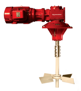
The MAX2000® Agitator features a rugged cast iron gearbox that houses helical bevel gearing. The gear sets are precisely ground to prevent all but the slightest amount of backlash in the gear sets. This feature promotes longer life by eliminating the high impact forces generated when the unit is energized at start-up. Each helical bevel gear stage is 98% efficient. A typical worm gear set is only 85% efficient, since it loses most of its efficiency through the generation of heat.
Internal gears and bearings are lubricated with mineral oil. When the ambient temperature drops below 23ºF or rises above 140ºF, a synthetic lubricant should be substituted. A unique feature of the MAX2000® Agitator is the lower bearing, which can be maintained from the top of the tank. This feature eliminates the need for in-tank inspections of the lower bearing, and also provides a barrier of grease that can be expunged out the lower seal. The lower seals are arranged to accommodate the grease pocket and make for a four-tier layer of protection for the gearing. The end result means the lower bearing stays in contact with good, uncontaminated lubricant at all times. All four of these levels must be breached prior to loss of oil in the gearbox.
1. OverviewThis manual provides installation, operation, and maintenance instructions for AIPUmud agitators. The manual is divided into several parts to assist the user inreadilyaccessing the information.
Personnel responsible for transporting, installing, commissioning, operating, or performingmaintenance on this equipment are required to read and understand the instructionsprovided in this manual. One copy of this manual should be available and accessible at theequipment location.
2. Safety instructionsAll persons responsible for operation and maintenance of this equipment must read andunderstand all safety information in this manual prior to operating and/or maintaining theequipment. The safety warnings listed below are included in applicable proceduresthroughout this manual.
a. While operating agitator without/with load, add qualified lubricating oil to required oillevel into worm gearbox.b. To ensure proper balance and orientation when unit is raised and prevent damage tocomponents, attach lifting sling only between motor and gear drive. Do not attempt Liftingby attachment to eyebolt on motor or any other Location.c. Be sure that handling devices have sufficient lifting capacity to safely handle the weightof the equipment.d. Clarify the correct direction of agitator before usage.e. To avoid serious personal injury of un-expected motor startup, be sure equipment islocked out, tagged out, and de-energized prior to install / or maintenance and/or
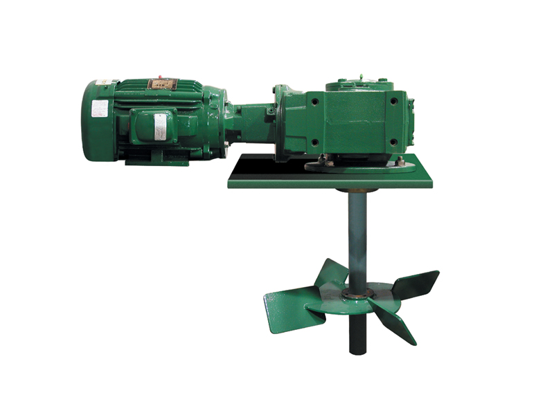
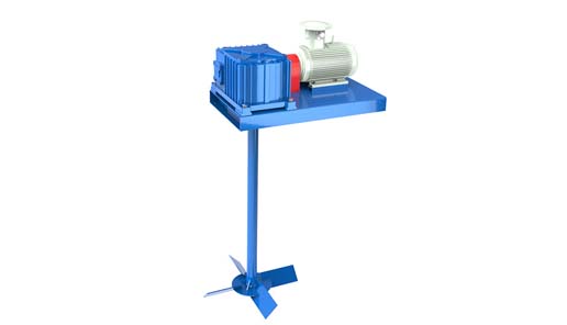
ApplicationAPMA series mud agitator is one of the important equipment for mud system. It ismainly used for agitating drilling fluids, avoid particle in fluids deposit to tank bottom.It is high-efficiency mud-mixing units offered in a wide array of custom sizes andconfigurations to accommodate virtually any mud tank. The horizontal drive is designedfor installations having limited space above the mud tank.
The mud agitator stirs mud slurry to maintain suspension of solids. The agitator is mountedon top of the mud tank and has one or two impeller(s) immersed in the mud slurry. Theimpeller shaft is directly coupled to an electric drive motor that is available in severalhorsepower ratings from 7.5 to 25.
AIPU does not authorize any other use of this equipment, intended usage of theequipment includes compliance with the operating, maintenance, and safety instructionsprovided in this manual。
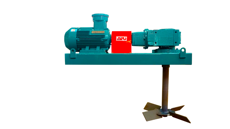
Mud agitator design should be based on tank dimension, inner depth and mudcondition. AIPU horizontal agitators utilize worm gear reducer. Welding type or castingtype impeller for option.The impeller is fixed to the shaft with bolts to avoid rotating or sway (connection with keygroove optional). Its vertical location on the shaft is determined as a height from the tankbottom corresponding to the impeller diameter times 0.75. For example, a 20” impellershould be mounted 15” above the bottom. AIPU recommends straight impeller bladesfor
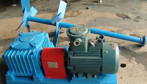
Features a. Utilize worm gear reducer. Compact design, perfect joggle and reliable operation. b. Worm gear reducer combined with explosion-proof motor, which enable stable performance in wild severe environment. c. Input shaft of explosion-proof motor are connected to gearbox with elastic coupling directly, rather than belt-drive. It enables stable speed of impeller. d. The mud agitators are high-efficiency mud-mixing units offered in a wide array of custom sizes, and configurations to accommodate virtually any mud tank. It is to avoid over-load of current during start up motor. e. Horizontal type of motor. It is convenient for installation, adjustment or replacement. Main parameters of agitator
Casting type 600mm 700mm Up:600mm Up:700mmimpeller, Down:600mm Down:600mm(Standard) 25:1 25:1 25:1 25:1RationOverall 900*700*600m 900*750*610mm 1100*840*705m 1200*1000*760mdimension m m m(L*W*H) 380V/50HZ Or 460V/60HZ, or customizedElectric SpecsShaft length and Customized shaft according to tank inner depth / mud condition optionalimpeller Explosion-proof motorRemarks Shaft stabilizer available Customized impeller diameter available
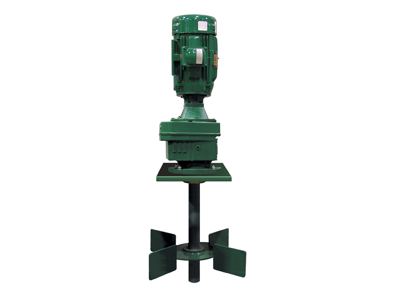
Major components AIPU mud agitator is made of explosion-proof motor, worm gear reducer. impeller, mounting plate, elastic coupling, and rigid coupling. Explosion-proof motor and worm gear reducer installed on mounting plate. Elastic coupling connect explosion-proof motor input shaft and gearbox input shaft. Impeller shaft and gearbox output shaft are connected by rigid coupling. Although the arrangement mud agitator components is identical across the various sizes and configurations, the drive motor, impeller, shaft length and diameter, gear drive, and motor orientation vary between models. Figure 2 shows the typical components of a mud agitator. The configuration for the same power rating is identical, except for the type of ear drive. The unit is shipped unassembled and requires assembly by a trained, qualified technician.
25 horsepower with customized hz and voltage; the power requirements are specified onthe customer order. Electric power, switching, and safety devices are provided by thecustomer.AIPU can offer starter for agitator as request. All components come from Siemensof Schneider.
ImpellerImpellers are available in diameters ranging from 20” to 52” to meet the needs of varioussize mud tanks. The impeller diameter is generally determined by the size of the tank.Larger or deeper tanks employ dual impeller units having a secondary impeller mountedcloser to the mud surface. The impeller is mounted on the shaft using a tapered lockingbushing. A bolt / key inserted in the impeller shaft locks the impeller to the shaft andprevents rotation. Canted impeller blades are desirable near the bottom of tanks more than5’ deep or where other forces of flow factor may be absent in the tank.
5. Model selection and installationBefore installation / disassembly, read and understand ALL safety information presented inthis manual and associated documents. Review the equipment handling procedures in themanual. Pay particular attention to information concerning “lift points” and the use ofspreader bars before lifting or moving the equipment.Failure to observe proper equipment handling procedures may result in serious personalinjury and/or damage to the equipment.
SizingFor proper mixing and suspension of solids, the mud agitator must be properly sized andinstalled. To properly size a mud agitator, proceed as follows:1. Select desired style – horizontal with welded / casting impeller2. Determine available electric power - 440V/460V/380,60HZ , 380V/400V/415V,50HZor customized.3. Select horsepower and impeller(s) as determined by the following factors:a. Tank design - round or squareb. Tank dimensionsc. Maximum mud weightd. Desired turnover ratio (TOR)
After gathering the required information, the agitator can be properly sized to meet thehorsepower demand and correct agitation for the application. To ensure accuratesizing, AIPU recommends clients to communicate with AIPU people to make sure sizeand model.Following are operational recommendations for mud agitators:1. Maintain uniform tank dimensions, i.e. equal width-to-length ratio or as close aspossible to equal.2. Avoid TOR values greater than 85 seconds, as this may jeopardize solids suspension.3. Avoid TOR values less than 40 seconds, as this may result in formation of a vortex andincrease air entrapment.
InstallationFollowing are the sequential steps of the mud agitator installation procedure. The sequencepresented is a guideline and may vary depending on the user’s facilities, previousexperience with this equipment, and optional equipment.1. Read and understand all safety information & handling procedures in this manual, andidentify the mud agitator components.2. Locate and weld mounting plate and stabilizer (if required) to tank structure.3. Place shaft in tank, and assemble impeller(s), tapered bushings, and male coupling onshaft.4. Install female coupling on gearbox shaft.5. Install motor and gearbox assembly, and attach shaft coupling to gearbox coupling.6. Connect electric power supply to drive motor.
LevelingTo prevent undue premature wear on the gearbox or coupling and ensure long-termreliability and efficiency of the mud agitator, the impeller shaft should rotate in a truevertical orientation. This vertical installation is achieved by ensuring that the mountingplate is absolutely horizontal. If a stabilizer is used, it must be directly aligned with the
center of the mounting plate. The following paragraphs describe the correct methods forinstalling the mounting plate and stabilizer.Agitator mounting dimension as showed as following.
Impeller assemblyInstall impeller with shaft, fixed with M14x140 bolt (2 bolts for each set of impeller) Theimpeller mounting location is kept by AIPU before delivery.For a canted single impeller or a dual impeller shaft, AIPU sets the distance of the lowerimpeller from the tank floor at 75 percent of the impeller diameter. Mount the optionalsecond impeller at a distance above the tank floor that is equal to 2/3 of the tank’smaximum mud height. For example, if the tank mud depth is 10’, the second (upper)impeller key should be centered approximately 6.5’ above the bottom of the tank. For tankdepths of 6’ or less, install a single straight impeller not more than 12” above the tankfloor.
7. Storage & handlingIf the machine will not be installed immediately, it should be covered with a tarpaulin(tarp). If unit is stored outdoors, use a UV- resistant tarp, or UV-resistant shrink-wrap.Install vents when using shrink-wrap. Seal operating and maintenance manual in plastic,and attach to unit.AIPU mud agitators are shipped disassembled except for motor and gearbox, which aresupplied as an assembly. All components including shaft are packaged in a sea/air worthywooden case.The delivered equipment should be transported on the ground using a forklift, lifting lugsas showed as fig.8.
This section contains initial and normal startup and shutdown procedures for the mudagitator. These procedures are designed to ensure safe operation and shutdown of theequipment.
Normal startup and operationAfter the initial startup, the mud agitator is started up and operated as follows:1) Verify that all personnel, tools, documents, and other material are clear of equipment.2) Turn on the mud agitator, and then open the associated mud feed and outlet systems.3) Observe the operation of the impeller shaft assembly as the tank fills with mud andverify continuous rotation of impeller(s).
Normal shutdown procedureTo shut down the mud agitator for any reason, first shut off the mud feed and then turn offelectric power to the agitator motor.
GeneralRoutine maintenance is critical to ensure maximum life and trouble-free operation of themud agitator. While the recommended maintenance schedule in this section is flexible,modifications should be based on experience with operating the equipment at yourfacilities. A maintenance log should be kept to help establish a routine maintenanceschedule, as well as to monitor and adjust the schedule as necessary throughout theequipment’s life. When determining a suitable maintenance schedule, consider duty cycle,ambient temperature, and operating environment.
10. TroubleshootingIf mud disturbance in the tank becomes unsatisfactory, check the possibilities listed belowand correct as described.PROBLEM POSSIBLE CAUSE REMEDYOver-temperature Motor and gearbox not installed Adjust to suitable position, suitably enable motor and gearbox axes concentric Abnormal abrasion of oil seal Trickle lubricating oil at oil seal ledge Lubricating oil too much or less Adjust oil quantity baseds on oil level plug Lubricating oil not pure, or not Replacing with new oil workable wellToo much Motor and gear box not fixed well Check and find out the loosingvibration and point, fasten correctlynoise worm gear supplementary tooth badly Replacing worm gear worn/ damaged supplementary tooth (connect AIPU) bearing badly worn or disabled Replacing bearing Linking bolts for coupling and agitator Fasten or replacing bolts output plate pull off, or foundation bolts pull off Impeller shaft bended or deformed Align the shaft Impeller local distortion or broken off Repair or replace impellerWorking current worm / gear in gearbox badly worn Inspection gearbox gradually,fluctuated greatly repair or replace relative parts Far-forth top circle of shaft rubbed with Align shaft or re-install stabilizer inner wall stabilizer
resold without alteration, which are covered by warranty from the original manufacturer. e. Failures due to abuse, misuse, or lack of proper recommended maintenance. f. Failures of equipment, which has in any way been repaired or altered except asauthorized by AIPU or equipment using components manufactured or repaired by anyother party than AIPU unless expressly authorized by AIPU. The foregoing warranty shall be herein referred to as the “Agitator Warranty”. TheMud Agitator Warranty is for the exclusive benefit of Purchaser. THE AGITATOR WARRANTY CONSTITUTES AIPU’S SOLE ANDEXCLUSIVE WARRANTY WITH RESPECT TO ANY AGITATOR PURCHASEDHEREUNDER, EXCEPT FOR THE AGITATOR WARRANTY, AIPU HEREBYDISCLAIMS ALL EXPRESS WARRANTIES (WHETHER ORAL, WRITTEN ORARISING BY PROMISE, DESCRIPTION OR SAMPLE) AND ALL IMPLIEDWARRANTIES, INCLUDING, WITHOUT LIMITATION, WARRANTIES OFNON-INFRINGEMENT, ANY WARRANTY OF MERCHANTABILITY ANDFITNESS FOR ANY PARTICULAR PURPOSE, AND ALL WARRANTIES
Purchaser represents that it has evaluated the AIPU Agitators in light of theAgitator Warranty and has determined that the AIPU Agitator are fit and sufficient forPurchaser’s operations (including the Processing applications). Purchaser acknowledgesthat it is solely responsible for evaluating and choosing the sites where the AIPUAgitator will be installed and the manner in which AIPU Agitators will be used. AIPU does not warrant that the Environmental Protection Agency (“EPA”) or anyother regulatory authority has approved or certified the AIPU Agitators for any purpose. Purchaser assumes any risk, burden and/or costs of EPA or their regulatorycompliance with respect to any AIPU Agitator acquired pursuant to this Agreement. AIPU has made no inspection of the sites where Purchaser intends to installthe Centrifuges and disclaims any warranties with respect to installation of the AIPUAgitators. Purchaser shall use its best efforts to ensure that all persons or entities rentingor leasing AIPU Agitators are informed of the foregoing exclusive warranty and warrantydisclaimer.
Our agitators feature the new dracomet coated corrosion resistant keyless coupling for easy installation and impeller adjustment. The units come complete with base plate, motor, gearbox, impeller, shaft & couplings.
Drilling mud is composed of extremely small particles and has a thick consistency. Its settling velocity is therefore low, and sediment should not be a problem if the contents in a tank can be kept in motion. But, due to the combination of the irregular shape of tanks and the inefficiency of conventional mixing systems, sediment build-up is a timeconsuming and expensive problem.
5W 7.5W 15W motor / gear-box Drilling Mud Mixing Industrial mud tank mud Agitators 5W 7.5W 15W motor / gear-box Drilling Mud Mixing Industrial mud tank mud Agitators 5W 7.5W 15W motor / gear-box Drilling Mud Mixing Industrial mud tank mud Agitators 5W 7.5W 15W motor / gear-box Drilling Mud Mixing Industrial mud tank mud Agitators 5W 7.5W 15W motor / gear-box Drilling Mud Mixing Industrial mud tank mud Agitators 5W 7.5W 15W motor / gear-box Drilling Mud Mixing Industrial mud tank mud Agitators 5W 7.5W 15W motor / gear-box Drilling Mud Mixing Industrial mud tank mud Agitators 5W 7.5W 15W motor / gear-box Drilling Mud Mixing Industrial mud tank mud Agitators 5W 7.5W 15W motor / gear-box Drilling Mud Mixing Industrial mud tank mud Agitators 5W 7.5W 15W motor / gear-box Drilling Mud Mixing Industrial mud tank mud Agitators 5W 7.5W 15W motor / gear-box Drilling Mud Mixing Industrial mud tank mud Agitators 5W 7.5W 15W motor / gear-box Drilling Mud Mixing Industrial mud tank mud Agitators 5W 7.5W 15W motor / gear-box Drilling Mud Mixing Industrial mud tank mud Agitators 5W 7.5W 15W motor / gear-box Drilling Mud Mixing Industrial mud tank mud Agitators 5W 7.5W 15W motor / gear-box Drilling Mud Mixing Industrial mud tank mud Agitators 5W 7.5W 15W motor / gear-box Drilling Mud Mixing Industrial mud tank mud Agitators 5W 7.5W 15W motor / gear-box Drilling Mud Mixing Industrial mud tank mud Agitators
As an SPX FLOW brand, Lightnin serves the challenging waste and water treatment sector, as well as the processing of solvents, fertilizers, food/beverages, pharmaceuticals and biofuels. The mixers and agitators, that are custom designed and fabricated, are used for equalization, neutralization, flocculation, aeration, sludge mixing, flash mixing and general blending purposes. The Lightnin industrial mixer portfolio covers both portable and larger fixed-mount units. All Lightnin equipment is designed to provide prolonged trouble-free operation regardless of the specific application demands. Through the proprietary gearbox and impeller technologies developed in recent times, we can offer the market advanced mixing solutions that are far more compact and power-efficient than ever before. They also have significantly greater operational lifespans, thanks to anti-fouling mechanisms and other state-of-the-art features. Consequently, customers are able to raise their productivity levels and avoid costly downtime issues, while also keeping the energy consumption involved to an absolute minimum.


 8613371530291